Proceeding Forum in Research, Science, and Technology (FIRST) 2016
D
ESIGNING
A S
UN
T
RACKER ON
M
AXIMUM
E
NERGY
P
OINT
BY
F
UZZY
L
OGIC
Ahyar Supani
1), Indarto
2), Yulian Mirza
3) 1)Computer Engineering Department, Politeknik Negeri Sriwijaya, Palembang, Indonesia E-mail:[email protected]
2)
Computer Engineering Department, Politeknik Negeri Sriwijaya, Palembang, Indonesia E-mail: [email protected]
3)
Computer Engineering Department, Politeknik Negeri Sriwijaya, Palembang, Indonesia E-mail: [email protected]
Abstract. Solar energy is a renewable energy, clean and friendly environment and has been found very large in the world. The use of solar energy makes it possible to convert them into electrical energy efficiently enough. The amount of maximum solar energy can be determined by tracking the sun as a controller that follows the sun movement trajectory by a panel of photovoltaic (PV). Solar tracker followed PV panel must be really precise so that the system that captures sunlight can provide the right data to the controller as well. The aim of this controller system follows the sun at the point of maximum energy that is supported by fuzzy logic to drive the PV panel. Fuzzy logic created and implemented into a system is as an intelligent controller. This intelligent controller gets the data input of sunlight to be converted into digital signals consisting of four digits, the data digits are a digit position of the sun. Four digits are divided two parts namely the two east-west digits and two north-south digits. Then the data will be processed by the system as an intelligent controller to drive the PV panel and in addition the system is given the four-digit data input having a high logic or 1 as the value of the reference input by digit domain [1111]. This intelligent controller implements a closed loop control system that will stop the movement of PV panels when the intelligent controller output digit value will be equal to a four-digit reference input. In this condition, it is a solar maximum power point and PV panel is facing the sun or 90 ° angle..
Keywords:Sun Tracker; fuzzy Logic; Solar Maximum Power Point, Close Loop Controller
I. INTRODUCTION
Demand for energy is increasing, and turned towards the source of energy available from fossil minyal also increasing environmental pollution that encourages researchers to explore new technologies, especially the production of electricity from clean and renewable sources of energy such as solar, wind and others. Solar energy is the primary energy source of the longest. Solar energy is a renewable energy and clean and have found it very big in every part of the world. The use of solar energy is allowed to convert them into mechanical or electrical energy with considerable efficiency. Information on the quality and amount of solar energy available in specific locations is very important for the development of solar energy systems. In addition, the amount of electrical energy that is obtained is proportional to the intensity of the sunlight that falls on the photovoltaic panels (PV), therefore it is important to know the position of the sun so as to achieve maximum energy achieved solar photovoltaic panels (PV) facing the sunlight.
In the study[1], to get the maximum yield of solar energy, it must be determined where the maximum solar radiation emanates. In studies [2] have done to determine the energy
of the sun, the sun's angle to the PV panel and the temperature to calculate the maximum solar energy by comparing the PV panel system uses a two-axis solar tracker with fixed PV panel. And also according to [3] to generate the prediction accuracy and the ability of ANFIS (adaptive neuro fuzzy inference system) to estimate the solar energy based on meteorological data measured in the form of minimum and maximum monthly temperature and duration of the sun shining. Then the data is processed and developed with ANFIS to simulate the sun's energy with the software or program so that this model is an efficient technique to predict the maximum solar energy.
application of photovoltaic panels and solar tracker application areas and [7] demonstrate the benefits potential system design solar tracker system is simple to use stepper motors and light sensors. In the study [8], a single-axis sun-tracking with two sensors designed. Data acquisition, control and monitor mechanical movement photovoltaic module is implemented based on a programmable logic controlling unit. Researcher [9] present the design and construction of a system of two-axis solar tracking in order to keep track of photovoltaic solar panels in the direction of propagation of the light line of solar radiation. To produce maximum solar energy, solar power systems are generally equipped with functions that calculate the maximum power point tracker as in [10], [11] and [12].
All of the research that has been done [1], [3], [2] and [4] explains to obtain the maximum amount of solar energy, the efficiency of photovoltaic systems should be developed three methods. The first method is to increase the power generation efficiency of the solar cell, the second relating to the efficiency of the control algorithm for energy conversion and the third is to adopt a tracking system (track) to get the maximum solar energy.
In this study has been designed adopters of solar tracker systems to get the sunlight that falls on the maximum photovoltaic panel by adjusting the position of photovoltaic panels. The method has been used to control the panels to follow the sun's movement using fuzzy so that flux obtained by the maximum panel.
The objectives of the research are
1. applying the circuit of four-quadrant LDR sensor on the east,west, north and south sides for detecting a sun trajectcy.
2. Implimenting a microcontroller minimum system as a photovoltaic minimum circuit following a sun trajectcy 3. Designing a fuzzy- logic-algorithm commanding the
photovoltaic panel to follow the sun movement.
II. LITERATURESTUDIES A. State of Art
It has some methods and system for predicting an amount of solar namely determination of method and place selction that a sun arises long, and the data are simulated by ANFIS algorithm, a design and implement solar-tracking method, system and photovoltaic panel will be following a sun movement. The algorithm is designed and implemented on solar-tracking experiment platform using tri-positional control strategy (3-position).
In this research, a method has been designed to a sun-track to have a maximum sunrise energy by fuzzy logic controller. This method has advanced a sun track based on light sensor as a fuzzy input in control system. And then the maximum point of sun flux is an approach as photovoltage panel facing to a sun directly and results maximum solar power.
B. Before Related research
Research that has been conducted by [13] describes the composition and interconnect systems such as Fig. 1. For closed-loop approach to tracking, solar tracker problem is
how to cause the location (output) photovoltaic panels (PV) to follow the location of the sun (input) as close as possible. Feedback controller of basis LDR sensor consists of a sensor, amplifier and comparator. In the workings of the tracker, LDR sensor measures the intensity of the sun as a reference input signal. Voltage unbalance generated by the sensor LDR amplified and then generate the error voltage with the threshold voltage Special (tolerance). If the comparator output is high, then the motor driver and the relay is activated, causing the motor rotate tracker (azimuth and elevation) and set the PV facing the sun. Furthermore, the feedback controller displays vital functions: PV panel and sunrise is monitored constantly and sends control signals untk differential PV panel moves to the error voltage is less than the threshold voltage.
Fig. 1 A sun track design block diagram [13]
Research has been done by [4] to design and build a solar tracker algorithm (sun-tracking) explained in order to implement algotima tracker (tracking algorithm) should be placed on the structure that frees the movement or rotation panel on one or two axes. In addition, the structure with one or two degrees of freedom should be associated with the movement of the actuator to be effective. Equipment used in these experiments is a miniature didactic equipment that is equipped with a set of three photovoltaic cells placed on the same plane, in the assembly bar above. Framework installed solar cells including two motor-power from a DC supply voltage of 24 Volt and freeing position on the two axis of rotation. The free movement of solar panels on the mechanical structure is orizontal direction (azimuth angle) and the angle of slope (elevation angle). It appears that the variation of azimuth angle wider than a whole day, and the variation of elevation relative to the annual time. This is because the nature of trayeksi the sun throughout the day, depending on the season. In addition, to determine the maximum light intensity in the photovoltaic cell panel right on the bottom line, four photovoltaic cells can be mounted two in each direction, on the side adjacent and form a line 90o (perpendicular). The working principle of photovoltaic cells as follows: light intensity rises evoke strain value of the photosensitive cells. All terminals provide measurement and integration in the development of the control loop.
Proceeding Forum in Research, Science, and Technology (FIRST) 2016 in Iseyin, Nigeria. The process was developed with adaptive
neuro-fuzzy inference system (ANFIS) to simulate the sun's energy. ANFIS network has three neurons in an input layer of neurons in the output layer. Input is the maximum temperature of the monthly average (Tmax), minimum temperature average monthly (Tmin) and duration of the sun shining monthly average (n). System performance is determined through simulation results. ANFIS results compared with the results of experiments using the root-mean-square error (RMSE) and coefficient of determination (R2). The result is significant in improving forecast accuracy and ability ANFIS simulate the sun's energy. Statistical characteristics RMSE = 1.0854 and R2 = 0.8544 is generated in the training phase and RMSE = 1.7585 and R2 = 0.6567 in the testing phase. These results show an efficient technique to predict the global solar energy for the benefit of practice.
In the study [1] describes the selection of optimization based on fuzzy logic, a weighted linear combination (WLC) that menpunyai average risk and able to involve coating weight, and process priority through multiple criteria decision making (MCDM). In this way after the identification, assessment criteria layer by using fuzzy due to the uncertainties and determine its interests, combined layer. Overall, these results indicate that the combination of fuzzy logic, WLC and MCDM have high accuracy and positioning on the optimal placement of the sun and in this way the climate layer is very important.
C. Microcontroller
The microcontroller is a computer system that has one or more very specific task, as opposed to the Personal Computer that has a variety of functions. This microcontroller enabled to process input data sunlight and reference data and also perform position location for sunlight. Fig. 2 below is a configuration pin AT89S52 [14].
Fig. 2 AT89S52 pin configuration[14]
Microcontroller AT89S52 used type which has 8 Bit RISC architecture, so all the instruction code is packaged in 16-bit (16-bits word) and most of the instructions executed in one clock cycle. A highly significant difference compared to the MCS-51 instruction that requires up to 12 clock cycles. D. A Position Control
According [15] explains that the movement of the robot-like arm movement at the joints are movement-oriented
control of the position. That is, the definition of robot movement is based on the position shift. If the robot has reached the position in accordance with the reference motion actuator will "stop", in other words, if the actuator is the motor, the motor will stop rotating. Thus the position control on a DC motor can be illustrated in Fig. 3. Fig. 3 is an analogy of movement of the sun's position is changed. If the PV panel has reached a reference position in accordance with the actuator or DC motor will stop so that the PV panels are always facing straight sunlight.
Fig. 3. A position control diagram of a motor DC
E. Light Detector Resistance (LDR) and Comparator Photo resistor is also known as LDR with the Fig. 4 is a light-sensitive component that is often used to indicate the presence or absence of light or to measure the intensity of light. At the time of the dark resistance is very high,
sometimes reaching 1 M Ω , but when LDR disorotin light,
then the resistance down instantly, even a few ohms, depending on the intensity of the light. LDR has sensitivity that varies with the wavelength of light that is applied and a nonlinear component. LDR is used a lot of applications but are sometimes made absolute with other components such as photodiode and phototransistor. [16]
Fig. 4. Light dependent resistor[16]
The basic configuration for comparator negative voltage using op-amp is also known by inverting comparator circuit that detects when the input signal (Vin) is low or negative of the reference voltage (Vref.) Produce output (Vout) is high as in Fig. 5[17], accessed June 20, 2016
In this comparator obtained a number of conditions, namely
• Vin high voltage, then Vin> Vref, then Voutput low (- Vsupply)
• Low voltage Vin, then Vin <Vref., Then Voutput high (+ Vsupply)
F. Fuzzy Logic
Basic fuzzy logic developed by Lotfi A. Zadeh, a professor at the University of California Berkley. He serves not only the fuzzy logic control methods but also methods to set the process data as a substitute member subset is not set. Nonlinear mapping input data set to the data output scalar known as fuzzy logic system. Fuzzy logic system consists of four parts, namely fuzzification, rule, inference engine and defuzzification. Fig. 6 shows the general architecture of the system components and fuzzy logic [18].
Fig 6. Fuzzy logic architecture [18]
Threre are two fuzzy logic reasonings namely Mamdani and Sugeno, both are almost the same only difference output Sugeno system to not be constant but in the form of fuzzy sets or systems of linear equations. A model of fuzzy variables are often described in terms of its fuzzy space composed of multiple fuzzy sets, fuzzy sets which overlap which each fuzzy set describing a certain sense of the variables that are allowed in the problem. Overall, problem space of the smallest value to the largest value is allowed called the universe ofdiscourse [19].
Universe of discourse on the model of the angle variable is 45oto 135owith 6 domain of fuzzy sets: the angle1 is 0-60o, angle2 : 45o-75o, angle3:60o-90o, angle4:75o-105o, angle5:900-120o, angle6:105o-135o, angle7:120o-180o. Fig. 7 shows the concept of the suntrack angle model parameters .
Fig. 7 Universe of discourse sunrise angle
A triangle curve is basically a combination of a linear line in Fig. 8.
Fig. 8 A triangle curve
Membership function µ[x] uses an equation (1) referring to Fig.3.
(1)
III. RESEACHMETHODOLOGY A. A Block Diagram
In the application of solar tracker systems follow a block diagram of hardware design in Fig. 9.
Fig. 9. A sun-tracker hardware block diagram design Input is the sunlight that falls on the sensor LDR, and also the maximum power point of the sun that falls on a PV panel. The process is a fuzzy logic algorithm processing to the universe of the speaker is the angle of elevation. The output is a DC motor that drives the movement of PV panels follow a predetermined angle 45o, 60o, 90o, 120o, 135o.
B. A Design ofFuzzy Sun-TrackingAlgorithm
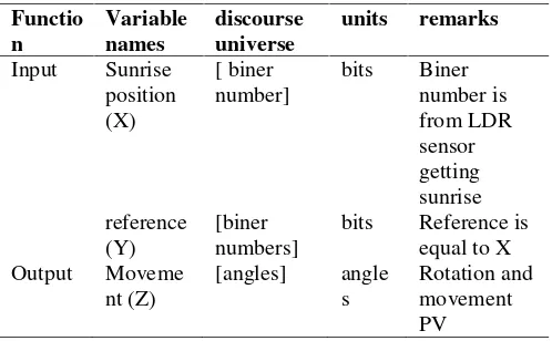
This tool is made has two inputs that sunlight is converted into four-bit digital (X) and input as a reference (Y) that serves marks the point of stopping rotation of DC motors and motion PV panel. This variable is a fuzzy input is designed in Table 1.
TABLE I
FINPUT OUPUT VARIABLES
Functio n
Variable names
discourse universe
units remarks
Input Sunrise position (X)
[ biner number]
bits Biner number is from LDR sensor getting sunrise reference
(Y)
[biner numbers]
bits Reference is equal to X Output Moveme
nt (Z)
[angles] angle s
Proceeding Forum in Research, Science, and Technology (FIRST) 2016 Furthermore table 2 determine the fuzzy sets for each
variable used tables 1 and sensor arrangement East, West sensors, sensor North, South sensors in the form of domain [TBUS].
TABLE III FUZZYSETS
Variables Fuzzy set names Domains Units
Sunrise positions (X)
angle (1) (0-45o) [1010] bit angle(2)(45o–60o) [1010] bit angle (3) (60o–90o) [1111] bit angle (4) (90o –
120o)
[1111] bit
angle (5) (120o –
135o)
[0101] bit
angle (6) (135o –
180o)
[0101] bit
angle (7)
gelap/malam
[0000] bit
Reference (Y)
Aligning to sunrise (90o)
[1111] bit
PV panel position movement (Z)
motor x rotation motor y rotation
[0000 1111] [0000 1111]
bit
After a fuzzy set is created, it can be done determines the rules. Rules can be formed from the set simulated in Matlab. The rule is:
1. If X angle (0-45o) or [1010] then motor X moves to east and motor Y to north.
2. If X angle (45o–60o) or [1010] then motor X moves to east and motor Y to north.
3. If X angle (60o – 90o) or [1111] then motor X and motor Y does not move.
4. If X angle (90o – 120o) or [1111] then motor X and motor Y does not move
5. If X angle (120o–135o) or [0101] then motor X moves to west and motor Y to south.
6. If X angle (135o–180o) or [0101] then motor X moves to west and motor Y to south
7. If X anglei [0000] then motor X moves to east.
The position of the sun that illuminates the sensor does not occur simultaneously when east and west sensor has a logic 1 and north and south logic 0 with domain logic [1100] otherwise [0011]. The position of the logical domains that can happen in [1011], [1010], [1001], [0111], [0110], [0101].
C. A design of Photovoltage Panel Position Feedback Control
The design of feedback control based on the Fig. 10, where the fuzzy controller will regulate the movement of the DC motor and the PV panels and will stop if the digit is generated by the movement of a PV panel is the same as the digit reference [1111] when all four sensors LDR gets sunlight maximum (the maximum point).
Fig. 10. PV panel feedback control design D. A design of LDR Sensor Position Hardware
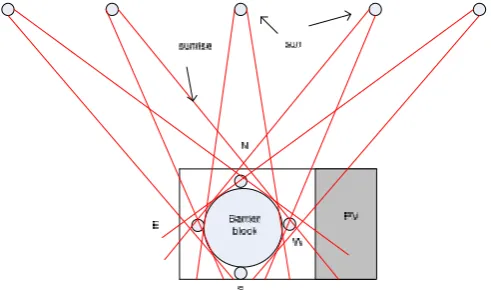
Fig. 11 is a draft position sensor LDR and PV panels are combined and placed on a motor bike X and Y so that the sensor LDR and PV panels will move in unison. Trayeksi light of the sun from east to west and illuminates the sensor LDR and PV panels. PV panels and sensors LDR will move in the direction of motion of the sun rotated by the motor X Y horizontal direction while the motor will rotate sensors and PV panels with the direction of motion north to south or vice versa because the Earth also rotates on its axis once around the sun. Beam barrier function of the LDR sensor blocking sunlight.
Fig. 11. PV panel and LDR sensor position design
IV. RESULTS ANDANALYSIS
Fig. 12. PV panel default position without sunrise
TABLE IIIII THE MEASUREMENT INCREASING PER15O
SUNRISE TOPV PANEL, 45O
-135O
No Angle between sunrise
and PV Panel
Angle Pvpanel move
1 Default position without sunrise
Tegak lurus or right angle to earth
2 45 26
3 60 60
4 75 75
5 90 90
6 105 105
7 120 120
8 135 154
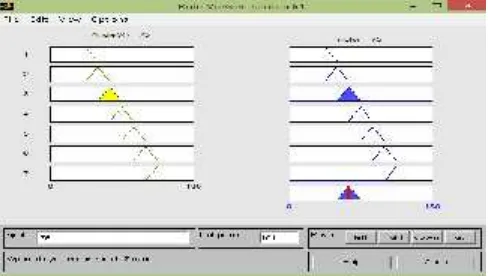
Next, the measurement of design result is simulated by Matlab Tool in Fig. 13 explaining the angle of sunrise to PV panel an amount of 75othat why motor DC also moves PV panel an amount of 75oto allign the sunrise to PV panel. So, at this position point the PV panel has maximum solar energy aligning to sunrise.
Fig. 13. The sunrise and PV panel angle move similar Table 4 is measurement by 60o-75oshowing the difference of between sunrise and PV panel angle to PV panel angle movement, where measurement difference is average 0.38 and -0.36. The diffirence amount is less than 1 showing between the sunrise and PV panel is allignment.
TABLE IVV THE MEASUREMENT BY60O
-75O
No Angle
between sunrise and PV Panel
Angle Pvpanel move
Measurement difference
1 Default position without sunrise
Tegak lurus or right angle to earth
2 60 60 0
3 61 61.3 0.3
4 62 62.6 0.6
5 63 63.6 0.6
6 64 64.6 0.6
7 65 65.6 0.6
8 66 66.3 0.3
9 67 67.1 0.1
10 68 67.9 -0.1
11 69 68.7 -0.2
12 70 69.5 -0.5
13 71 70.4 -0.6
14 72 71.4 -0.6
15 73 72.4 -0.6
16 74 73.7 -0.3
17 75 75 0
average 0.38 -0.36
Fig.14 is diffirence angle amount between sunrise and PV panel movement getted in Matlab Tool simulation.
Fig. 14. Difference angle amount sunrise to PV panel
V. CONCLUSIONS
Proceeding Forum in Research, Science, and Technology (FIRST) 2016 ACKNOWLEDGMENT
I would like to thank State Polytechnic of Sriwijaya for giving the fund grant in this research.
REFERENCES
[1] Zoghi Mahmood, Amir Houshang Ehsani, Mahdis Sadat, Mohammad javad Amiri, Sepideh Karimi, 2015, Optimization solar site selection by fuzzy logic model and weighted linear combination method in arid and semi-arid region: A case study Isfahan-IRAN, Renewable and Sustainable Energy.
[2] Yilmaz Aban, Hasan Riza Ozcalik, Osman Dogmus, Furkan Dincer, Oguzhan Akgol, Muharrem Karaaslan, 2015, Design of two axes sun tracking controller with analytically solar radiation calculations, Renewable and Sustainable Energy, Volume 43, Pages 997-1005. [3] Olatomiwa Lanre, Saad Mekhilef, Shahaboddin Shamshirband,
Dalibor Petkovic, 2015, Adaptive neuro-fuzzy approach for solar radiation prediction in Nigeria, Renewable and Sustainable Energy Reviews, Volume 51, Pages 1784-1791.
[4] Iulia Stamatescu, Ioana Fagarașan, Grigore Stamatescu, Nicoleta Arghira, Sergiu Stelian Iliescu, 2014, Design and Implementation of a Solar-Tracking Algorithm, Procedia engineering Journal, Volume 69, pages: 500-507.
[5] Hruska F, 2011, Experimental photovoltaic system, Annals of DAAAM for 2011 & Proceedings of the 22nd International DAAAM Symposium, Volume 22, No. 1, ISSN 1726-9679 ISBN 978-3-901509-83-4, Editor B. Katalinic, Published by DAAAM International, Vienna, Austria, EU.
[6] Hruška F., 2009, Experimental Photovoltaic System, Proceedings of the 20th International DAAAM Symposium “Intelligent Manufacturing&Automation” DAAAM 2009, 25-28.11.2009, Vienna, Austria, ISBN 978-3-901509-70-4, pp. 923-924, DAAAM International, Vienna.
[7] J. Rizk, Y. Chaiko, 2008, Solar Tracking System: More Efficient Use of Solar Panels, World Academy of Science, International Journal of Engineering and Technology, Vol. 41
[8] Ali Al-Mohamad, 2004, Efficiency improvements of photo-voltaic panels using a Sun-tracking system, International Journal of Applied Energy, Volume 79.
[9] M. R. I. Sarker, Md. Riaz Pervez, R.A Beg, 2010, Design, Fabrication and Experimental Study of a Novel Two-Axis Sun Tracker, International Journal of Mechanical & Mechatronics Engineering, IJMME-IJENS Vol: 10.
[10] J. Surya Kumari, Ch Sai Babu, 2011, Comparison of maximum power point tracking algorithms for photovoltaic system, International Journal of Advances in Engineering & Technology, 1 (5) (2011), pp. 133–148.
[11]Yu-Chi Wu , Meng-Jen Chen , Sih-Hao Huang , Ming-Tsung Tsai , Chia-Huang Li, 2013, Maximum power point tracking on stand-alone solar power system: Three-point-weighting method incorporating mid-point tracking, International Journal of Electrical Power & Energy Systems,Volume 52, November 2013, Pages 14–24.
[12] Anastasios I. Dounis, Panagiotis Kofinas, Constantine Alafodimos, Dimitrios Tseles, 2013, Adaptive fuzzy gain scheduling PID controller for maximum power point tracking of photovoltaic system, Renewable Energy International Jounal, Volume 60, December 2013, Pages 202–214
.
[13] Wang Jing-Min and Lu Chia-Liang, 2013, Design and Implementation of a Sun Tracker with a Dual-Axis Single Motor for an Optical Sensor-Based Photovoltaic System, International Journal of sensors, Volume 13, pages : 3157-3168.
[14] Supani Ahyar, 2015, Penerapan logika Fuzzy dan Pulse Wave Modulationuntuk Sistem Kendali Kecepatan RobotLine Follower, Jurnal INKOM LIPI Vol. 9, No. 1, hal. 1-10.
[15] Pitowarno E., 2006, Robotika : Desain, Kontrol, dan Kecerdasan Buatan, Andi Offset, Yogyakarta.
[16] ________,Photoresistor,http://www.resistorguide.com/photoresistor/ diakses tgl 20 Juni 2016
[17] _________, Comparator, http://www.electronics-tutorials.ws/opamp/op-amp-comparator.html diakses 20 Juni 2016
[18] P. Singhala, D. N. Shah, B. Patel, 2014,Temperature Control using Fuzzy Logic, International Journal of Instrumentation and Control Systems (IJICS), Vol. 4, No. 1, pp:1-10.
[19] Kusumadewi, 2002, “Analisis Desain Sistem Fuzzy menggunakan Tool Box Matlab”, 1stEd., Yogyakarta: Graha Ilmu , 2002, pp.: 25,
![Fig. 1 A sun track design block diagram [13]](https://thumb-ap.123doks.com/thumbv2/123dok/1433644.2028440/2.595.319.548.253.315/fig-sun-track-design-block-diagram.webp)
![Fig. 2 AT89S52 pin configuration [14]](https://thumb-ap.123doks.com/thumbv2/123dok/1433644.2028440/3.595.318.555.615.719/fig-at-s-pin-configuration.webp)