Stamatios V. Kartalopoulos
Next Generation Intelligent Optical
Networks
Dr. Stamatios V. Kartalopoulos The University of Oklahoma Room 4413
Schusterman Center
4502 E. 41st Street, Bldg 4, Room 4413 Tulsa, OK 74135
USA
ISBN: 978-0-387-71755-5 e-ISBN: 978-0-387-71756-2
Library of Congress Control Number: 2007933715 c
2008 Springer Science+Business Media, LLC
All rights reserved. This work may not be translated or copied in whole or in part without the written permission of the publisher (Springer Science+Business Media, LLC, 233 Spring Street, New York, NY 10013, USA), except for brief excerpts in connection with reviews or scholarly analysis. Use in connection with any form of information storage and retrieval, electronic adaptation, computer software, or by similar or dissimilar methodology now known or hereafter developed is forbidden.
The use in this publication of trade names, trademarks, service marks and similar terms, even if they are not identified as such, is not to be taken as an expression of opinion as to whether or not they are subject to proprietary rights.
Preface
Optical networks have been in commercial deployment since the early 1980s as a result of advances in optical, photonic, and material technologies. Although the initial deployment was based on silica fiber with a single wavelength modulated at low data rates, it was quickly demonstrated that fiber can deliver much more bandwidth than any other transmission medium, twisted pair wire, coaxial cable, or wireless. Since then, the optical network evolved to include more exciting technologies, gratings, optical filters, optical multiplexers, and optical amplifiers so that today a single fiber can transport an unprecedented aggregate data rate that exceeds Tbps, and this is not the upper limit yet. Thus, the fiber optic network has been the network of choice, and it is expected to remain so for many generations to come, for both synchronous and asynchronous payloads; voice, data, video, interactive video, games, music, text, and more.
In the last few years, we have also witnessed an increase in network attacks as a result of store and forward computer-based nodes. These attacks have many malicious objectives: harvest someone else’s data, impersonate another user, cause denial of service, destroy files, and more. As a result, a new field in communication is becoming important, communication networks and information secu-rity. In fact, the network architect and system designer is currently challenged to include enhanced features such as intruder detection, service restoration and countermeasures, intruder avoidance, and so on. In all, the next generation optical network is intelligent and able to detect and outsmart malicious intruders.
This is the first book, to the best of my knowledge, which bridges two disjoint topics, optical networks and network security. It provides a comprehensive treatment of the next generation optical network and a comprehensive treatment of cryptographic algorithms, the quantum optical network, including advanced topics such as teleportation, and how detection and countermeasure strategies may be used. Therefore, we believe that this book differentiates from many others and presents a holistic approach to the treatment of secure optical networks, including fiber to the home (FTTH) and free space optical (FSO).
This book deserves my thanks and appreciation because it came into being after the persistence of Mr. Jason Ward, the expert “literal” eyes of Mrs. Caitlin Womersley, and the many management and production personnel of Springer US anonymous to me.
I hope that the next generation optical network will be intelligent, and when using wireless tech-nologies at the edge, it will enable unlimited and secure communication multi-services with a single and portable device to anyone, anyplace, anytime at low cost.
Stamatios V. Kartalopoulos, Ph.D.
Acknowledgements
To my wife Anita, son Bill, and daughter Stephanie for consistent patience and encouragement. To my publishers and staff for cooperation, enthusiasm, and project management. To the anonymous reviewers for useful comments and constructive criticism. And to all those who worked diligently on the production of this book.
Contents
1 Communication Networks. . . 1
1.1 Analog and Digital Transmission . . . 1
1.2 Breaking the Traffic Barrier . . . 3
1.3 Voice and Data Networks . . . 5
1.3.1 PSTN and the SS7 protocol . . . 5
1.3.2 Data Networks and Protocols . . . 8
1.3.3 Narrowband, Broadband, and Ultraband Services . . . 9
1.3.4 Circuit Switched Versus Store and Forward . . . 10
1.3.5 Traffic and Service Evolution in Optical Networks . . . 12
1.3.6 Reliability of Optical Networks . . . 12
1.3.7 Security in Optical Networks . . . 12
References . . . 13
2 Digital Networks. . . 15
2.1 Synchronous Optical Networks: SONET/SDH . . . 15
2.1.1 Introduction . . . 15
2.1.2 SONET Frames . . . 17
2.1.3 Virtual Tributaries and Tributary Units . . . 19
2.1.4 STS-N Frames . . . 22
2.1.5 Maintenance . . . 23
2.2 Asynchronous Data/Packet Networks . . . 24
2.2.1 Introduction . . . 24
2.2.2 Synchronization and Timing . . . 25
2.2.3 Data Traffic . . . 25
2.2.4 Packet Networks . . . 26
2.3 Review of Data Networks . . . 28
2.3.1 Asynchronous Transfer Mode . . . 28
2.3.2 Ethernet . . . 32
2.3.3 Gigabit Ethernet . . . 33
2.3.4 10 Gigabit Ethernet . . . 36
2.3.5 FDDI . . . 37
2.3.6 Switched Multi-megabit Data Services . . . 39
2.3.7 Frame Relay . . . 39
2.3.8 The Transmission Control Protocol . . . 39
2.3.9 The User Datagram Protocol . . . 40
2.3.10 The Real-Time Transport Protocol . . . 41
2.3.11 Internet Protocol . . . 41
2.3.12 The Point-to-Point Protocol . . . 43
2.3.13 4B/5B and 8B/10B Block Coding . . . 46
2.3.14 Fiber Channel . . . 47
2.3.15 ESCON protocol . . . 50
2.3.16 FICON Protocol . . . 51
2.4 Resilient Packet Ring . . . 52
References . . . 53
3 WDM Technology and Networks. . . 55
3.1 Introduction . . . 55
3.2 The Optical Fiber in Communications . . . 55
3.2.1 Propagation of Light in Matter . . . 56
3.2.2 Effects That Affect the Propagation of Light in Fiber . . . 57
3.3 The Optical Communications Spectrum . . . 63
3.4 Types of Fiber . . . 65
3.4.1 Optical Power Limit . . . 66
3.4.2 Fiber Birefringence . . . 67
3.4.3 Fiber Dispersion . . . 67
3.4.4 Non-linear Phenomena Cause Positive and Negative Effects . . . 69
3.5 Optical Amplifiers . . . 69
3.5.1 Raman Amplification . . . 70
3.5.2 EDFA Amplification . . . 71
3.5.3 SOA Amplification . . . 73
3.6 Optical Add-Drop Multiplexers . . . 73
3.7 DWDM Networks . . . 73
3.7.1 DWDM Network Topologies . . . 74
3.7.2 Optical Network Interfaces . . . 75
3.7.3 Network Switching . . . 78
3.7.4 Timing and Synchronization . . . 81
3.7.5 Channel and Link Protection . . . 81
3.7.6 Routing . . . 82
3.8 Access WDM Systems . . . 83
3.8.1 The General PON . . . 84
3.8.2 CWDM-PON . . . 87
3.8.3 TDM-PON . . . 87
3.8.4 TDM-PON Versus WDM-PON . . . 89
3.8.5 Hierarchical CWDM/TDM-PON . . . 89
3.8.6 How Real Is PON? . . . 94
3.8.7 Free Space Optical . . . 95
References . . . 97
4 Next Generation SONET/SDH. . . 101
4.1 Traffic and Service Convergence . . . 101
4.2 Next Generation SONET/SDH Networks . . . 104
4.2.1 Next Generation Ring Networks . . . 104
4.2.2 Next Generation Mesh Networks . . . 105
4.3 Next Generation Protocols . . . 110
4.3.1 Concatenation . . . 111
4.3.2 Generic Multi-protocol Label Switching . . . 112
Contents xiii
4.3.4 LCAS . . . 120
4.3.5 LAPS . . . 123
4.4 Concatenation Efficiency . . . 127
References . . . 128
5 The Optical Transport Network . . . 129
5.1 Introduction . . . 129
5.2 OTN Network Layers . . . 129
5.3 FEC in OTN . . . 131
5.4 OTN Frame Structure . . . 132
5.4.1 OPU-k . . . 132
5.4.2 ODU-k . . . 132
5.4.3 OTU-k . . . 134
5.4.4 The Optical Channel . . . 135
5.4.5 Optical Channel Carrier and Optical Channel Group . . . 136
5.4.6 Nonassociated Overhead . . . 137
5.4.7 Mapping GFP Frames in OPU-k . . . 137
5.5 OTN and DWDM . . . 138
5.6 OTN Management . . . 139
References . . . 140
6 Network Synchronization . . . 141
6.1 Introduction . . . 141
6.2 Synchronization . . . 141
6.2.1 The Primary Reference Source . . . 142
6.2.2 The Node Timing Unit and the Phase Lock Loop . . . 143
6.2.3 Synchronization Impairments . . . 145
6.3 The Timing Signal . . . 146
6.4 Signal Quality . . . 147
6.4.1 Noise Sources . . . 148
6.4.2 Quantization Noise . . . 149
6.5 Transmission Factors . . . 149
6.5.1 Phase Distortion and Dispersion . . . 150
6.5.2 Frequency Distortion . . . 150
6.5.3 Polarization Distortion . . . 150
6.5.4 Noise due to Nonlinearity of the Medium . . . 150
6.5.5 ASE . . . 150
6.6 Jitter and Wander . . . 150
6.6.1 Intersymbol Interference . . . 153
6.6.2 Data-Dependent Jitter . . . 153
6.6.3 Pulse-Width Distortion Jitter . . . 154
6.6.4 Sinusoidal Jitter . . . 154
6.6.5 Uncorrelated Bounded Jitter . . . 154
6.6.6 Stokes Noise, Chromatic Jitter, and FWM noise . . . 154
6.6.7 Sources of Jitter . . . 155
6.6.8 Jitter Generation, Tolerance, and Transfer . . . 156
6.7 Photodetector Responsivity and Noise Contributors . . . 156
References . . . 157
7 Network Performance . . . 159
7.2 Channel Performance . . . 161
7.3 Carrier to Noise Ratio and Power–Bandwidth Ratio . . . 162
7.4 Shannon’s Limit . . . 163
7.5 Optical Signal to Noise Ratio . . . 163
7.6 Factors That Affect Channel Performance . . . 164
7.7 Analysis of BER and SNR Related to Channel Performance . . . 165
7.8 BER and SNR Statistical Estimation Method . . . 167
7.9 Circuit for In-Service and Real-Time Performance Estimation . . . 170
7.9.1 The Circuit . . . 170
7.9.2 Performance of the Circuit . . . 170
References . . . 171
8 Traffic Management and Control . . . 173
8.1 Introduction . . . 173
8.2 Client Bandwidth Management . . . 175
8.3 Wavelength Management . . . 175
8.3.1 Paths with ROADMs . . . 177
8.4 Traffic Management . . . 177
8.5 Congestion Management . . . 178
8.6 Routing Algorithms . . . 178
8.7 Discovery of Optical Network Topology . . . 179
8.8 Node and Network Provisioning . . . 180
8.9 Wavelength Management Strategies . . . 180
References . . . 181
9 Network Protection and Fault Management. . . 183
9.1 Introduction . . . 183
9.2 Fault Detection and Isolation . . . 184
9.3 Fault and Service Protection . . . 184
9.4 Point-to-Point Networks . . . 186
9.4.1 Medium-Haul and Short-Haul Optical Networks . . . 186
9.5 Mesh Network Protection . . . 187
9.6 Ring-Network Protection . . . 188
9.7 Ring-to-Ring Protection . . . 189
9.8 Multi-ring Shared Protection . . . 190
References . . . 190
10 Network Security . . . 191
10.1 An Old Concern . . . 191
10.2 Network Security Issues . . . 195
10.3 Definitions . . . 196
10.4 Security Levels . . . 200
10.5 Security Layers in Communication Networks . . . 201
10.5.1 Security on the Information Layer . . . 201
10.5.2 Security on the MAC/Network Layer . . . 202
10.5.3 Security on the Link Layer . . . 203
10.6 Mathematical Foundations for Security Coding . . . 203
10.6.1 Prime Number . . . 203
10.6.2 Modulus Arithmetic . . . 204
10.6.3 Greatest Common Divisor . . . 205
Contents xv
10.6.5 Rings . . . 207
10.6.6 Fields . . . 208
10.7 Ciphers . . . 208
10.7.1 Symmetric Ciphers . . . 208
10.7.2 Shift Cipher . . . 208
10.7.3 The Substitution or Random Shift Cipher . . . 209
10.7.4 The Permutation Cipher . . . 209
10.7.5 The Data Encryption Standard (DES) . . . 209
10.7.6 The Advanced Encryption Standard (AES) . . . 210
10.7.7 The RC4 Algorithm . . . 210
10.7.8 Asymmetric Ciphers . . . 211
10.7.9 The Integer Factorization Problem . . . 212
10.7.10 Elliptic Curve Factoring . . . 212
10.7.11 The RSA Algorithm . . . 212
10.8 Quantum Cryptography . . . 213
10.9 Key Distribution . . . 215
10.9.1 Merkley’s Algorithm . . . 215
10.9.2 Shamir’s Key Distribution Method . . . 215
10.9.3 Diffie–Hellman Key Exchange . . . 215
10.9.4 Elliptic Curve Cryptography . . . 217
10.9.5 Digital Signature . . . 224
10.9.6 The Trusted Third Party or Key Escrow Encryption System . . . 225
10.10 Quantum Key Distribution . . . 225
10.10.1 Polarization-Based Quantum Key Distribution . . . 226
10.10.2 Entangled States and Quantum Teleportation . . . 229
10.10.3 Quantum Teleportation and Quantum Key Distribution . . . 232
10.10.4 A Trivialized Example . . . 233
10.10.5 Current Issues . . . 233
10.11 Current Vulnerabilities in Quantum Cryptography . . . 234
10.12 Countermeasures in Optical Networks . . . 236
10.12.1 Classification of Security Networks Regarding Countermeasures . . . 236
10.12.2 Discriminating Between Faults and Attacks . . . 236
10.12.3 Estimating the Performance Vector In-Service and in Real Time . . . 238
10.12.4 Detection with Alarm and Countermeasure Intelligence (DACI) . . . 238
10.13 Biometrics and Communication Networks . . . 241
10.14 Security in the Next Generation Optical Networks . . . 242
References . . . 246
11 Concluding Remarks . . . 253
11.1 Bandwidth Evolution . . . 253
11.2 Convergence . . . 253
11.3 Why Do Not I Have Fiber to My Home? . . . 254
11.4 What About Traditional Services? . . . 254
11.5 How About Security of Information and of the Network? . . . 254
11.6 Number Portability . . . 255
11.7 How Is the Network Managed? . . . 255
Appendix: VPI systems - Demonstration Examples. . . 257
Acronyms . . . 261
Short Bio. . . 273
Introduction
Optical technology and its applicability in communication networks has intrigued scientists and communications engineers alike. The reason is simple: fiber optic networks are the only ones that can transport at the speed of light a humongous amount of data in the unit of time.
Since the first optical protocol came into being, SONET/SDH has been proven for robustness, bandwidth transport and fast switching to protection. However, the transportable bandwidth and data was soon overrun by an unsaturated bandwidth appetite and new services. Within a decade or so, this led to a new optical network that was based on an optical and photonic technology known as dense wavelength division multiplexing (DWDM). The success of this optical network helped to solve the amount of transportable traffic, although at the same time it created a bottleneck at the network edge or access. Currently, different technologies are under development, and fiber is deployed at the access using an almost passive optical network (PON) technology suitable for fiber to the premises (FTTP). At the same time, new protocols have been developed to allow for a variety of payloads to be transported over the optical network.
As a consequence, the next generation optical network must be backwards compatible with tradi-tional networks and also include nontraditradi-tional characteristic features and intelligence. Among these are protocol adaptability, future proofing, bandwidth elasticity, scalability, service protection, and security, both network and information. Security is an emerging topic in optical networks, and highly sophisticated algorithms and methods are under development and also under scrutiny to assure that they will not be outsmarted by sophisticated intruders.
This book provides a comprehensive treatment of the next generation intelligent optical networks, from access to the core where it also provides an insight into new protocols, connectivity manage-ment, and network security. Chapter 1 provides an introduction to telecommunications network from which the digital network evolved, which is described in Chapter 2. Chapter 3 describes the modern DWDM network and the technology that makes it possible. Chapters 4 and 5 provide a description of the next generation optical network, NG-SDH and OTN, and the new protocols that enable them to transport all known protocols mapped in a common payload envelope efficiently, reliably, and pro-tectively. Chapter 6 describes the synchronization aspects of modern optical networks, and Chapter 7 describes the current issues with network and link performance, as well as methods for in-service and real-time performance estimation, BER, SNR, Q, and more. Chapter 8 describes the traffic man-agement and control and wavelength manman-agement strategies that are needed by the multi-wavelength intelligent optical network of today and tomorrow. Chapter 9 describes network protection and service protection strategies as well as fault management. Network and information security is a growing concern of users, network providers, and government. As a consequence, we have enhanced this book with a thorough description of network security from the application/information layer to MAC and to physical layer. In this chapter, we review cryptographic methods including quantum cryptography and we describe detection methods and countermeasures. Finally, Chapter 11 provides
a discussion on key issues of the next generation intelligent optical network such as protocol and service convergence, portability, security, backward compatibility and retrofitting, and more.
It is my hope that this book will excite and stimulate the interest of the reader in the exciting Next Generation Intelligent Optical Network and it will aid in the development of robust, efficient, and cost-effective systems and networks that will help develop and offer novel services, cost-efficiently and securely.
Chapter 1
Communication Networks
1.1 Analog and Digital Transmission
The transmission of analog electrical signals over twisted pair copper cables emulates the acoustic voice signal within a narrowband between 300 and 3,400 Hz within a 4,000 Hz frequency band; the unused spectrum 0–300 and 3,400–4,000 Hz provides a guardband and also a useful sub-band for out-of-band signaling.
As demand for service increases, the analog signal, being subject to attenuation and electromag-netic interference, is difficult to multiplex with other signals reliably and cost-efficiently. However, if the analog signal is converted to digital, then the multiplexing problem is greatly simplified at the small expense of better engineered trunk lines. Based on this, the analog signal is periodically sampled at 8,000 samples per second [1, 2], and each sample is converted to eight bits via a coder-decoder (CODEC) using a nonlinear digital pulse coded modulation (PCM) method, Fig. 1.1. Thus, the signal is converted to a continuous 64 Kbps digital signal, known as digital service level 0 (DS0), Fig. 1.2. Having converted the analog signal to digital PCM, many signals can be multiplexed by upping the bit rate accordingly, based on an established digital hierarchical network [3, 4]. Thus, 24 DS0s are multiplexed to produce a digital service level 1 (DS1) signal at 1.544 Mbps and other higher data rates, Table 1.1.
Up to the 1970s, the established digital hierarchy was sufficient to meet the communication band-width demand and service needs, if one also considers regulations that did not allow to mix services such as voice and video despite the fact that video over DS1 lines and the videophone had already been demonstrated. However, this was a decade where personal computers and the Internet were in embryonic phase and phone service in the United States was dominated by the old American Telephone and Telegraph Corporation or AT&T; it was the era when the POTS telephone device was permanently connected on the wall and it was also the property of the phone service provider.
At about the beginning of the 1980s, a need for integrated digital services over the same loop came about, but these services were by far close to the services we have today: the equivalent of two voice channels and a subrate 8 Kbps to a total of 144 Kbps. However, at the time this was a radical loop technology and several experiments were (successfully) demonstrated that eventually led to what is known as ISDN (integrated services digital network) and to DSL (digital subscriber line) [5–11].
∗The content of this book is intended to have illustrative and educational value and it should not be regarded as a
complete specification of Next Generation Networks or any protocol described herein. The information presented in this book is adapted from standards and from the author’s research activities; however, although a serious effort has been made, the author does not warranty that changes have not been made and typographical errors do not exist. The reader is encouraged to consult the most current standards recommendations and manufacturer’s data sheets.
S. V. Kartalopoulos,Next Generation Intelligent Optical Networks, 1
C
µ-law (µ255)
475 223
95
31 Input signal
(linear scale) Converted
signal (nonlinear)
Slope=1/8
Slope=1/4
Slope=1/2
Slope=1
Fig. 1.1 Transfer function for converting linear binary to digital PCM code according to a weighted (nonlinear) curve known as-law (in Europe, a similar transfer function is used known as␣-law)
Since then, microelectronics have demonstrated an exponential increase in transistor density, antennas have been miniaturized, displays have become ultrathin with very high resolution, novel modulation methods have been deployed, printed circuit technology and packaging have been advanced, and batteries with extended life have been miniaturized. As a consequence, the initial portable or mobile phone that was based on analog signal (AMPS) is slowly being replaced by digital transmission techniques that support voice, data, and low-resolution video.
These incredible advancements over just three decades have opened an appetite for new services and more bandwidth that the traditional communication network was running short in bandwidth capacity. At about the same time, in the 1970s, a new transmission medium became available, the optical fiber based on silica. This medium, being highly purified and with a highly controlled refractive index profile in its core, was able to transport optical signals at unprecedented data rates
The analog signal is sampled 8,000 times per second
Each sample is converted to 8 PCM bits which are placed in contiguous 125 µs time slots at a bit rate of 64,000 bits/s 0
1 0
0 0
0 1 0 0 1 0 1 0 0
1 1 1
t
Time slot Time slot
125µs 125µs
A
4 3 2
1 8
0 5 6 7 9 10
t
1.2 Breaking the Traffic Barrier 3
Table 1.1 Bit rates in the legacy telecommunications non-optical network
Facility United States Europe Japan
DS0/E0 64 Kbps 64 Kbps 64 Kbps
DS1 1,544 Kbps 1,544 Kbps
E1 2,048 Kbps
DS1c 3,152 Kbps 3,152 Kbps
DS2 6,312 Kbps 6,312 Kbps
E22 8,448 Kbps
32,064 Kbps
E31 34,368 Kbps
DS3 44,736 Kbps
DS3c 91,053 Kbps
97,728 Kbps
E4 139,264 Kbps
DS4 274,176 Kbps
397.2 Mbps
and distances without amplification. With the first optical transmission demonstration, it was imme-diately realized that fiber optics is a disruptive technology and the future of telecommunications will be exciting and it will allow for services that could be found in science fiction only. Today, video-phones, teleportation effects, remote surgery, online banking, and many more futuristic services convince us that “the future is here, now”.
The rapidly changing information and communications technologies have summoned World Eco-nomic Forums at a high level to negotiate on trade agreements in an effort to set the trade rules in Internet, mobile telephony, video formatting, music formatting, communication technology and networking, security, and other technological developments.
1.2 Breaking the Traffic Barrier
Data traffic has exceeded voice traffic and it is in an explosive path as a result of an abundance of new data services that are offered over the access network. One part that has contributed to this explosive increase in data traffic is emerging wireless, wired, and optical technologies and new techniques that in their own way have increased the accessible bandwidth; digital wireless access technology has enabled Mbps and optical access Gbps allowing for multiplay services, voice, data (IP, Ethernet), and music and video (broadcasting and interactive, streaming, and real time). Another part that contributed to data traffic explosion is new end devices (or gadgets) that have taken advantage of advances in hybrid microelectronics, display technology, RF technology, miniaturized batteries, and advanced packaging; end devices are versatile, pocket size, and affordable. Finally, a third part that has contributed to this explosion is an aggressive pricing model that appeals to very young and to mature customers and a revenue-flow model that satisfies the service providers. One can also add a fourth contributor, an aggressive competitive environment so that every 3 months or so a new gadget becomes available that is smaller, more versatile, more capable, and at lower cost. Thus, the old paradigm of having the same telephone for several years has changed, and telephones have become a perishable commodity so that one may go through few generations in a single year as a result of an appetite for new services and capabilities that cause a bandwidth aggregation which can only be accommodated by high bandwidth access networks.
Thus the question: If the legacy network is characterized by QoS and real time, why don’t we improve it instead of needing a next generation network? The legacy synchronous optical network has supported real-time deliverability with reliability and availability. However, when defined in the 1980s, data services were not as pervasive as now, and therefore it is not as cost-efficient for data services as it is for voice. To this, add new technological advancements in wireless and opti-cal technology, and maturing equipment that need replacement, and one finds that it is time for a next generation network with new and advanced technology that is future proofed and cost-efficient to multiplay and anyplay; it is designed with additional intelligence for performance monitoring, control, provisioning, protection, management, security, and more. In particular, the optical back-bone network has adopted a relatively new optical technology, the wavelength division multiplexing (WDM) [12, 13], which is capable of transporting many payloads over many optical channels at a bandwidth exceeding Terabits per second per fiber, and thus an enormous aggregate bandwidth capacity.
Another plausible question is: how could such a network with such capacity become cost-efficient for both synchronous voice-type traffic and asynchronous high-capacity data traffic? Again, if one thinks of fibers as “pipes” that transport bandwidth, the answer is found in the supporting proto-cols, node design and network provisioning and management. And this is where the next generation optical network plays an important role.
To put it in perspective, let us take a look at some interesting data. The data rates of the legacy synchronous networks started from 64 Kbps (DS0) to a rate a little above 44 Mbps (DS3). The synchronous optical network started with a data rate a little below 42 Mbps (OC1) and currently is at 40 Gbps per channel (OC-768) [14], Table 1.2. The initial Ethernet protocol has evolved from a few Mbps to currently 1 Gbps, 10 Gbps and it is still evolving to 20 and 40 Gbps. Thus, in terms of traffic, both TDM-type optical and packet data networks are on a converging path to a common network that satisfies the required cost-efficiency of data networks, and the robustness, real-time delivery, and quality of the synchronous optical network SONET/SDH with high-aggregate data rates that the new WDM technology can support.
Current market indicators show that as more data traffic is transported over the SONET/SDH network, the demand for Ethernet ports on SONET/SDH increases. However, to meet the cost-efficiency of data networks, robustness, and quality requirements of the synchronous network, the SONET/SDH needs to be updated to efficiently transport diverse data protocols, hence “Next Gen-eration SONET/SDH” optical network [15–22].
The initial SONET and SDH standards that were developed in the 1980s and early 1990s rec-ommended methods and specifications for fast and efficient transport of synchronous information. SONET/SDH defines a payload frame of specified fixed capacities that consists of overhead field and a payload field; these frames, regardless of size, would be transmitted within 125s and in a
continuous manner one after the other and without gaps (hencesynchronous). The overhead field specifies alignment, synchronization, maintenance, error control, and other network functions. The
Table 1.2 Bit rates in the synchronous digital optical network (SONET/SDH)
Signal designation Line rate (Mbps)
SONET SDH Optical
STS-1 STM-0 OC-1 51.84 (52 M)
STS-3 STM-1 OC-3 155.52 (155 M)
STS-12 STM-4 OC-12 622.08 (622 M)
STS-48 STM-16 OC-48 2,488.32 (2.5 G)
STS-192 STM-64 OC-192 9,953.28 (10 G)
STS-768 STM-256 OC-768 39,813.12 (40 G)
OC-N: Optical carrier-levelN
1.3 Voice and Data Networks 5 payload field transports small data units calledvirtual tributaries(VT) or virtual containers (VC). These data units are also specified in fixed capacities so that they can fill the payload field completely like the pieces of a puzzle. The prespecified capacities are for data transport efficiency reasons since not all digital services are at the same rate or granularity (such as DS1, E1, DS3).
The initial introduction of SONET/SDH was crowned with such success that became a standard network in optical communications. However, with the rapid evolution of data traffic, SONET/SDH did not have the necessary cost-efficiency, simplicity, and traffic granularity in order to compete with the data network. For example, a desirable network that combines both synchronous and asyn-chronous (data) services should support
• a larger variety of “containers” with selectable bandwidth sizes as needed
• a transporting mechanism that can fit a larger variety of contents and an easily provisioned mix-and-match payload
• quality of service tailored to customer requirements
• a variety of protocols (for both synchronous and asynchronous payloads)
• a more flexible and intelligent routing scheme to support traffic balancing and fault avoidance • new protocols that can adapt diverse data traffic onto the synchronous payload
• protocols and system architecture that are scalable and future proofed • reliability
• security
• design simplicity, low power consumption, and small form factor • bandwidth efficiency, cost-efficiency, and lower equipment cost.
Clearly, the aforementioned requirements present a serious challenge to both network design-ers and providdesign-ers. Advanced data services at low cost are not supported by legacy data networks and synchronous optical networks are unprofitable for data services. Thus, there are two choices: make a radical upgrade of the existing data network or make a serious simplification of the optical synchronous network to support quality data services and voice at low cost and at the same time use wavelength division multiplexing (WDM) optical technology. That is, a conceptual fusion of the synchronous (voice-based) network with the asynchronous (packet/data-based) network to an optical intelligent network that combines the cost-efficiency of Ethernet, the reliability, real-time, guaran-teed delivery, and QoS of the synchronous optical network, and additionally, the high bandwidth capacity and scalability of WDM technology.
However, to feed a network with converged services and diverse traffic flow at the access points, new access methods and protocols have been developed. Among the access protocols are the wireless LAN (802.11 standard), IP over cable, digital subscriber lines (DSL), computer telephony (CT), and more recently fiber to the home/curb/cabinet/premises/office or x (FTTx). In addition, protocols have been developed such as the generic framing procedure (GFP) to efficiently encapsulate new and old data protocols, IP, IP/PPP, Ethernet, Fiber Channel, FICON, ESCON, ATM as well as TDM and Video and then map them onto the next generation SONET/SDH concatenated frames, which brings us to “The Next Generation intelligent optical network”. As such, the next generation SONET/SDH is an evolution by necessity of a well-known and well-performing transporting vehicle that has been reengineered to meet the current and future communication needs intelligently and cost-efficiently. In Chap. 4, we take a closer look at these protocols and their mapping process.
1.3 Voice and Data Networks
1.3.1 PSTN and the SS7 protocol
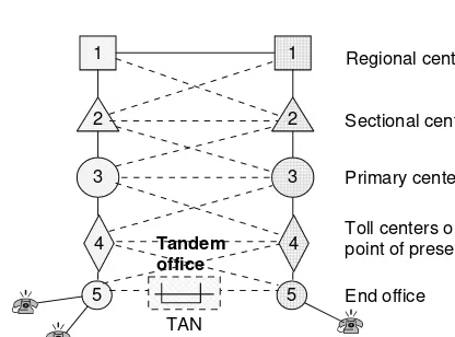
Fig. 1.3 Traditional communications hierarchy from access to core network
A tandem office provides connectivity between two low-end offices in the same local serving area avoiding toll centers.
1
2
3
4
5
1
2
3
4
5 End office
Toll centers or point of presence Primary center Sectional center Regional center
Tandem office
TAN
consisted of twisted pair (TP) copper and connected the end device, termed as plain old telephone service (POTS), with the nearest switching node (the end office or office level5) in an hierarchical architecture of switching nodes that makes up the entire communications network, Figs. 1.3, and 1.4. Up to the 1970s, each loop was able to transport low bandwidth bidirectional analog traffic up to 4 kHz, and the trunk was able to transport digital signals level 1, 2, or 3 (DS1 at 1.544 Mbps, DS2 at 6,312 Mbps, and DS3 at 44,736 Mbps); a similar network hierarchy existed in Europe and the rest of the world, although the signals had different bit rates, see Table 1.1.
Because of Ohm’s law, the resistance of the loop did not allow the distance of POTS from the end office to exceed 18 Kft with thin copper wires. In the United States, although copper loops up to 18 Kft were able to support POTS service for the majority of urban regions, they could not support POTS service in rural areas and in some suburbia. As a result, the pair-gain system was developed that was able to bring voice services to POTS located many kilometers far from the end office, Fig. 1.5.
Each POTS is associated with a calling number, and this is convenient to residential applications; the well-known Yellow Pages lists residential customers in an alphabetical order within a city serving
X
N A T 5
5 CityA
B y t i C
C y t i C PRI
3
X X
4 Toll
Toll
Comm hierarchy and networking
1.3 Voice and Data Networks 7
SWITCH
Distance is too long to support service
Many kilometers
Fig. 1.5Pair-gain systems also known as Subscriber Loop Carriers (SLC) have been very popular in the rural and suburbia United States, as well as in other countries
as a quick finder. Thus, the old paradigm has been one customer with one or two POTS, one entry in the list. However, imagine a small- or medium-size business with one dozen or more POTS. How convenient is this if all numbers are listed in the Yellow Pages? How easy is it to remember all these numbers? Would it not be better to remember one number only, and then dial an extension? This presented a business opportunity for a communications system that is now known aspublic business exchange(PBX). Thus, the PBX was not more than a low-cost small switching node that connected a small or medium business with the end office over a high-speed link (such as 1.544 Mbps).
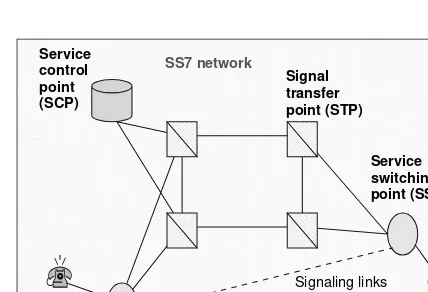
For the traditional network to be able to establish connectivity quickly, it consisted of dynamic switching nodes and an operations, administration, and management (OA&M) network layer. These nodes quickly connect inputs with outputs so that a complete end-to-end path is established by running a protocol known assignaling system 7(SS7) [23]. The signaling system 7 is a protocol specifically developed to establish connections (or call setup) across the public switch transport net-work (PSTN) and also terminate (or teardown) connections. SS7 starts from the end office and ends at the remote end office. SS7 uses its own digital network, which consists of three main functional nodes, theservice switching point(SSP), thesignal transfer point(STP), and theservice control point(SCP), Fig. 1.6.
• SSP nodes are the end or access offices in a network and they utilize common channel signaling (CCS); that is, a call processing protocol such as TR-303.
• STP nodes are points in the network where SS7 messages are received from a signaling link and are transferred to another link. STPs monitor messages and maintain connectivity (or routing) tables.
• SCPs are computers that maintain databases of the network; such databases are
• local number portability (LNP) • calling name database (CNAM) • home locations register (HLR) • line information database (LIDB)
• and more as SS7 has evolved to more advanced version to meet modern communication needs.
There are two STP types, national and gateway. National STPs transfer SS7 messages in the national network. Gateway STPs work with national and international protocols and transfer mes-sages from one to the other. In all, SS7 optimizes the digital network operations, is backward compat-ible with existing switches and meets future requirements, and it provides a reliable mechanism for data transfer without loss or duplication. Based on this, when connectivity is requested in the PSTN network, all switching nodes that are on the end-to-end path are dynamically provisioned, provided that nodes and bandwidth are available; according to SS7 instructions, a permanent connection is established until one of the end devices hangs up or connectivity termination is requested.
Although trunks that interconnect switching nodes transport DS1 and DS3 signals, these signals are demultiplexed down to the DS0 level when they reach a dynamic switch of the PSTN network. That is, PSTN dynamic switches are DS0 (digital service level 0 or 64 Kbps) and they operate on the time slot level.
In this digital PSTN, another type of switch exists; this is not dynamically provisioned according to SS7 but provisioned according to instructions by craft personnel either over the Ethernet (nodes have an Ethernet connectivity for remote provisioning and testing) or in situ (nodes also have a craft interface terminal (CIT) for provisioning and testing on location). These “static” switches are known as digital cross-connect systems (DACS or DCCS) and provide semipermanent connectivity to enterprise customers and at a higher level than DS0 (such as DS1 and DS3).
Both dynamic and DACS switches pass digital information without delay and buffering. This is an important characteristic of the legacy PSTN (including the more modern optical version) as compared with the current data network.
1.3.2 Data Networks and Protocols
1.3 Voice and Data Networks 9 transportable bandwidth opened a “never” enough appetite for bandwidth. Over the last two decades, the explosion of data transport created a data networking business and a successful data router indus-try. Based on specifically defined protocols packet transport any type of data, including digital voice and video from the data source to one or more destinations over the router-based data network.
As already described, routers store data first and then determine the best next router according to a router algorithm. Because of this, if we assume that there is a smart malicious program on it (that found its way in it hidden in one of the packets), then for as long as information data resides on the router, this program may access data, harvest information, and transmit it to an unauthorized destination. A different malicious program may also hide in the computer and execute itself according to a triggering mechanism such as a source address or destination address, a clock, and so on. Thus, the explosion of data networks and the rapid development and deployment of data protocols did not come for free; currently many security issues exist that are associated with software “viruses”, with “Trojan horses” and with many other malicious programs, in addition to a large class of irresponsible hackers who gain unauthorized access into computers, create havoc, and attempt illegal actions and also irresponsible data senders who broadcast all sort of unwanted e-mails, termed “spam”, and use unnecessarily network bandwidth. As a result, in just two decades of data networks existence, a whole new lexicon about such illegal and unauthorized actions has been created contrasted with traditional synchronous communication networks that for over a century had one term only, “eavesdropping”.
A data device generates large groups of bits or files, which are organized in packets to be trans-ported to a destination. Each bit in a packet is represented with one of two symbols, a logical one (1) or a logical zero (0), which in practice correspond to two voltage levels (in electrical transmission), 0 and+V (unipolar),−V and+V (bipolar), or (in optical transmission) presence of light and lack of light.
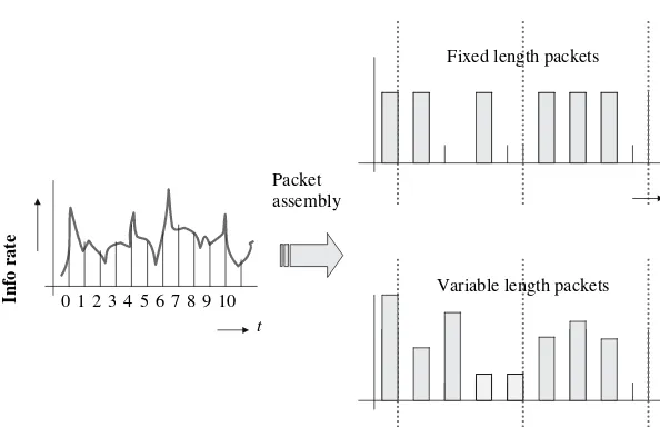
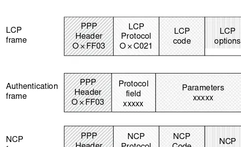
When packets are generated, they are not generated in a continuous and synchronous manner because files are not generated so. For example, when a “send file” command is issued, a string of packets is formed and transmitted. After that, there are no packets until a next command to send is issued. Thus, contrary to synchronous telephony for which bits are continuously generated and transmitted in a periodic manner, packets are generated sporadically without a predetermined periodicity. To make things more complicated, the generated packets depend on the particular data protocol and they may have a fixed length (such as ATM) or a variable length (such as TCP/IP), Fig. 1.7, and also differently defined overhead bytes because each data protocol is defined to meet specific requirements according to the application they were designed for. Thus, all data networks are not equal and so, there are ATM networks, Internet (IP) networks, frame relay networks, video ok (networks), and the list goes on, as compared with the hierarchical PSTN network, which is one.
1.3.3 Narrowband, Broadband, and Ultraband Services
t
Info rate 012345678910
Fixed length packets
Packet assembly
t
t
Variable length packets
Fig. 1.7 The data protocol determines one of two packetizing scenarios, packets with fixed length and packets with variable length
packets that are not accepted due to excessive noise and jitter and other signal distortions (attenua-tion, power level, pulse shape, modulation depth, and more).
Accordingly, a link is classified as narrowband, broadband, and ultraband and so are the services that can be offered over such links.
• Narrowband services are those that traditionally are 64 Kbps or less. Such services are voice, low-speed text, and telemetry and are supported by wired and wireless media (millions of voice channels when multiplexed are supported by fiber-optic media).
• Broadband services are typically those that traditionally are at 1.544 or 2.048 Mbps. Such services include multiple voice channels, compressed video, image, and high-speed data, and they are supported by wired, wireless, and fiber-optic media.
• Ultraband services are relatively new and they include high-quality video, interactive real-time video, super-computation, and a mix of many services to support multiplay. The data rate is Gbps and it is typically supported by optical media.
1.3.4 Circuit Switched Versus Store and Forward
The synchronous PSTN network as described in Sect.1.3.1 dedicates a well-defined path from source to destination, and the flow of information over the defined path is known with precision. That is, the loop number is known (all loops are numbered), the trunk number is known (all trunks are numbered), the input and output port at each circuit switching node is exactly known, and the time slots in multiplexed higher digital services (DS1, DS3, and so on) are exactly known. Each path is allocated during the call process by a number of protocols (such as TR-303) that run at the access nodes and also by SS7 that runs over the SS7 network, Fig. 1.8, as already discussed. One could say that as soon as the path is determined, a “pipe” has been formed that connects source with destination in which information flows end to end.
1.3 Voice and Data Networks 11
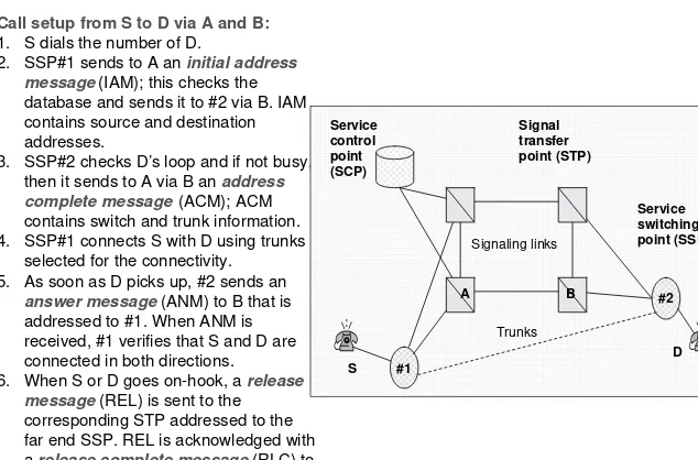
Call setup from S to D via A and B: 1. S dials the number of D.
2. SSP#1 sends to A an initial address message(IAM); this checks the database and sends it to #2 via B. IAM contains source and destination addresses.
3. SSP#2 checks D’s loop and if not busy, then it sends to A via B an address complete message(ACM); ACM contains switch and trunk information. 4. SSP#1 connects S with D using trunks
selected for the connectivity. 5. As soon as D picks up, #2 sends an
answer message(ANM) to B that is addressed to #1. When ANM is received, #1 verifies that S and D are connected in both directions. 6. When S or D goes on-hook, a release
message(REL) is sent to the corresponding STP addressed to the far end SSP. REL is acknowledged with arelease complete message(RLC) to STPs.
Fig. 1.8 Call setup using SS7
on source, destination, priority fields within the overhead of the packet and state of the data network. Thus, the “pipe” of the circuit switching network has no meaning here. Only in specific cases, the notion of “pipe” has meaning for which predefined routes are established for specific end users by provisioning routers on a predefined route. As a consequence, the store and forward network, in general, adds to the delay, and it cannot warranty real-time deliverability as the synchronous network can.
However, the amount of delay introduced by routers and data switches depends on the routing protocol and router technology. For example, the routing protocol may decide which the best next node is after taking into account the traffic and status parameters of all nodes in the network; this would introduce a significant delay due to intense processing. Another protocol may broadcast pack-ets to all neighboring nodes regardless of traffic and status and these nodes to their neighboring, and so on, so that packets will reach their destination expediently; this method would use bandwidth and resources unnecessarily. Another method may precompute the best possible routes to many desti-nations so that as soon as a packet arrives it relays it to the proper next node according to look-up tables, and so on; this is the fastest method, which depends on robustness and traffic congestion of the on the network.
In conclusion, the synchronous switched network is known for its reliability, real-time deliver-ability, super-high bandwidth, and security, whereas the traditional data network is known for its low-cost payload deliverability and ease of scalability. Thus, it is plausible that the next generation network should combine the strengths of both and at the same time eliminate or minimize their weaknesses, so that in the next generation network, nodes are
• characterized by real-time payload deliverability
• meet the performance that is commensurate with type of service • recognize different protocols
• meet the expected quality of service (QoS) • they restore the signal quality at their outputs • they are reliable
• they consume low power, and
Similarly, the overall network
• meets the expected performance • meets the expected availability • transports high and elastic bandwidth • it is protocol transparent
• it transports payload securely • it is reliable
• it is fault tolerant, and • it is cost-efficient.
1.3.5 Traffic and Service Evolution in Optical Networks
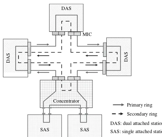
The 1980s witnessed the first optical data network and the first optical synchronous network, the Fiber Distributed Data Interface (FDDI) and the Synchronous Optical Network (SONET in the US) or Synchronous Digital Hierarchy (SDH in Europe), respectively. The first was a local area network (LAN) with a dual ring topology and the second a long-haul transport network that supported optical rings with optical add-drop multiplexing nodes topology as well as a point-to-point with optical add-drop multiplexing nodes. Since then, we have witnessed a rapid data network evolution with protagonists the Ethernet protocol and the Internet protocol, and to some extent the ATM, the Frame Relay and other protocols, each developed to meet different needs.
The interesting part in this is that although data networks are more cost-efficient, the optical network supports a humongous bandwidth, and thus even data over very long distances use optical network bandwidth; that is, despite the differences in cost structure, there is a symbiotic existence of both data and synchronous traffic: data needs the optical bandwidth, and optical bandwidth needs data to fill in the unused optical bandwidth. Thus, the next generation optical network, again, is a consequence of the traffic and services evolution.
1.3.6 Reliability of Optical Networks
The deployment of the optical synchronous network (SONET/SDH) has established an unprece-dented network reliability, switching protection, availability, unavailability, and performance. A per-formance at 10−12BER at data rates 2.5 Gbps for link lengths 50–80 km, a network unavailability
which is in seconds per year, and a switching protection which is better than 50 ms. However, SONET/SDH was neither based on the WDM dense ITU-T channel grid [25, 26] nor supported data rates at 10 and 40 Gbps, at an aggregate data rate per fiber exceeding Tbps. Therefore, the established metrics should be surpassed or be met in the next generation optical network.
To accomplish this, strong or moderate error correction techniques (such as forward error cor-rection or FEC) should be employed to compensate for performance degradation due to data rate increase, and the performance metrics (BER, SNR, Q-factor, signal power levels) of each channel needs to be monitored in service and in real time by sophisticated methods [27–32] and sophisticated reassignment strategies for channel protection and channel security need to be employed [33–38].
1.3.7 Security in Optical Networks
References 13 End-user data is most vulnerable as bad actors attempt to eavesdrop and harvest personal data. The protection of end-user data is typically the responsibility of the end user who employs encryp-tion algorithms and secret keys to transmit a ciphertext. However, the secret key needs to be distributed to the rightful recipient(s) to decode the ciphertext. Although data ciphering is the responsibility of the end user and it is transparent to network providers, the integrity of the key distribution method is a transmission issue.
Security of the link pertains to security of transmission paths throughout the network. The user trusts the network and expects data and key transported through it to be safe from unauthorized intrusions. Therefore, links should have sensing mechanisms to detect possible intrusions and also employ countermeasures.
Network security is related with security of nodes when they are managed and provisioned; typi-cally, a node is provisioned remotely over the Ethernet or Internet and thus it may fall victim to bad actors. Unauthorized access may alter the provisioning of a node to disable it, flood the network, harvest user information, deflect traffic to other destinations, or inject data and mimic a source. Harvested information may be calling numbers, traffic profiles, and so on. In data networks, har-vested information may be credit card numbers, bank accounts, client records and files, connectivity maps, and more. Typically, network security and data delivery assurance is the responsibility of the network provider.
Among the three media currently used in telecommunications, wireless, wired (twisted pair and coax), and fiber optic, the latter has inherently better security features because of the specialized knowledge required to access the medium. Wireless is the most insecure since electromagnetic waves reach both friendly and foe receivers, and thus, its security relies on features built in the authentication protocol and key hardness. The copper medium is easily tapped, but because it requires some effort, its security features may be placed between the wireless and optical; how-ever, eavesdropping is not unusual. Today attackers, hackers, and bad actors are well educated and therefore one cannot assure security by resting on the difficulty of tapping the fiber medium, on the difficulty of breaking the encryption code, or on the hardness of the authentication protocol, as eavesdroppers can harvest critical personal or national security information; they steal IDs, cause denial of service and in general generate havoc [40–43].
In Chap. 10, we examine encryption algorithms and network security in more detail.
References
1. C.E. Shannon, “A Mathematical Theory of Communication”, Bell System Technical Journal, 1948, pp. 379–423, 623–656.
2. ITU-T Recommendation G.711, “Pulse Code Modulation (PCM) of Voice Frequencies”, reprinted from the Blue Book, AT&T, Bell Laboratories.
3. ITU-T Recommendation G.704, “Synchronous Frame Structures used at 1544, 6312, 2048, 8488 and 44736 Kbps Hierarchical Levels”, 1995.
4. J.C. Bellamy,Digital Telephony, 3rd ed., Wiley, New York, 2000.
5. S.V. Kartalopoulos, “A Time Compression Multiplexing System for a Circuit Switched Digital Capability”,IEEE Transactions on Communications, vol. com-30, no.9, September 1982, pp. 2046–2052.
6. S.V. Kartalopoulos, “A Loop Access System for a Circuit Switched Digital Capability”, ISSLS 82, Toronto, Canada, September 20–24, 1982.
7. ITU-T Recommendation G.991.1, “High Bit Rate Digital Subscriber Line (HDSL) Transceivers”, October 1998. 8. ITU-T Recommendation G.991.2, “Single-Pair High-Speed Digital Subscriber Line (SHDSL) Transceivers”,
February 2001 and Amendment 1 (11/2001).
9. ITU-T Recommendation G.993.1, “Very High-Speed Digital Subscriber Line Foundation”, November 2001. 10. ITU-T Recommendation G.995.1, “Overview of Digital Subscriber Line (DSL) Recommendations”, February
2001, and Amendment 1 (11/2001).
11. R.E. Matick,Transmission Lines for Digital and Communication Networks, IEEE Press, 1995. 12. S.V. Kartalopoulos,DWDM: Networks, Devices and Technology, Wiley/IEEE, 2002.
15. S.V. Kartalopoulos, “Understanding SONET/SDH and ATM Networks”, IEEE Press, 1999. 16. ANSI T1.102-1993,Telecommunications–Digital Hierarchy—Electrical Interfaces, 1993. 17. ANSI T1.107-1988,Telecommunications–Digital Hierarchy—Formats Specifications, 1988.
18. ANSI T1.105.01-1994, Telecommunications–Synchronous Optical Network (SONET)—Automatic Protection Switching, 1994.
19. ANSI T1.105.03-1994,Telecommunications–Synchronous Optical Network (SONET)—Jitter at a Network Inter-faces, 1994.
20. ANSI T1.105.04-1994, Telecommunications–Synchronous Optical Network (SONET)—Data Communication Channel Protocols and Architectures, 1994.
21. ANSI T1.105.05-1994, Telecommunications–Synchronous Optical Network (SONET)—Tandem Connection Maintenance, 1994.
22. IETF RFC 2823, PPP over Simple Data Link (SDL) using SONET/SDH with ATM-like framing, May 2000. 23. T. Russell,Signaling System #7, 4th ed., McGraw Hill, New York, 2002.
24. N.F. Mir,Computer and Communications Networks, Prentice Hall, Englewood Cliffs, NJ, 2007.
25. ITU-T Recommendation G.694.1, “Spectral Grids for WDM Applications: DWDM Frequency Grid”, 5/2002. 26. ITU-T Recommendation G.694.2, “Spectral Grids for WDM Applications: CWDM Wavelength Grid”, 6/2002
Draft.
27. S.V. Kartalopoulos, “Fault Detectability in DWDM: Toward Higher Signal Quality and System Reliability”, IEEE Press, 2001.
28. S.V. Kartalopoulos, “Real-Time Estimation of BER & SNR in Optical Communications Channels”,Proceedings of SPIE Noise in Communication Systems, C.N. Georgiades and L.B. White, eds., vol. 5847, 2005, pp. 1–9. Also, invited paper at SPIE Fluctuation and Noise Symposium, May 24–26, 2005, Austin, TX.
29. S.V. Kartalopoulos, “Channel Error Estimation in Next Generation Optical Networks”, WSEAS Transactions on Circuits and Systems, vol. 3, No. 10, December 2004, pp. 2281–2284, ISSN 1109–2734, and ISBN 960-8457-06-8.
30. S.V. Kartalopoulos, “In-line Estimation of Optical BER & SNR”, SPIE Photon East, 10/23–26/05, Boston, MA, Track: “Optical Transmission Systems & Equipment for WDM Networks IV”, session 3, paper no. 6012–8, on CD-ROM: CDS194.
31. S.V. Kartalopoulos, “Circuit for Statistical Estimation of BER and SNR in Telecommunications”,Proceedings of 2006 IEEE International Symposium on Circuits and Systems (ISCAS 2006), May 21–24, 2006, Island of Kos, Greece, paper #A4L-K.2, CD-ROM, ISBN: 0-7803-9390-2, Library of Congress: 80–646530.
32. S.V. Kartalopoulos, “Method and Circuit for Statistical Estimation of Bit Error Rate and Signal to Noise Ratio based on Pulse Sampling for Optical Communications”, US Patent No. 7,149,661, December 2006.
33. S.V. Kartalopoulos, “Channel Protection with Real-Time and In-Service Performance Monitoring for Next Generation Secure WDM Networks”, ICC 2007 Computer and Communications Network Security Symposium, June 24–28, 2007.
34. S.V. Kartalopoulos, “Optical Network Security: Sensing Eavesdropper Intervention”, Globecom 2006, San Francisco, on CD-ROM, NIS03-2, ISBN: 1-4244-0357-X, ISSN: 1930-529X.
35. S.V. Kartalopoulos, “Optical Network Security: Countermeasures in View of Attacks”, SPIE European Symposium on Optics & Photonics in Security & Defense, Stockholm, Sweden, September 11–16, 2006, paper no. 6402–9, on CD-ROM, volumes 6394-6402.
36. S.V. Kartalopoulos, “Optical Network Security: Channel Signature ID”, Unclassified Proceedings of Milcom 2006, October 23–25, 2006, Washington, DC, on CD-ROM, ISBN 1-4244-0618-8, Library of Congress 2006931712, paper no. US-T-G-403.
37. S.V. Kartalopoulos, “Distinguishing Between Network Intrusion and Component Degradations in Optical Sys-tems and Networks”,WSEAS Transactions on Communications, vol. 4, No. 9, September 2005, pp. 1154–1161 38. S.V. Kartalopoulos, “Optical Network Security: Countermeasures in View of Channel Attacks”, Unclassified
Proceedings of Milcom 2006, October 23–25, 2006, Washington, DC, on CD-ROM, ISBN 1-4244-0618-8, Library of Congress 2006931712, paper no. US-T-G-404.
39. S.V. Kartalopoulos, Di Jin, “Vulnerability Assessment and Security of Scalable and Bandwidth Elastic Next Generation PONs”, Proceedings 11th WSEAS, July 23–28, 2007, Aghios Nikolaos, Crete, Greece,Advances in Communications, vol. 3, pp. 33–39.
40. S.V. Kartalopoulos, “Is Optical Quantum Cryptography the ‘Holly Grail’ of Secure Communication?”, SPIE Newsroom Magazine, April 2006, available at http://newsroom.spie.org/x2260.xml?highlight=x537.
41. S.V. Kartalopoulos, “Quantum Cryptography for Secure Optical Networks”, ICC 2007 Computer and Communications Network Security Symposium, June 24–28, 2007, on CD-ROM, ISBN 1-4244-0353-7 42. S.V. Kartalopoulos, “Communications Security: Biometrics over Communications Networks”, Globecom 2006,
San Francisco, on CD-ROM, NIS03-1, ISBN: 1-4244-0357-X, ISSN: 1930-529X.
Chapter 2
Digital Networks
2.1 Synchronous Optical Networks: SONET/SDH
2.1.1 Introduction
The development of solid-state lasers opened a new realm of possibilities with applications in man-ufacturing, consumer appliances, medicine, communications, and more. At the same time, optical fiber was developed (initially for medical endoscopes) that constrained light and guided it to travel for many kilometers and not in a straight path (with line of sight) within it. Put a modulated laser and an optical fiber together, and here is a transmission medium able to carry millions or trillions (or many more) of bits per second and over many kilometers. This capability, high data rate over very long distance, is impossible to be supported by any other technology and it was rightfully realized that optical technology offers to communications a tremendous potential to break the old telephony paradigm and support communication services that were and still are unimaginable.
In the 1980s, a new standardized protocol was introduced that defined the specifications of inter-faces, architecture and features of a synchronous optical network, which in the United States was called SONET and in Europe and elsewhere synchronous digital hierarchy (SDH); SONET and SDH were defined with enough differences to have two different standards issued as SONET by Telcordia (previously Bellcore) and SDH by ITU [1–16]. Since its introduction, the SONET/SDH network performed beyond expectation; it was quickly adopted by most advanced countries, and it became the de facto standard of optical networks. The reasons for this success were many:
• (glass) fiber as the transmission medium:
• exhibits high reliability (EMI, RFI, BER, etc.);
• transports megabits and gigabits per second, which is expandable to terabits; • links without repeaters that are many times longer (than twisted copper); • uses thinner cable (than twisted copper)/per GHz; and
• is easy to amplify, retime, and reshape.
• Standardized protocols allow for multi-vendor compatibility and interoperability.
• Technical personnel became well accustomed with the network and with maintenance procedures. • Although a young technology, it is future proofed and is expected to increase cost-efficiency as it matures. For example, the initial SONET/SDH did not include the OC-768 (40 Gbps) rate, which does now, and currently 100 Gbps is in the evaluating phase.
The set of SONET standard interfaces is the synchronous transport signal level-N(STS-N), whereN =1, 3, 12, 48, 192, and 768. The STS-Nrate on the optical medium is known asoptical
S. V. Kartalopoulos,Next Generation Intelligent Optical Networks, 15
C
Table 2.1 SONET and SDH rates
Signal designation Line rate (Mbps)
SONET SDH Optical
STS-1 STM-0 OC-1 51.84 (52 M)
STS-3 STM-1 OC-3 155.52 (155 M)
STS-12 STM-4 OC-12 622.08 (622 M)
STS-48 STM-16 OC-48 2,488.32 (2.5 G)
STS-192 STM-64 OC-192 9,953.28 (10 G)
STS-768 STM-256 OC-768 39,813.12 (40 G)
OC-N: optical carrier-levelN
STS-N: synchronous transport signal-levelN STM-N: synchronous transport module-levelN
carrier-N(OC-N), Table 2.1; STS-N whereN =1, 3, 12, 48, 192, and 768 indicates the bit rate of the electronic signal before the optical transmitter. The topology of the network is typically a protected ring with add-drop multiplexing (ADM) nodes or protected point-to-point with ADMs, Fig. 2.1; network nodes are known asnetwork elements(NE).
Similarly, the SDH set of standard interfaces is the synchronous transport module level-M (STM-M) whereM =0, 1, 4, 16, 64, and 256.
Both SONET and SDH define all layers, from the physical to the application. The physical trans-mission medium of both SONET and SDH is single-mode fiber (SMF). That, is, the SONET and SDH have many similarities and fewer differences. Some examples are the following:
• SONET and SDH are technically consistent;
• SONET and SDH rates and frame format are the same;
• SDH photonic interface specifies more parameters than SONET; and
• SONET and SDH standards have enough minor differences (technical and terminology) to add enough complexity (and cost) in designing hardware and software.
Both SONET and SDH carry all synchronous broadband rates (DS-n, E-n), asynchronous data (ATM), and well-known protocols (Internet, Ethernet, Frame Relay) encapsulated in ATM first and then mapped in SONET/SDH.
For maintenance, operations, administration, and management, the SONET/SDH defines three network layers: path, line, and section, Fig. 2.2
Fig. 2.1 Ring and point-to-point topologies supported by SONET/SDH
OC-192 OC-192
OC-48 OC-12
OADM Transceiver
Transceivers
Transceiver Net A
OC-48
Net B OC-192 OADM
Node
A
B
2.1 Synchronous Optical Networks: SONET/SDH 17
CPE=customer premises equipment LTE=line terminating equipment PTE=path terminating equipment
STE=section terminating equipment NE=network element
Fig. 2.2 Definition of path, line, and section in SONET/SDH Networks
Thepath layeraddresses issues related to transport of “services”, such as DS3, between path terminating network elements (PTE); that is, end to end.
The line layeraddresses issues related to the reliable transport of path layer payload and its overhead across the physical medium. It provides synchronization and multiplexing for the path layer network based on services provided by the section layer.
Thesection layeraddresses issues related to the transport of STS-N frames across the physi-cal medium, and it uses the services of the physiphysi-cal layer to form the physiphysi-cal transport. It constructs frames, scrambles payload, monitors errors, and much more.
2.1.2 SONET Frames
SONET/SDH (STS-N) frames come in specific sizes. However, regardless of size, a SONET/SDH frame is always transmitted in 125µs, and because of this, each STS-Nsignal has a specific bit rate (see Table 2.1).
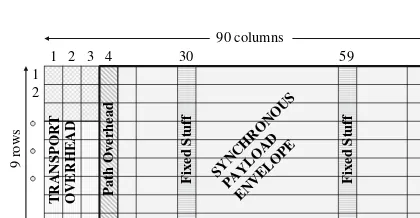
The smallest frame, STS-1, consists of a matrix of octets or bytes organized in 9 rows and 90 columns. This matrix or 9×90 is partitioned in two distinctive parts: the transport overhead of the first 3 columns and the synchronous payload envelope (SPE) of the remaining 87 columns, Fig. 2.3. An STS-Nframe is transmitted row by row, starting with the first octet (row 1, column 1). When the last octet of the first row is transmitted, it continues with the second row (row 2, column 1) and so on until it reaches the very last octet in the frame (in STS-1, this is row 9, column 90).
The SPE of an STS-1 consists of 87 columns; one column for the path overhead, two columns (columns 30 and 59) do not contain customer data, hence called “fixed stuff”, and 84 columns for
J1
User programmable. Sixty-four repeating bytes for receiving PTE to verify connectivity with transmitting PTE; default value=0×00
For error control. Calculated over all bits of previous SPE before scrambling
Indicates the construction of SPE. For example, asynchronous mapping, ATM, and so on
Indicates to the originating PTE the status and performance of the
terminating PTE
Allocated for end-user communication purposes
An end-to-end generalized multi-frame indicator for payloads (a pointer)
Z3 for future; no defined values
Z4 for future; no defined values
Z5 for future; no defined values
Fig. 2.4 Path overhead in SONET STS-1
customer data. That is, the upper bound efficiency of an STS-1 is 93.33 %. Nevertheless, the actual efficiency is mush less (about 60 %) because there is plenty of wasted bandwidth, as it will become evident.
Thepath overheadin an STS-1 frame consists of nine octets, and it is sourced and terminated by the path terminating equipment only. Each octet in it has a specific meaning, Fig. 2.4, although the working of each octet requires several contiguous frames to convey a complete message.
The transport overhead consists of two parts: the section overhead and the line overhead. The section overhead consists of row 1 to row 4 and column1 to column 3, Fig. 2.5:
• A1 and A2=framing pattern for each STS-1. Their hexadecimal value is 0×F628 {1111 0110 0010 1000}. A1, A2 arenotscrambled.
• C1=STS-1 ID. It is defined for each STS-1.
• B1=error monitoring. It is calculated over all bytes of the previous framebefore scramblingand placed in current framebefore scrambling.
• E1=a 64 Kbps voice communication channel; an STS-Nthat consists ofNSTS-1s; it is defined for the first (#1) STS-1 only.
• F1=to be used by section user.
• D1 to D3=a 192 Kbps communication channel between STEs for alarms, maintenance, control, monitoring, administration, and other needs; in STS-N, it is defined for #1 STS-1 only.
The line overhead consists of row 4 to row 9 and column 1 to column 3, Fig. 2.6.
BIP-8
2.1 Synchronous Optical Networks: SONET/SDH 19
Fig. 2.6 Line overhead in STS-1
• H1, H2=defines the offset between pointer and first SPE byte.
• H3 =it is called the action byte, and it is used for frequency justification in conjunction with the pointer bytes H1 and H2; if justification is negative, it carries valid payload; if positive or no justification, it is empty.
• BIP-8=error monitor. It is calculated over a previous STS-1 frame before scrambling, and it is placed in B2 before scrambling of current frame.
• K1 and K2=automatic protection switching (APS); in STS-N, it is defined for #1 STS-1 only. • D4 to D12 =this constitutes a 576 Kbps communication channel between LTEs for alarms,
maintenance, control, monitoring, administration, and other communication needs; in STS-N, it is defined for #1 STS-1 only.
• Z1 and Z2=not defined; in STS-N #3 STS-1, Z2 is defined as Line FEBE.
• E2=this is an express 64 Kbps communications channel between LTEs; in STS-N, it is defined for #1 STS-1 only.
Since the SONET/SDH frame generated in a network element (NE) may not be in complete synchronism (frequency and phase) with the incoming payload, there is an undetermined phase difference. To minimize latency, SONET/SDH follows the method of dynamic pointer that directly maps the incoming payload within the frame, the offset value (or phase difference from the sync) of which is measured and is incorporated in octets H1, H2, and H3 of the line overhead in every frame, Fig. 2.7.
Because the phase difference does not remain exactly the same over time, the H1 to H3 octets perform a dual function; they indicate the offset and they perform frequency justifications (i.e., corrections of frequency or offset variation). At start-up, the offset is calculated, and if the calcu-lated offset remains the same for three consecutive frames, a “no justification” is indicated. If the frequency slightly varies, then justification is performed, positive or negative; positive when the incoming rate is a little lower than the node clock and negative when the incoming rate is a little higher.