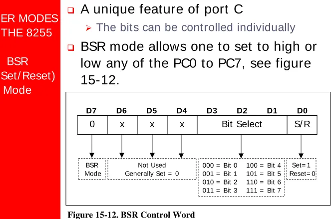
The 8051 Microcontroller and Embedded
Systems
Using Assembly and C
Second Edition
Muhammad Ali Mazidi Janice Gillispie Mazidi
Rolin D. McKinlay
CONTENTS
Introduction to Computing
The 8051 Microcontrollers
8051 Assembly Language Programming
Branch Instructions
I/O Port Programming
8051Addressing Modes
Arithmetic & Logic Instructions And Programs
8051 Programming in C
8051 Hardware Connection and Hex File
8051 Timer/Counter Programming in Assembly and C
8051 Serial Port Programming in Assembly and C
Interrupts Programming in Assembly and C
8051Interfacing to External Memory
8051 Real World Interfacing I: LCD,ADC AND SENSORS
LCD and KeyboardInterfacing
Chung-Ping Young
楊中平
I NTRODUCTI ON TO
COMPUTI NG
The 8051 Microcontroller and Embedded
Systems: Using Assembly and C
OUTLI NES
Numbering and coding systems
Digital primer
NUMBERI NG
AND CODI NG
SYSTEMS
Decimal and
Binary Number
Systems
Human beings use base 10 (
decimal
)
arithmetic
¾
There are 10 distinct symbols, 0, 1, 2,
…,
9
Computers use base 2 (
binary
) system
¾
There are only 0 and 1
¾
These two binary digits are commonly
NUMBERI NG
AND CODI NG
SYSTEMS
Converting
from Decimal
to Binary
Divide the decimal number by 2
repeatedly
Keep track of the remainders
Continue this process until the quotient
becomes zero
Write the remainders in reverse order
to obtain the binary number
Ex. Convert 25
10to binary
Quotient
Remainder
25/ 2 =
12
1
LSB (least significant bit)
12/ 2 =
6
0
6/ 2 =
3
0
3/ 2 =
1
1
NUMBERI NG
AND CODI NG
SYSTEMS
Converting
from Binary to
Decimal
Know the weight of each bit in a binary
number
Add them together to get its decimal
equivalent
Use the concept of weight to convert a
decimal number to a binary directly
Ex. Convert 11001
2to decimal
Weight:
2
42
32
22
12
0Digits:
1
1
0
0
1
Sum:
16 +
8 +
0 +
0 +
1 = 25
10Ex. Convert 39
10to binary
NUMBERI NG
AND CODI NG
SYSTEMS
Hexadecimal
System
Base 16, the
hexadecimal
system,
is used as a
convenient
representation of
binary numbers
¾
ex.
I t is much easier to
represent a string of 0s
and 1s such as
100010010110 as its
NUMBERI NG
AND CODI NG
SYSTEMS
Converting
between Binary
and Hex
To represent a binary number as its
equivalent hexadecimal number
¾
Start from the right and group 4 bits at a
time, replacing each 4-bit binary number
with its hex equivalent
To convert from hex to binary
¾
Each hex digit is replaced with its 4-bit
binary equivalent
Ex. Convert hex 29B to binary
2
9
B
Ex. Represent binary 100111110101 in hex
1001
1111
0101
NUMBERI NG
AND CODI NG
SYSTEMS
Converting
from Decimal
to Hex
Convert to binary first and then
convert to hex
Convert directly from decimal to hex
by repeated division, keeping track of
the remainders
Ex. Convert 45
10to hex
32
16
8
4
2
1
1 0 1 1 0 1
32 + 8 + 4 + 1 = 45
45
10= 0010 1101
2= 2D
16Ex. Convert 629
10to hex
512
256
128
64
32
16
8
4
2
1
1 0 0 1 1 1 0 1 0 1
NUMBERI NG
AND CODI NG
SYSTEMS
Converting
from Hex to
Decimal
Convert from hex to binary and then to
decimal
Convert directly from hex to decimal
by summing the weight of all digits
Ex. 6B2
16= 0110 1011 0010
21024
512
256
128
64
32
16
8
4
2
1
1
1 0 1 0 1 1 0 0 1 0
NUMBERI NG
AND CODI NG
SYSTEMS
Addition of Hex
Numbers
Adding the digits together from the
least significant digits
¾
I f the result is less than 16, write that digit
as the sum for that position
¾
I f it is greater than 16, subtract 16 from it
to get the digit and carry 1 to the next
digit
Ex. Perform hex addition: 23D9 + 94BE
23D9
LSD: 9 + 14 = 23
23 – 16 = 7 w/ carry
+ 94BE
1 + 13 + 11 = 25 25 – 16 = 9 w/ carry
NUMBERI NG
AND CODI NG
SYSTEMS
Subtraction of
Hex Numbers
I f the second digit is greater than the
first, borrow 16 from the preceding
digit
Ex. Perform hex subtraction: 59F – 2B8
59F
LSD: 15 – 8 = 7
NUMBERI NG
AND CODI NG
SYSTEMS
ASCI I Code
The ASCI I (pronounced
“
ask-E
”
) code
assigns binary patterns for
¾
Numbers 0 to 9
¾
All the letters of English alphabet,
uppercase and lowercase
¾
Many control codes and punctuation
marks
The ASCI I system uses 7 bits to
represent each code
y 79 Y 59 … ... ... ... d 64 D 44 c 63 C 43 b 62 B 42 a 61 A 41 Symbol Hex Symbol Hex
DI GI TAL
PRI MER
Binary Logic
Two voltage levels can be represented
as the two digits 0 and 1
Signals in digital electronics have two
distinct voltage levels with built-in
tolerances for variations in the voltage
A valid digital signal should be within
either of the two shaded areas
1
2
3
4
5
DI GI TAL
PRI MER
Logic Gates
AND gate
OR gate
Computer Science Illuminated, Dale and Lewis
DI GI TAL
PRI MER
Logic Gates
(cont’)
Tri-state buffer
I nverter
XOR gate
Computer Science Illuminated, Dale and LewisDI GI TAL
PRI MER
Logic Gates
(cont’)
NAND gate
NOR gate
DI GI TAL
PRI MER
Logic Design
Using Gates
Half adder
Full adder
DI GI TAL
PRI MER
Logic Design
Using Gates
(cont’)
4-bit adder
DI GI TAL
PRI MER
Logic Design
Using Gates
(cont’)
Decoders
¾
Decoders are widely used for address
decoding in computer design
Address decoder for 9 (1001
2)
The output will be 1 if and
only if the input is 1001
2Address decoder for 5 (0101
2)
The output will be 1 if and
only if the input is 0101
2DI GI TAL
PRI MER
Logic Design
Using Gates
(cont’)
Flip-flops
¾
Flip-flops are frequently used to store data
I NSI DE THE
COMPUTER
I mportant
Terminology
The unit of data size
¾
Bit
: a binary digit that can have the value
0 or 1
¾
Byte
: 8 bits
¾
Nibble
: half of a bye, or 4 bits
¾
Word
: two bytes, or 16 bits
The terms used to describe amounts of
memory in I BM PCs and compatibles
¾
Kilobyte
(K): 2
10bytes
¾
Megabyte
(M) : 2
20bytes, over 1 million
¾
Gigabyte
(G) : 2
30bytes, over 1 billion
I NSI DE THE
COMPUTER
I nternal
Organization of
Computers
CPU (Central Processing Unit)
¾
Execute information stored in memory
I / O (I nput/ output) devices
¾
Provide a means of communicating with
CPU
Memory
¾
RAM (Random Access Memory)
–
temporary storage of programs that
computer is running
The data is lost when computer is off
¾
ROM (Read Only Memory)
–
contains
programs and information essential to
operation of the computer
The information cannot be changed by use,
and is not lost when power is off
I NSI DE THE
COMPUTER
I nternal
Organization of
Computers
(cont’)
CPU
Memory
(RAM, ROM)
Peripherals
(monitor,
printer, etc.)
Address bus
I NSI DE THE
COMPUTER
I nternal
Organization of
Computers
(cont’)
The CPU is connected to memory and
I / O through strips of wire called a
bus
¾
Carries information from place to place
Address bus
Data bus
Control bus
CPU
Read/ Write
RAM
Address bus
Data bus
ROM
Printer
Disk
MonitorKeyboard
I NSI DE THE
COMPUTER
I nternal
Organization of
Computers
(cont’)
Address bus
¾
For a device (memory or I / O) to be
recognized by the CPU, it must be
assigned an address
The address assigned to a given device must
be unique
The CPU puts the address on the address bus,
and the decoding circuitry finds the device
Data bus
¾
The CPU either gets data from the device
or sends data to it
Control bus
¾
Provides read or write signals to the
I NSI DE THE
COMPUTER
More about
Data Bus
The more data buses available, the
better the CPU
¾
Think of data buses as highway lanes
More data buses mean a more
expensive CPU and computer
¾
The average size of data buses in CPUs
varies between 8 and 64
Data buses are bidirectional
¾
To receive or send data
I NSI DE THE
COMPUTER
More about
Address Bus
The more address buses available, the
larger the number of devices that can
be addressed
The number of locations with which a
CPU can communicate is always equal
to 2
x
, where
x
is the address lines,
regardless of the size of the data bus
¾
ex. a CPU with 24 address lines and 16
data lines can provide a total of 2
24or 16M
bytes of addressable memory
¾
Each location can have a maximum of 1
byte of data, since all general-purpose
CPUs are
byte addressable
I NSI DE THE
COMPUTER
CPU’s Relation
to RAM and
ROM
For the CPU to process information,
the data must be stored in RAM or
ROM, which are referred to as
primary
memory
ROM provides information that is fixed
and permanent
¾
Tables or initialization program
RAM stores information that is not
permanent and can change with time
¾
Various versions of OS and application
packages
¾
CPU gets information to be processed
first form RAM (or ROM)
I NSI DE THE
COMPUTER
I nside CPUs
Registers
¾
The CPU uses registers to store
information temporarily
Values to be processed
Address of value to be fetched from memory
¾
I n general, the more and bigger the
registers, the better the CPU
Registers can be 8-, 16-, 32-, or 64-bit
I NSI DE THE
COMPUTER
I nside CPUs
(cont’)
Flags
ALU
Program Counter
Instruction Register
Instruction decoder,
timing, and control
Register A
Register B
Register C
Register D
Address Bus
C
ontrol Bus
Data Bus
I NSI DE THE
COMPUTER
I nside CPUs
(cont’)
ALU (arithmetic/ logic unit)
¾
Performs arithmetic functions such as add,
subtract, multiply, and divide, and logic
functions such as AND, OR, and NOT
Program counter
¾
Points to the address of the next
instruction to be executed
As each instruction is executed, the program
counter is incremented to point to the address
of the next instruction to be executed
I nstruction decoder
¾
I nterprets the instruction fetched into the
CPU
A CPU capable of understanding more
I NSI DE THE
COMPUTER
I nternal
Working of
Computers
Ex. A CPU has registers A, B, C, and D and it has an 8-bit
data bus and a 16-bit address bus. The CPU can access
memory from addresses 0000 to FFFFH
Assume that the code for the CPU to move a value to
register A is B0H and the code for adding a value to
register A is 04H
The action to be performed by the CPU is to put 21H into
register A, and then add to register A values 42H and 12H
I NSI DE THE
COMPUTER
I nternal
Working of
Computers
(cont’)
Ex. (cont’)
Action
Code
Data
Move value 21H into reg. A B0H 21H
Add value 42H to reg. A 04H 42H
Add value 12H to reg. A 04H 12H
Mem. addr. Contents of memory address
1400 (B0) code for moving a value to register A 1401 (21) value to be moved
1402 (04) code for adding a value to register A 1403 (42) value to be added
1404 (04) code for adding a value to register A 1405 (12) value to be added
1406 (F4) code for halt
I NSI DE THE
COMPUTER
I nternal
Working of
Computers
(cont’)
Ex. (cont’)
The actions performed by CPU are as follows:
1.
The program counter is set to the value 1400H,
indicating the address of the first instruction code to
be executed
2.
¾
The CPU puts 1400H on address bus and sends it
out
The memory circuitry finds the location
¾
The CPU activates the READ signal, indicating to
memory that it wants the byte at location 1400H
This causes the contents of memory location1400H, which is B0, to be put on the data bus and brought into the CPU
...
I NSI DE THE
COMPUTER
I nternal
Working of
Computers
(cont’)
Ex. (cont’)
3.
¾
The CPU decodes the instruction B0
¾
The CPU commands its controller circuitry to bring
into register A of the CPU the byte in the next
memory location
The value 21H goes into register A
¾
The program counter points to the address of the
next instruction to be executed, which is 1402H
Address 1402 is sent out on the address bus tofetch the next instruction
I NSI DE THE
COMPUTER
I nternal
Working of
Computers
(cont’)
Ex. (cont’)
4.
¾
From memory location 1402H it fetches code 04H
¾
After decoding, the CPU knows that it must add to
the contents of register A the byte sitting at the
next address (1403)
¾
After the CPU brings the value (42H), it provides
the contents of register A along with this value to
the ALU to perform the addition
I t then takes the result of the addition from the ALU’s output and puts it in register A
The program counter becomes 1404, the address of the next instruction
I NSI DE THE
COMPUTER
I nternal
Working of
Computers
(cont’)
Ex. (cont’)
5.
¾
Address 1404H is put on the address bus and the
code is fetched into the CPU, decoded, and
executed
This code is again adding a value to register A The program counter is updated to 1406H 6.
¾
The contents of address 1406 are fetched in and
executed
¾
This HALT instruction tells the CPU to stop
Chung-Ping Young
楊中平
8051 MI CROCONTROLLERS
The 8051 Microcontroller and Embedded
Systems: Using Assembly and C
OUTLI NES
Microcontrollers and embedded
processors
MI
CRO-CONTROLLERS
AND
EMBEDDED
PROCESSORS
Microcontroller
vs.
General-Purpose
Microprocessor
General-purpose microprocessors
contains
¾
No RAM
¾
No ROM
¾
No I / O ports
Microcontroller has
¾
CPU (microprocessor)
¾
RAM
¾
ROM
¾
I / O ports
¾
Timer
MI
CRO-CONTROLLERS
AND
EMBEDDED
PROCESSORS
Microcontroller
vs.
General-Purpose
Microprocessor
(cont’)
Serial
COM
Timer
I/O
ROM
RAM
CPU
MicrocontrollerCPU
RAM
Address bus
Data bus
ROM
I/O
Port
Serial COM
Port
Timer
MI
CRO-CONTROLLERS
AND
EMBEDDED
PROCESSORS
Microcontroller
vs.
General-Purpose
Microprocessor
(cont’)
General-purpose microprocessors
¾
Must add RAM, ROM, I / O ports, and
timers externally to make them functional
¾
Make the system bulkier and much more
expensive
¾
Have the advantage of versatility on the
amount of RAM, ROM, and I / O ports
Microcontroller
¾
The fixed amount of on-chip ROM, RAM,
and number of I / O ports makes them ideal
for many applications in which cost and
space are critical
MI
CRO-CONTROLLERS
AND
EMBEDDED
PROCESSORS
Microcontrollers
for Embedded
Systems
An embedded product uses a
microprocessor (or microcontroller) to
do one task and one task only
¾
There is only one application software that
is typically burned into ROM
A PC, in contrast with the embedded
system, can be used for any number of
applications
¾
I t has RAM memory and an operating
system that loads a variety of applications
into RAM and lets the CPU run them
¾
A PC contains or is connected to various
embedded products
MI
CRO-CONTROLLERS
AND
EMBEDDED
PROCESSORS
Microcontrollers
for Embedded
Systems
(cont’)
Home
¾
Appliances, intercom, telephones, security systems,
garage door openers, answering machines, fax
machines, home computers, TVs, cable TV tuner,
VCR, camcorder, remote controls, video games,
cellular phones, musical instruments, sewing
machines, lighting control, paging, camera, pinball
machines, toys, exercise equipment
Office
¾
Telephones, computers, security systems, fax
machines, microwave, copier, laser printer, color
printer, paging
Auto
MI
CRO-CONTROLLERS
AND
EMBEDDED
PROCESSORS
x86 PC
Embedded
Applications
Many manufactures of general-purpose
microprocessors have targeted their
microprocessor for the high end of the
embedded market
¾
There are times that a microcontroller is
inadequate for the task
When a company targets a
general-purpose microprocessor for the
embedded market, it optimizes the
processor used for embedded systems
Very often the terms
embedded
MI
CRO-CONTROLLERS
AND
EMBEDDED
PROCESSORS
x86 PC
Embedded
Applications
(cont’)
One of the most critical needs of an
embedded system is to decrease
power consumption and space
I n high-performance embedded
processors, the trend is to integrate
more functions on the CPU chip and let
designer decide which features he/ she
wants to use
I n many cases using x86 PCs for the
high-end embedded applications
¾
Saves money and shortens development
time
A vast library of software already written
MI
CRO-CONTROLLERS
AND
EMBEDDED
PROCESSORS
Choosing a
Microcontroller
8-bit microcontrollers
¾
Motorola’s 6811
¾
I ntel’s 8051
¾
Zilog’s Z8
¾
Microchip’s PI C
There are also 16-bit and 32-bit
MI
CRO-CONTROLLERS
AND
EMBEDDED
PROCESSORS
Criteria for
Choosing a
Microcontroller
Meeting the computing needs of the
task at hand efficiently and cost
effectively
¾
Speed
¾
Packaging
¾
Power consumption
¾
The amount of RAM and ROM on chip
¾
The number of I / O pins and the timer on
chip
¾
How easy to upgrade to
higher-performance or lower power-consumption
versions
MI
CRO-CONTROLLERS
AND
EMBEDDED
PROCESSORS
Criteria for
Choosing a
Microcontroller
(cont’)
Availability of software development
tools, such as compilers, assemblers,
and debuggers
Wide availability and reliable sources
of the microcontroller
¾
The 8051 family has the largest number of
diversified (multiple source) suppliers
I ntel (original)
Atmel
Philips/ Signetics
AMD
I nfineon (formerly Siemens)
Matra
OVERVI EW OF
8051 FAMI LY
8051
Microcontroller
I ntel introduced 8051, referred as
MCS-51, in 1981
¾
The 8051 is an 8-bit processor
The CPU can work on only 8 bits of data at a
time
¾
The 8051 had
128 bytes of RAM
4K bytes of on-chip ROM
Two timers
One serial port
Four I / O ports, each 8 bits wide
6 interrupt sources
OVERVI EW OF
8051 FAMI LY
8051
Microcontroller
(cont’)
Interrupt
Control
Bus
Control
CPU
OSC
I/O
Ports
Serial
Port
Etc.
Timer 0
Timer 1
On-chip
RAM
On-chip
ROM
for code
P0 P1 P2 P3
Address/Data
TXD RXD
Counter Inputs
OVERVI EW OF
8051 FAMI LY
8051 Family
The 8051 is a subset of the 8052
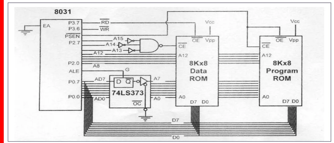
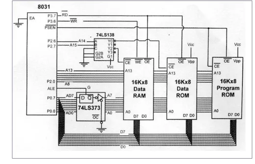
The 8031 is a ROM-less 8051
¾
Add external ROM to it
¾
You lose two ports, and leave only 2 ports
for I / O operations
6
8
6
I nterrupt sources
1
1
1
Serial port
32
32
32
I / O pins
2
3
2
Timers
128
256
128
RAM (bytes)
0K
8K
4K
ROM (on-chip program
space in bytes)
8031
8052
OVERVI EW OF
8051 FAMI LY
Various 8051
Microcontrollers
8751 microcontroller
¾
UV-EPROM
PROM burner
UV-EPROM eraser takes 20 min to erase
AT89C51 from
Atmel Corporation
¾
Flash (erase before write)
ROM burner that supports flash
A separate eraser is not needed
DS89C4x0 from
Dallas Semiconductor
,
now part of
Maxim Corp.
¾
Flash
OVERVI EW OF
8051 FAMI LY
Various 8051
Microcontrollers
(cont’)
DS5000 from
Dallas Semiconductor
¾
NV-RAM (changed one byte at a time),
RTC (real-time clock)
Also comes with on-chip loader
OTP (one-time-programmable) version
of 8051
8051 family from
Philips
¾
ADC, DAC, extended I / O, and both OTP
Chung-Ping Young
楊中平
8051 ASSEMBLY
LANGUAGE
PROGRAMMI NG
The 8051 Microcontroller and Embedded
Systems: Using Assembly and C
I NSI DE THE
8051
Registers
Register are used to store information
temporarily, while the information
could be
¾
a byte of data to be processed, or
¾
an address pointing to the data to be
fetched
The vast majority of 8051 register are
8-bit registers
I NSI DE THE
8051
Registers
(cont’)
The 8 bits of a register are shown from
MSB D7 to the LSB D0
¾
With an 8-bit data type, any data larger
than 8 bits must be broken into 8-bit
chunks before it is processed
D0 D1
D2 D3
D4 D5
D6 D7
8 bit Registers
most
significant bit
I NSI DE THE
8051
Registers
(cont’)
The most widely used registers
¾
A (Accumulator)
For all arithmetic and logic instructions
¾
B, R0, R1, R2, R3, R4, R5, R6, R7
¾
DPTR (data pointer), and PC (program
counter)
R6 R5 R4 R3 R2 R1 R0 B A
R7
DPTR
I NSI DE THE
8051
MOV
I nstruction
MOV destination, source
; copy source to dest.
¾
The instruction tells the CPU to move (in reality,
COPY
) the source operand to the destination
operand
MOV A,
#
55H ;load value 55H into reg. A
MOV R0,A ;copy contents of A into R0
;(now A=R0=55H)
MOV R1,A ;copy contents of A into R1
;(now A=R0=R1=55H)
MOV R2,A ;copy contents of A into R2
;(now A=R0=R1=R2=55H)
MOV R3,#95H ;load value 95H into R3
;(now R3=95H)
MOV A,R3 ;copy contents of R3 into A
;now A=R3=95H
I NSI DE THE
8051
MOV
I nstruction
(cont’)
Notes on programming
¾
Value (proceeded with # ) can be loaded
directly to registers A, B, or R0 – R7
MOV
A,
#
23H
MOV R5, #
0
F9H
¾
I f values 0 to F moved into an 8-bit
register, the rest of the bits are assumed
all zeros
“
MOV A, #5
” , the result will be A= 05; i.e., A
= 00000101 in binary
¾
Moving a value that is too large into a
register will cause an error
MOV A, #7F2H
; I LLEGAL: 7F2H> 8 bits (FFH)
If it’s not preceded with #,
it means to load from a
memory location
I NSI DE THE
8051
ADD
I nstruction
ADD A, source
; ADD the source operand
; to the accumulator
¾
The
ADD
instruction tells the CPU to add the source
byte to register A and put the result in register A
¾
Source operand can be either a register or
immediate data, but the destination must always
be register A
“ADD R4, A
” and “ADD R2, #12H
” are invalid since A must be the destination of any arithmetic operationMOV A, #25H
;load 25H into A
MOV R2, #34H
;load 34H into R2
ADD A, R2 ;add R2 to Accumulator
;(A = A + R2)
MOV A, #25H
;load one operand
;into A (A=25H)
Structure of
Assembly
Language
I n the early days of the computer,
programmers coded in
machine language
,
consisting of 0s and 1s
¾
Tedious, slow and prone to error
Assembly languages
, which provided
mnemonics for the machine code instructions,
plus other features, were developed
¾
An Assembly language program consist of a series
of lines of Assembly language instructions
Assembly language is referred to as a
low-level language
¾
I t deals directly with the internal structure of the
CPU
Structure of
Assembly
Language
8051
ASSEMBLY
PROGRAMMI NG
Assembly language instruction includes
¾
a mnemonic
(abbreviation easy to remember)
the commands to the CPU, telling it what those
to do with those items
¾
optionally followed by one or two operands
the data items being manipulated
A given Assembly language program is
a series of statements, or lines
¾
Assembly language instructions
Tell the CPU what to do
¾
Directives (or pseudo-instructions)
Structure of
Assembly
Language
ORG 0H
;start(origin) at location
0
MOV R5, #25H
;load 25H into R5
MOV R7, #34H
;load 34H into R7
MOV A, #0
;load 0 into A
ADD A, R5
;add contents of R5 to A
;now A = A + R5
ADD A, R7
;add contents of R7 to A
;now A = A + R7
ADD A, #12H
;add to A value 12H
;now A = A + 12H
HERE: SJMP HERE ;stay in this loop
END
;end of asm source file
8051
ASSEMBLY
PROGRAMMI NG
An Assembly language instruction
consists of four fields:
[label:] Mnemonic [operands] [;comment]
Mnemonics
produce
opcodes
The label field allows
the program to refer to a
Comments may be at the end of a
line or on a line by themselves
The assembler ignores comments
ASSEMBLI NG
AND RUNNI NG
AN 8051
PROGRAM
The step of Assembly language
program are outlines as follows:
1)
First we use an editor to type a program,
many excellent editors or word
processors are available that can be used
to create and/ or edit the program
Notice that the editor must be able to produce
an ASCI I file
ASSEMBLI NG
AND RUNNI NG
AN 8051
PROGRAM
(cont’)
2)
The
“asm
”
source file containing the
program code created in step 1 is fed to
an 8051 assembler
The assembler converts the instructions into
machine code
The assembler will produce an object file and
a list file
The extension for the object file is
“
obj
”
while
the extension for the list file is
“
lst
”
3)
Assembler require a third step called
linking
The linker program takes one or more object
code files and produce an absolute object file
with the extension
“
abs
”
ASSEMBLI NG
AND RUNNI NG
AN 8051
PROGRAM
(cont’)
4)
Next the
“abs
”
file is fed into a program
called
“OH”
(object to hex converter)
which creates a file with extension
“hex”
that is ready to burn into ROM
This program comes with all 8051 assemblers
ASSEMBLI NG
AND RUNNI NG
AN 8051
PROGRAM
Steps to Create
a Program
EDITOR
PROGRAM
ASSEMBLER
PROGRAM
LINKER
PROGRAM
OH
PROGRAM
myfile.asm
myfile.obj
myfile.abs myfile.lst
ASSEMBLI NG
AND RUNNI NG
AN 8051
PROGRAM
lst File
The lst (list) file, which is optional, is
very useful to the programmer
¾
I t lists all the opcodes and addresses as
well as errors that the assembler detected
¾
The programmer uses the lst file to find
the syntax errors or debug
1 0000 ORG 0H ;start (origin) at 0
2 0000 7D25 MOV R5,#25H ;load 25H into R5 3 0002 7F34 MOV R7,#34H ;load 34H into R7 4 0004 7400 MOV A,#0 ;load 0 into A
5 0006 2D ADD A,R5 ;add contents of R5 to A ;now A = A + R5
6 0007 2F ADD A,R7 ;add contents of R7 to A ;now A = A + R7
PROGRAM
COUNTER AND
ROM SPACE
Program
Counter
The program counter points to the
address of the next instruction to be
executed
¾
As the CPU fetches the opcode from the
program ROM, the program counter is
increasing to point to the next instruction
The program counter is 16 bits wide
¾
This means that it can access program
PROGRAM
COUNTER AND
ROM SPACE
Power up
All 8051 members start at memory
address 0000 when they’re powered
up
¾
Program Counter has the value of 0000
¾
The first opcode is burned into ROM
address 0000H, since this is where the
8051 looks for the first instruction when it
is booted
PROGRAM
COUNTER AND
ROM SPACE
Placing Code in
ROM
Examine the list file and how the code
is placed in ROM
1 0000 ORG 0H ;start (origin) at 0 2 0000 7D25 MOV R5,#25H ;load 25H into R5 3 0002 7F34 MOV R7,#34H ;load 34H into R7 4 0004 7400 MOV A,#0 ;load 0 into A
5 0006 2D ADD A,R5 ;add contents of R5 to A ;now A = A + R5
6 0007 2F ADD A,R7 ;add contents of R7 to A ;now A = A + R7
7 0008 2412 ADD A,#12H ;add to A value 12H ;now A = A + 12H 8 000A 80EF HERE: SJMP HERE ;stay in this loop
9 000C END ;end of asm source file
ADD A, # 12H 2412
0008
ADD A, R7 2F
0007
ADD A, R5 2D
0006
MOV A, # 0 7400
0004
MOV R7, # 34H 7F34
0002
MOV R5, # 25H 7D25
0000
Assembly Language Machine Language
PROGRAM
COUNTER AND
ROM SPACE
Placing Code in
ROM
(cont’)
After the program is burned into ROM,
the opcode and operand are placed in
ROM memory location starting at 0000
80 000A
12 0009
24 0008
2F 0007
2D 0006
00 0005
74 0004
34 0003
7F 0002
25 0001
7D 0000
Code
Address
PROGRAM
COUNTER AND
ROM SPACE
Executing
Program
A step-by-step description of the
action of the 8051 upon applying
power on it
1.
When 8051 is powered up, the PC has
0000 and starts to fetch the first opcode
from location 0000 of program ROM
Upon executing the opcode 7D, the CPU
fetches the value 25 and places it in R5
Now one instruction is finished, and then the
PC is incremented to point to 0002, containing
opcode 7F
2.
Upon executing the opcode 7F, the value
34H is moved into R7
PROGRAM
COUNTER AND
ROM SPACE
Executing
Program
(cont’)
(cont’)
3.
The instruction at location 0004 is
executed and now PC = 0006
4.
After the execution of the 1-byte
instruction at location 0006, PC = 0007
5.
Upon execution of this 1-byte instruction
at 0007, PC is incremented to 0008
This process goes on until all the instructions
are fetched and executed
PROGRAM
COUNTER AND
ROM SPACE
ROM Memory
Map in 8051
Family
No member of 8051 family can access
more than 64K bytes of opcode
¾
The program counter is a 16-bit register
Byte Byte Byte
0000
0FFF
0000 0000
3FFF
7FFF 8751
AT89C51
DS89C420/30
8051 DATA
TYPES AND
DI RECTI VES
Data Type
8051 microcontroller has only one data
type - 8 bits
¾
The size of each register is also 8 bits
¾
I t is the job of the programmer to break
down data larger than 8 bits (00 to FFH,
or 0 to 255 in decimal)
8051 DATA
TYPES AND
DI RECTI VES
Assembler
Directives
The
DB
directive is the most widely
used data directive in the assembler
¾
I t is used to define the 8-bit data
¾
When
DB
is used to define data, the
numbers can be in decimal, binary, hex,
ASCI I formats
ORG
500H
DATA1: DB
28
;DECIMAL (1C in Hex)
DATA2: DB
00110101B
;BINARY (35 in Hex)
DATA3: DB
39H
;HEX
ORG
510H
DATA4: DB
“2591”
;ASCII NUMBERS
ORG 518H
DATA6: DB
“My name is Joe”
;ASCII CHARACTERS
The “D” after the decimal
number is optional, but using
“B” (binary) and “H”
(hexadecimal) for the others is
required
The Assembler will
convert the numbers
into hex
Place ASCII in quotation marks
The Assembler will assign ASCII
code for the numbers or characters
8051 DATA
TYPES AND
DI RECTI VES
Assembler
Directives
(cont’)
ORG
(origin)
¾
The
ORG
directive is used to indicate the
beginning of the address
¾
The number that comes after
ORG
can be
either in hex and decimal
I f the number is not followed by H, it is decimal
and the assembler will convert it to hex
END
¾
This indicates to the assembler the end of
the source (asm) file
¾
The
END
directive is the last line of an
8051 program
Mean that in the code anything after the
END
8051 DATA
TYPES AND
DI RECTI VES
Assembler
directives
(cont’)
EQU
(equate)
¾
This is used to define a constant without
occupying a memory location
¾
The
EQU
directive does not set aside
storage for a data item but associates a
constant value with a data label
8051 DATA
TYPES AND
DI RECTI VES
Assembler
directives
(cont’)
EQU
(equate)
(cont’)
¾
Assume that there is a constant used in
many different places in the program, and
the programmer wants to change its value
throughout
By the use of
EQU
, one can change it once and
the assembler will change all of its occurrences
COUNT
EQU 25
...
....
MOV
R3, #COUNT
Use
EQU
for the
counter constant
FLAG BI TS AND
PSW REGI STER
Program Status
Word
The program status word (PSW)
register, also referred to as the
flag
register
, is an 8 bit register
¾
Only 6 bits are used
These four are CY (
carry
), AC (
auxiliary carry
), P
(
parity
), and OV (
overflow
)
–
They are called
conditional flags
, meaning
that they indicate some conditions that
resulted after an instruction was executed
The PSW3 and PSW4 are designed as RS0 and
RS1, and are used to change the bank
FLAG BI TS AND
PSW REGI STER
Program Status
Word
(cont’)
P
--OV
RS0
RS1
F0
AC
CY
CY PSW.7 Carry flag.
AC PSW.6 Auxiliary carry flag.
--
PSW.5 Available to the user for general purpose
RS1 PSW.4 Register Bank selector bit 1.
RS0 PSW.3 Register Bank selector bit 0.
OV PSW.2 Overflow flag.
--
PSW.1 User definable bit.
P PSW.0 Parity flag. Set/cleared by hardware each
instruction cycle to indicate an odd/even
number of 1 bits in the accumulator.
10H – 17H 2
0 1
08H – 0FH 1
1 0
00H – 07H 0 0 0 Address Register Bank RS0 RS1
Carry out from the d7 bit
A carry from D3 to D4
Reflect the number of 1s
in register A
FLAG BI TS AND
PSW REGI STER
ADD
I nstruction And
PSW
X MOV C, bit
X ORL C, / bit
X ORL C, bit
X ANL C, / bit
X ANL C, bit
X CPL C 0 CLR C 1 SETB C X PLC X RPC X DA X 0 DI V X 0 MUL X X X SUBB X X X ADDC X X X ADD AC OV CY I nstruction
FLAG BI TS AND
PSW REGI STER
ADD
I nstruction And
PSW
(cont’)
Example 2-2
Show the status of the CY, AC and P flag after the addition of 38H
and 2FH in the following instructions.
MOV A, #38H
ADD A, #2FH ;after the addition A=67H, CY=0
Solution:
38 00111000
+ 2F
00101111
67 01100111
CY = 0 since there is no carry beyond the D7 bit
AC = 1 since there is a carry from the D3 to the D4 bi
FLAG BI TS AND
PSW REGI STER
ADD
I nstruction And
PSW
(cont’)
Example 2-3
Show the status of the CY, AC and P flag after the addition of 9CH
and 64H in the following instructions.
MOV A, #9CH
ADD A, #64H ;after the addition A=00H, CY=1
Solution:
9C 10011100
+ 64
01100100
100 00000000
CY = 1 since there is a carry beyond the D7 bit
AC = 1 since there is a carry from the D3 to the D4 bi
FLAG BI TS AND
PSW REGI STER
ADD
I nstruction And
PSW
(cont’)
Example 2-4
Show the status of the CY, AC and P flag after the addition of 88H
and 93H in the following instructions.
MOV A, #88H
ADD A, #93H ;after the addition A=1BH, CY=1
Solution:
88 10001000
+ 93
10010011
11B 00011011
CY = 1 since there is a carry beyond the D7 bit
AC = 0 since there is no carry from the D3 to the D4 bi
REGI STER
BANKS AND
STACK
RAM Memory
Space
Allocation
There are 128 bytes of RAM in the
8051
¾
Assigned addresses 00 to 7FH
The 128 bytes are divided into three
different groups as follows:
1)
A total of 32 bytes from locations 00 to
1F hex are set aside for register banks
and the stack
2)
A total of 16 bytes from locations 20H to
2FH are set aside for bit-addressable
read/ write memory
3)
A total of 80 bytes from locations 30H to
8051
REGI STER
BANKS AND
STACK
RAM Memory
Space
Allocation
(cont’)
Scratch pad RAM
Bit-Addressable RAM
Register Bank 3
Register Bank 2
Register Bank 1 (stack)
Register Bank 0 07
08 0F 10 17 18 1F 20 2F 30 7F
8051
REGI STER
BANKS AND
STACK
Register Banks
These 32 bytes are divided into 4
banks of registers in which each bank
has 8 registers, R0-R7
¾
RAM location from 0 to 7 are set aside for
bank 0 of R0-R7 where R0 is RAM location
0, R1 is RAM location 1, R2 is RAM
location 2, and so on, until memory
location 7 which belongs to R7 of bank 0
¾
I t is much easier to refer to these RAM
locations with names such as R0, R1, and
so on, than by their memory locations
8051
REGI STER
BANKS AND
STACK
Register Banks
(cont’)
R7 R6 R5 R4 R3 R2 R1 R0Bank 0 Bank 1 Bank 2 Bank 3
7 6 5 4 3 2 0 1 F E D C B A 8 9 1F 1E 1D 1C 1B 1A 18 19 17 16 15 14 13 12 10 11 R7 R6 R5 R4 R3 R2 R1 R0 R7 R6 R5 R4 R3 R2 R1 R0 R7 R6 R5 R4 R3 R2 R1 R0
8051
REGI STER
BANKS AND
STACK
Register Banks
(cont’)
We can switch to other banks by use
of the PSW register
¾
Bits D4 and D3 of the PSW are used to
select the desired register bank
¾
Use the bit-addressable instructions SETB
and CLR to access PSW.4 and PSW.3
1 1
Bank 3
0 1
Bank 2
1 0
Bank 1
0 0
Bank 0
RS0( PSW.3) RS1( PSW.4)
8051
REGI STER
BANKS AND
STACK
Register Banks
(cont’)
Example 2-5
MOV R0, #99H
;load R0 with 99H
MOV R1, #85H
;load R1 with 85H
Example 2-6
MOV 00, #99H
;RAM location 00H has 99H
MOV 01, #85H
;RAM location 01H has 85H
Example 2-7
SETB PSW.4
;select bank 2
8051
REGI STER
BANKS AND
STACK
Stack
The stack is a section of RAM used by
the CPU to store information
temporarily
¾
This information could be data or an
address
The register used to access the stack
is called the SP (stack pointer) register
¾
The stack pointer in the 8051 is only 8 bit
wide, which means that it can take value
of 00 to FFH
¾
When the 8051 is powered up, the SP
register contains value 07
8051
REGI STER
BANKS AND
STACK
Stack
(cont’)
The storing of a CPU register in the
stack is called a
PUSH
¾
SP is pointing to the last used location of
the stack
¾
As we push data onto the stack, the SP is
incremented by one
This is different from many microprocessors
Loading the contents of the stack back
into a CPU register is called a
POP
¾
With every pop, the top byte of the stack
is copied to the register specified by the
instruction and the stack pointer is
8051
REGI STER
BANKS AND
STACK
Pushing onto
Stack
Example 2-8
Show the stack and stack pointer from the following. Assume the
default stack area.
MOV R6, #25H MOV R1, #12H MOV R4, #0F3H PUSH 6
PUSH 1 PUSH 4
Solution:
25 12 F3
After PUSH 4
SP = 0A
08 09 0A 0B
SP = 09 SP = 08
Start SP = 07
25 08 25 08 08 12 09 09 09 0A 0A 0A 0B 0B 0B
8051
REGI STER
BANKS AND
STACK
Popping From
Stack
Example 2-9
Examining the stack, show the contents of the register and SP after
execution of the following instructions. All value are in hex.
POP 3 ; POP stack into R3 POP 5 ; POP stack into R5 POP 2 ; POP stack into R2
Solution:
6C After POP 2
SP = 08
08 09 0A 0B
SP = 09 SP = 0A
Start SP = 0B
6C 08 6C 08 6C 08 76 09 76 09 76 09 0A F9 0A F9 0A 0B 0B 54 0B
After POP 5 After POP 3
8051
REGI STER
BANKS AND
STACK
CALL
I nstruction And
Stack
The CPU also uses the stack to save
the address of the instruction just
below the
CALL
instruction
¾
This is how the CPU knows where to
8051
REGI STER
BANKS AND
STACK
I ncrementing
Stack Pointer
The reason of incrementing SP after
push is
¾
Make sure that the stack is growing
toward RAM location 7FH, from lower to
upper addresses
¾
Ensure that the stack will not reach the
bottom of RAM and consequently run out
of stack space
¾
I f the stack pointer were decremented
after push
8051
REGI STER
BANKS AND
STACK
Stack and Bank
1 Conflict
When 8051 is powered up, register
bank 1 and the stack are using the
same memory space
¾
We can reallocate another section of RAM
8051
REGI STER
BANKS AND
STACK
Stack And Bank
1 Conflict
(cont’)
Example 2-10
Examining the stack, show the contents of the register and SP after
execution of the following instructions. All value are in hex.
MOV SP, #5FH ;make RAM location 60H ;first stack location MOV R2, #25H
MOV R1, #12H MOV R4, #0F3H PUSH 2
PUSH 1 PUSH 4
Solution:
25 12 F3
After PUSH 4
60 61 62 63 25 60 25 60 60 12 61 61 61 62 62 62 63 63 63
Chung-Ping Young
楊中平
JUMP, LOOP AND CALL
I NSTRUCTI ONS
The 8051 Microcontroller and Embedded
Systems: Using Assembly and C
LOOP AND
JUMP
I NSTRUCTI ONS
Looping
Repeating a sequence of instructions a
certain number of times is called a
loop
¾
Loop action is performed by
DJNZ reg, Label
The register is decremented
I f it is not zero, it jumps to the target address
referred to by the label
Prior to the start of loop the register is loaded
with the counter for the number of repetitions
Counter can be R0
–
R7 or RAM location
;This program adds value 3 to the ACC ten times
MOV A,#0
;A=0, clear ACC
MOV R2,#10
;load counter R2=10
AGAIN: ADD A,#03
;add 03 to ACC
DJNZ R2,AGAIN ;repeat until R2=0,10 times
LOOP AND
JUMP
I NSTRUCTI ONS
Nested Loop
I f we want to repeat an action more
times than 256, we use a loop inside a
loop, which is called
nested loop
¾
We use multiple registers to hold the
count
Write a program to (a) load the accumulator with the value 55H, and
(b) complement the ACC 700 times
MOV A,#55H
;A=55H
MOV R3,#10
;R3=10, outer loop count
NEXT: MOV R2,#70
;R2=70, inner loop count
AGAIN: CPL A
;complement A register
LOOP AND
JUMP
I NSTRUCTI ONS
Conditional
Jumps
MOV A,R0
;A=R0
JZ OVER
;jump if A = 0
MOV A,R1
;A=R1
JZ OVER
;jump if A = 0
...
OVER:
Jump only if a certain condition is met
JZ label
;jump if A=0
Determine if R5 contains the value 0. If so, put 55H in it.
MOV A,R5
;copy R5 to A
JNZ NEXT
;jump if A is not zero
MOV R5,#55H
NEXT:
...
LOOP AND
JUMP
I NSTRUCTI ONS
Conditional
Jumps
(cont’)
(cont’)
JNC label
;jump if no carry, CY=0
¾
I f CY = 0, the CPU starts to fetch and execute
instruction from the address of the label
¾
I f CY = 1, it will not jump but will execute the next
instruction below JNC
Find the sum of the values 79H, F5H, E2H. Put the sum in registers
R0 (low byte) and R5 (high byte).
MOV A,#0
;A=0
MOV R5,A
;clear R5
ADD A,#79H
;A=0+79H=79H
;
JNC N_1
;if CY=0, add next number
;
INC R5
;if CY=1, increment R5
N_1: ADD A,#0F5H ;A=79+F5=6E and CY=1
JNC N_2
;jump if CY=0
INC R5
;if CY=1,increment R5 (R5=1)
N_2: ADD A,#0E2H ;A=6E+E2=50 and CY=1
JNC OVER
;jump if CY=0
INC R5
;if CY=1, increment 5
LOOP AND
JUMP
I NSTRUCTI ONS
Conditional
Jumps
(cont’)
All conditional jumps are short jumps
¾
The address of the target must within
-128 to + 127 bytes of the contents of PC
Jump if bit
=
1 and clear bitJBC
Jump if bit
=
0JNB
Jump if bit
=
1JB
Jump if CY
=
0JNC
Jump if CY
=
1JC
Jump if byte
≠
#data
CJNE reg,#data
Jump if A
≠
byte
CJNE A,byte
Decrement and Jump if A
≠
0
DJNZ
Jump if A
≠
0
JNZ
Jump if A
=
0
JZ
Actions
Instructions
LOOP AND
JUMP
I NSTRUCTI ONS
Unconditional
Jumps
The unconditional jump is a jump in
which control is transferred
unconditionally to the target location
LJMP
(long jump)
¾
3-byte instruction
First byte is the opcode
Second and third bytes represent the 16-bit
target address
–
Any memory location from 0000 to FFFFH
SJMP
(short jump)
¾
2-byte instruction
First byte is the opcode
Second byte is the relative target address
LOOP AND
JUMP
I NSTRUCTI ONS
Calculating
Short Jump
Address
To calculate the target address of a
short jump (
SJMP, JNC, JZ, DJNZ,
etc.
)
¾
The second byte is added to the PC of the
instruction immediately below the jump
I f the target address is more than -128
to + 127 bytes from the address below
the short jump instruction
LOOP AND
JUMP
I NSTRUCTI ONS
Calculating
Short Jump
Address
(cont’)
Line PC Opcode
Mnemonic Operand
01 0000
ORG 0000
02 0000 7800
MOV R0,#0
03 0002 7455 MOV A,#55H
04 0004 6003
JZ NEXT
05 0006 08
INC R0
06 0007 04 AGAIN: INC A
07 0008 04 INC A
08 0009 2477 NEXT: ADD A,#77H
09 000B 5005
JNC OVER
10 000D E4
CLR A
11 000E F8
MOV R0,A
12 000F F9 MOV R1,A
13 0010 FA
MOV R2,A
14 0011 FB
MOV R3,A
15 0012 2B OVER: ADD A,R3
16 0013 50F2
JNC AGAIN
17 0015 80FE HERE: SJMP HERE
18 0017
END
+
+
CALL
I NSTRUCTI ONS
Call instruction is used to call subroutine
¾
Subroutines are often used to perform tasks
that need to be performed frequently
¾
This makes a program more structured in
addition to saving memory space
LCALL
(long call)
¾
3-byte instruction
First byte is the opcode
Second and third bytes are used for address of
target subroutine
–
Subroutine is located anywhere within 64K
byte address space
ACALL
(absolute call)
CALL
I NSTRUCTI ONS
LCALL
When a subroutine is called, control is
transferred to that subroutine, the
processor
¾
Saves on the stack the the address of the
instruction immediately below the LCALL
¾
Begins to fetch instructions form the new
location
After finishing execution of the
subroutine
¾
The instruction RET transfers control back
to the caller
CALL
I NSTRUCTI ONS
LCALL
(cont’)
ORG 0
BACK: MOV A,#55H ;load A with 55H MOV P1,A ;send 55H to port 1 LCALL DELAY ;time delay
MOV A,#0AAH ;load A with AA (in hex) MOV P1,A ;send AAH to port 1
LCALL DELAY
SJMP BACK ;keep doing this indefinitely
;--- this is delay subroutine ---ORG 300H ;put DELAY at address 300H DELAY: MOV R5,#0FFH ;R5=255 (FF in hex), counter AGAIN: DJNZ R5,AGAIN ;stay here until R5 become 0
RET ;return to caller (when R5 =0)
END ;end of asm file
Upon executing “
LCALL DELAY
”,
the address of instruction below it,
“
MOV A,#0AAH
” is pushe