Prediction of Sliding Wear of Artificial Rough Surfaces
Imam “ afa ata, Budi Setiyanaa, Rifky Ismaila, Eko Saputraa, J. Jamarib, D.J. Schippera
a
Laboratory for Surface Technology and Tribology, Faculty of Engineering Technology, University of Twente Drinerloolaan 5, Postbus 217, 7500 AE, Enschede, The NETHERLANDS
b
Laboratory for Engineering Design and Tribology, Department of Mechanical Engineering, University of Diponegoro Jln. Prof. Sudarto SH, UNDIP Tembalang, Semarang, INDONESIA
E-mail: [email protected]
Abstract:
When two surfaces are brought in contact, deformation takes place at asperity level. The local pressure distribution and deformation of the contacting surfaces are importance with respect to wear. This paper describes a wear model to predict the wear of rough sliding contacts. The wear model is based on the ge e al A ha d s ea e uatio i o i atio ith fi ite ele e t a al sis FEA . In this paper the roughness is represented by uniformly distributed spherical asperities. The proposed model, FE i o i atio ith A ha d s ea law, has proven to be a powerful tool in predicting wear of rough surfaces.
Keywords:FEA, Rough Surface, Sliding Contact, Wear
1. Introduction
All surfaces, manufactured or natural, are not perfectly smooth. Roughness represents the deviation from a perfectly smooth surface and is a composition of peaks and valleys, called asperities. Roughness can also be considered as a summation of wavy surface, on micro scale, with their height being 2-5% of the wavelength [1]. Experiments and analytical studies indicate that the real area of contact between solid surfaces, for instance metals and ceramics, occur at isolated points and the real contact area is a very small portion of the apparent area for flat surfaces (conformal contacts) or curved surfaces (concentrated contacts).
The surface model used for a rough engineering surface often used in contact modeling is based on the G ee ood a d Willia so s odel [2]. A rough surface is represented by identical, uniformly distributed spherical asperities, and differing only in their heights above a reference plane. The reference plane of the asperities is not identical to the mean plane of the surface heights. It is located, rather, above the mean plane of the height distribution by an order of the standard deviation of the profile [3]. Other models that are based on the Greenwood and Williamson model can be found in [4-7]. In most of these contact models, the asperities are assumed to be hemispherical or paraboloidal and the local contact stresses can be calculated using the Hertz solution [8].
Holm [9] and Archard [10] were the pioneers i de elopi g the slidi g ea odel. A ha d s ea equation postulates that the wear rate is defined by the volume worn away per unit sliding distance and the load. The wear depth of wear can be calculated on the basis of the wear rate, sliding distance and contact pressure.
(1)
in which kD is the wear rate, ∆V is the wear volume, F the normal load, s the sliding distance, ∆s incremental
sliding distance, ∆h the wear depth and p the contact pressure.
optimizations. Thus, FEA seems not a practical choice for computing the real contact between rough surfaces [11].
Despite the above mentioned disadvantage investigators use FEA to understand the phenomena related to wear and build their models. The models developed in [12-15] are based on real surface roughness. The main result of these investigations is that the complex analytical stress-deformation expressions are converted to a system of linear algebraic equations which are generally solved, based on iterative numerical methods. This technique takes into account the interaction of deformation from all contact points (which is not the case in the Greenwood and Williams contact model) and predicts the real contact area of rough surfaces under loading. It presents useful information on the distribution of contact pressure, number of contacts, area of contact, and the spacing between the contacts.
There are many papers presented on wear modeling using A ha d s ea e uatio . Pod a[16] presented the sliding wear of a pin-on-disc system. He performed wear simulations with FEA commercial software ANSYS to determine the contact pressure distribution a d applied A ha d s ea elatio to calculate the wear as a function of the sliding distance. His work was further developed by Andersson and co-workers [17-20]. A numerical simulation of the wear of a cylindrical steel roller oscillating against a flat steel surface was performed by Oqvist [21]. The simulation was done withincremental sliding distance steps and the pressure was recalculated as the surface geometry changed.
Recently, Hegadekatte [22-25] proposed a wear modeling scheme similar to Podra [16]. He performed a3D static contact calculation with the commercial FE code ABAQUS. The stress field, the displacement field and the topography were extracted from the FE results and wear was calculated (A ha d s ea odel) on the basis of the contact pressure obtained from the FE simulation. The geometry was updated to calculate a new stress distribution, which in turn is used to compute the updated contact pressure distribution, and so on until the sliding distance set is reached.
The aforementioned wear modeling focused on the macroscopic geometry change of a component that wears. In this paper, wear of a rough surface is investigated. The rough surface is represented by an artificial rough surface in which the asperities are represented by uniformly distributed spherical shaped asperities. The ge e al A ha d s ea e uatio [10] is combined with FEA. The wear system considered is a pin-on-disc contact configuration.
2. Finite Element Modeling
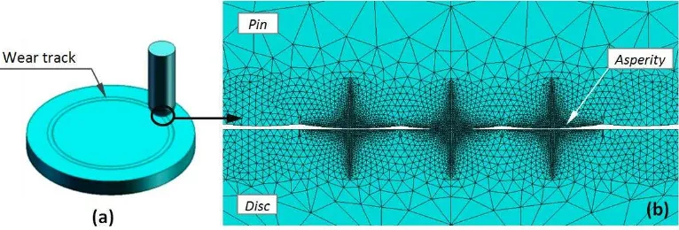
In the pin-on-disc system a hemispherical rough pin is sliding against a smooth disc, as depicted in Fig. 1. The wear simulation is performed with the commercial package ABAQUS. The simulation does not aim to si ulate the e ti e slidi g p o ess of o ta t s ste ut i stead t eats the p o le of slidi g ea as uasi -stati to sa e the o putatio al e pe se. I the odel of Hegadekatte et al. [25] a pin with radius Rp 0.794
mm is used having asperities with the certain radius. The operational conditions and some properties are given in Table 1 and are similar with [25] except for the radius of the asperities and distance between the asperities.
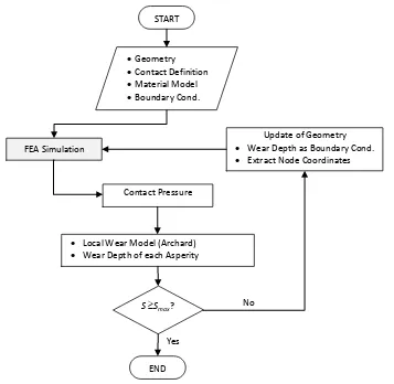
In the present model the radius of the asperities (Ras) is 50 and 25 m. The inputs for the simulation, see
the flowchart of Fig. 2, are geometry, material model, contact definition and boundary conditions. The first step of this simulation is determining the contact pressure.
Figure 2. Flowchart wear simulation.
Table 1.Operational conditions and some material properties
Description Dimension
Material of pin and disc Silicon Nitride (Si3N4)
Radius of pin (Rp) 0.794 mm Radius of asperities (Ras) 50 m and 25 m
Distance between asperities 1(for 50 m) and 0.7(for 25 m)
Poisso s atio) 0.24
Contact load (Fn) 200mN
Wear rate (kD) 13.5E-9 mm3/Nmm
You g s Modulus E) 304 GPa
The local wear depth is computed from a combination of the finite element calculated contact pressure and A ha d s ea odel:
(2)
In which, ∆hw is the wear depth, kD the wear rate, p(x,y) the contact pressure distribution and ∆s the
incremental sliding distance. The wear of the disc is not taken into account. After this step, the geometry of the
START
Update of Geometry Wear Depth as Boundary Cond. Extract Node Coordinates
Contact Pressure
Local Wear Model (Archard) Wear Depth of each Asperity
S Smax?
FEA Simulation
END Geometry Contact Definition Material Model Boundary Cond.
Yes
contact system is updated. This is repeated until the set sliding distance is met. For a more detailed FEA process to predict wear in a tribo-system, the reader is referred to [26].
The finite element model was solved using the memory of 4 GB of a personal computer and the computation time was about 15 minutes for a single simulation. Both pin and disc consists of 84159 elements. The element of A4-node linear tetrahedron was selected for this purpose. From Fig. 1b, it is clear that a refined mesh is used in the contact area and outside the contact a coarse grid is used to minimize the computational time.
3. Results and Discussion
The calculated contact area and stresses are shown in Fig. 3. The asperity at the center of the contact is loaded more than the asperities located further away from the center, this due the geometrical setting of the asperities on a curved body. In case of a conformal contact the loading of the asperities is uniform.
Fig. 3. (a) Real contact area of pin surface on asperity level Ras 50 m
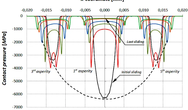
(b) pressure distribution for the initial contact at the 3rd, 1st, 5th asperity.
The contact pressure distribution on asperity level is presented in Fig. 4. From this figure it becomes clear that as wear increases with the sliding distance the real contact area increases. Further, the pressure distribution across an asperity changes significantly from an initial Hertzian pressure distribution to a pressure distribution showing at the edge of each worn asperity a pressure rise. Due to wear of the asperities located at the center of the macroscopic contact more and more surrounding asperities are involved in carrying the load.
The computed wear of the asperities is presented in Fig. 5. As expected the wear of the asperity at the center of contact area is higher than the surrounding asperities. Due to the symmetric artificial rough surface wear of the 2nd, 3rd, 4th, and 5th asperity is the same (see Fig. 5). At the start of the sliding process, the wear, reduction of the asperity height, is high (initial phase) and then tends to stabilize (final phase). In the terms of mechanical systems, the initial and the final phases are called running-in and steady-state respectively [27].
Figure 5. Wear depth of the asperities of the silicon nitride (Si3N4) pin as a function of the sliding distance.
Figure 6. (a) Average contact pressure and (b) surface roughness as a function of the sliding distance.
From Fig. 6, it can be concluded that both the average contact pressure as well as the surface roughness (Ra) at
the initial phase of the sliding process is high and then tend to stabilize in final phase, due to the conformal shape of the asperities.
4. Conclusions
In this paper, a model in wear prediction of a rough surface sliding contact has been presented. A hemispherical pin, made of silicon nitride Si3N4 with an artificial rough surface represented by uniform
distributed spherical asperities is in contact with a smooth flat disc. Both the pin and disc have similar mechanical properties. It can be concluded that the wear of the asperity at the center of the contact of the rough surface is higher than the surrounding asperities. The proposed model, FE i o i atio ith A ha d s wear law, has proven to be a powerful tool in predicting wear of rough surfaces. Future studies will be
conducted on the running-in of components in mechanical systems like MEMS in which artificial surfaces are applied to enhance the tribological performance.
Acknowledgment
The authors would like to express gratitude to the Ministry of Education and Culture of the Republic of Indonesia through the Directorate General of Higher Education for the scholarship.
References
[1] Seireg AA. 1998. Friction and lubrication in mechanical design. Marcel Dekker, New York.
[2] Greenwood JA, Williamson JBP. 1966. Contact of Nominally Flat Surfaces. Proc. R. Soc. Lond., A295 : 300-319
[3] Whitehouse DJ, Archard JF. 1970. The Properties of Random Surfaces of Significance in Their Contact. Proc. R. Soc. Lond., A316 : 97-121
[4] Greenwood JA, Trip JH. 1971. The Contact of Two Nominally Flat Rough Surfaces. Proc. Inst. Mech. Eng., 185 : 625-633 [5] Onions RA, Archard JF. 1973. The Contact of Surface Having a Random Structure. Journal Physics. D: App. Physics, 6 :
289-304
[6] Nayak PR. 1971. Random Process Model of Rough Surfaces. Journal of Lubrication Technology, 93 : 398-407 [7] McCool JI. 1986. Comparison of Models for the Contact of Rough Surfaces. Wear, 107 : 37-60
[8] Hertz H. 1882. Ueber die Beruehrung fester elastischer Koerper. J. Reine Angew. Math., 92 : 156-171 [9] Holm R. 1938. The Friction Force over the Real Area of Contact. Wiss. Veroff. Siemens-Werk, 17 : 38-42 [10] Archard JF.1953. Contact and Rubbing of Flat Surfaces. J. Appl. Phys., 24 : 981-988
[11] Popov VL. 2010. Contact Mechanics and Friction. Springer, Berlin.
[12] Tian X, Bhushan B.1996. A Numerical Three-dimensional Model for the Contact of Rough Surfaces by Variational Principle. ASME Journal of Tribology, 118 : 33-42
[13] Ren N, Lee SC. 1993. Contact Simulation of Three-dimensional Rough Surfaces Using Moving Grid Method. ASME Journal of Tribology, 116 : 597-607
[14] Lubrecht AA, Ioannides E. 1999. A Fast Solution of the Dry Contact Problem and Associated Subsurface Stress Field Using Multilevel Technique. ASME Journal of Tribology, 113 : 128-133
[15] West MA, Sayles RS. 1987. A 3-dimensional Method of Studying 3-body Contact Geometry and Stress on Real Rough Surface. Proc. 14th Leeds-Lyon Symposium on Tribology- Tribology Series, 12 : 195-200
[16] Podra P. 1997. FE Wear Simulation of Sliding Contacts. PhD thesis. Royal Institute of Technology (KTH), Stockholm. [17] Flodin A, Andersson S. 1997. Simulation of Mild Wear in Spur Gears. Wear, 207 : 16-23
[18] Podra P, Andersson S. 1999. Simulating Sliding Wear with Finite Element Method. Tribology International, 32 : 71-81 [19] Olofsson U, Andersson S, Bjorklund S. 2000. Simulation of Mild Wear in Boundary Lubricated Spherical Roller Thrust
Bearings. Wear, 241 : 180-185
[20] Flodin A, Andersson S. 2000. Simulation of Mild Wear in Helical Gears. Wear, 241: 123-128
[21] Oqvist M. 2001. Numerical Simulations of Mild Wear Using Updated Geometry with Different Step Size Approaches. Wear, 249 : 6-11
[22] Hegadekatte V. 2006. Modeling and Simulation of Dry Sliding Wear for Micro-machine Applications. PhD thesis. University of Karlsruhe, Karlsruhe.
[23] Hegadekatte V, Huber N, Kraft O. 2006. Finite Element Based Simulation of Dry Sliding Wear.Tribology Letters, 24 : 51-60
[24] Hegadekatte V, Kurzenhauser S, Huber N, Kraft O. 2008. A Predictive Modeling Scheme for Wear in Tribometers. Tribology International, 41 : 1020-1031
[25] Hegadekatte V, Hilgert J, Kraft O, Huber N. 2010. Multi Time Scale Simulations for Wear Prediction in Micro-gears. Wear, 268 : 316-324
[26] Ismail R, Tauviqirrahman M, Syafa'at I, Jamari J, Schipper DJ. 2010. The Application of Updating Geometry Model in Finite Element Analysis for Predicting the Running-in Wear on Sliding Contact, 8th ASEAN ANSYS Conference 2010, Singapore.