An Analysis-Driven Rapid Design Process for Cyber-Physical Systems
By Zsolt Lattmann
Dissertation
Submitted to the Faculty of the Graduate School of Vanderbilt University
in partial fulfillment of the requirements for the degree of
DOCTOR OF PHILOSOPHY in
Electrical Engineering August, 2016 Nashville, Tennessee
Approved:
Gábor Karsai, Ph.D.
Theodore Bapty, Ph.D.
Gautam Biswas, Ph.D.
Xenofon Koutsoukos, Ph.D.
Sandeep Neema, Ph.D.
János Sztipanovits, Ph.D.
Copyright c 2016 by Zsolt Lattmann All Rights Reserved
ACKNOWLEDGMENTS
First and foremost I wish to thank my advisor, Prof. Gábor Karsai, for his scientific advice and knowledge and many insightful discussions and suggestions. He helped me to formulate the thesis topic and guided me over almost four years of development. His questions were always the most difficult ones, and they guided me towards research challenges, answers, and solutions. He helped me learn how to clearly and precisely communicate my ideas.
He is the person who reads every single word on a page, even the fine print, and asks questions about every figure and diagram. His thorough work advocates excellence and the highest quality work based on all available information and time constraints. He clearly had a positive influence on my personality and professional career. He taught me how to effectively manage my time and be more productive; as a result, over the years at Vanderbilt University I have rarely missed deadlines, or even requested a deadline extension. I appreciate all his contributions of time, ideas, and funding to make my Ph.D. experience productive and stimulating. I am also thankful for the excellent example he has provided as a successful mentor, scientist, and professor.
I would like to thank James Klingler for helping me with his proofreading and continuous feedback on technical content and suggesting how to rephrase and reorganize certain portions of this thesis to make it easier to read and understand. Even when I was losing my motivation he encouraged me to improve the quality this document. As I learn more and more about writing, I realize how much I do not know. I truly believe that James has just started me on a journey to improving my writing skills even further. Thank you, James.
My thesis committee has given me exceptional input through all these years. Thank you to Prof. János Sztipanovits, Prof. Xenofon Koutsoukos, Prof. Gautam Biswas, Prof.
Sandeep Neema, and Prof. Ted Bapty. I would like to thank all of my committee members for their valuable feedback, which has greatly improved the quality and clarity of this thesis and helped me define the scope of this research. Prof. Sandeep Neema and Prof. Ted Bapty provided me with the opportunity to be a contributor to the Defense Advanced Research Projects Agency (DARPA) Adaptive Vehicle Make (AVM) program and several projects including the META project. They have supported several students and researchers to achieve the goals of the META project. Our META group got extremely valuable feedback from our collaborators and beta testers about the ideas implemented in the OpenMETA tools.
The members of the META group have contributed immensely to my personal and pro- fessional time at Vanderbilt University. This group has been a source of friendships as well as good advice and collaboration. The work presented in this thesis is a work of the META
group and several other teams. In particular, I would like to thank: Adam Nagel for his help with the design of the dynamics portion of the integration language Cyber-Physical Modeling Language (CyPhyML) and component specification; Patrik Meijer for his help in redesigning and reimplementing certain pieces of the OpenMETA tools and make it a more robust tool in general; Kevin Smyth for all the pair programming, debugging difficult problems, and sharing his programming experience; and the entire META development team.
Lastly, I would like to thank my family for all their love and encouragement. For my parents who raised me with a love of science and technology. I am grateful for all the support they gave me over the past decades. They always helped me to make my decisions which I greatly appreciate. Thank you.
TABLE OF CONTENTS
Page
ACKNOWLEDGMENTS . . . iii
LIST OF TABLES . . . viii
LIST OF FIGURES . . . ix
LIST OF ABBREVIATIONS . . . xi
Chapter I. Introduction . . . 1
Challenges . . . 1
Problem Description . . . 2
Thesis Goals . . . 3
Thesis Outline . . . 3
II. Background . . . 4
Cyber-Physical Systems . . . 5
Existing Design Processes . . . 6
Layered Design . . . 6
Component-Based Design . . . 6
V-model . . . 7
Model-Based Development . . . 8
Virtual integration . . . 9
Platform-Based Design . . . 9
Contract-Based Design . . . 10
Summary . . . 11
Evaluation . . . 12
Model-Based Systems Engineering . . . 12
Domain-Specific Languages . . . 14
Unified Modeling Language . . . 14
Systems Modeling Language. . . 15
Evaluation . . . 16
Model Interfaces and Composition . . . 17
Bond Graphs . . . 17
Modelica . . . 19
Evaluation . . . 21
Requirements . . . 22
Requirement and design trade-offs . . . 24
Simulation-Driven Design . . . 25
Multidisciplinary Design Analysis and Optimization . . . 27
Lessons learned . . . 28
III. High-level Design Flow . . . 30
Model Integration Platform . . . 31
Tool Integration Platform . . . 32
Execution Integration Platform . . . 33
Visualization Integration Platform . . . 34
IV. Heterogeneous component models . . . 36
Problem Statement . . . 36
Challenges . . . 37
Component and design models . . . 37
Solution . . . 37
Evaluation . . . 40
Example for model integration . . . 41
Solution . . . 42
Evaluation . . . 46
V. Analysis templates and model execution framework . . . 48
Problem Statement . . . 48
Challenges . . . 48
Solution . . . 49
Analysis template models . . . 49
Parametric exploration models . . . 50
Tool integration and analysis package execution . . . 52
Project artifacts and analysis result management . . . 53
Evaluation . . . 54
VI. Analysis-driven Rapid Design Process . . . 55
Problem Statement . . . 55
Challenges . . . 55
Solution . . . 55
Evaluation . . . 57
Oscillator . . . 58
Ground vehicle driveline . . . 72
Potential Other Applications . . . 80
VII. Conclusion . . . 82
Lessons learned . . . 82
Results . . . 83
Open research challenges. . . 84
Appendix A. Relevant publications. . . 85
Heterogeneous component models . . . 85
Analysis templates and model execution framework . . . 86
Analysis-driven Rapid Design Process . . . 86
B. Other publications . . . 88
C. Simulation error log for oscillator design . . . 89
D. Design space results for Oscillator . . . 90
REFERENCES . . . 93
LIST OF TABLES
Table Page
1. Bond graph variables for physical domains . . . 18
2. Oscillator: Requirements . . . 61
3. Oscillator: Resistor alternatives . . . 61
4. Oscillator: Capacitor alternatives . . . 61
5. Oscillator: Transistor parameters . . . 62
6. Oscillator: Transistor alternatives [33] . . . 62
7. Oscillator: Scoring weights . . . 66
8. Oscillator: Design time . . . 72
9. Vehicle driveline: Engine alternatives (23/25) [83] . . . 75
10. Vehicle driveline: Transmission alternatives (6/8) [83] . . . 76
11. Vehicle driveline: Requirements for design problem [83] . . . 80
LIST OF FIGURES
Figure Page
1. V-model [133] . . . 7
2. Platform-Based Design’s general framework [75] . . . 9
3. SysML taxonomy diagram . . . 15
4. Example Modelica model . . . 21
5. ModelicaML for SysML taxonomy diagram. . . 23
6. Workflow and integration platforms for the design process . . . 31
7. Component class diagram . . . 38
8. CyPhy Component model and existing external models . . . 38
9. AVM Component Model for Caterpillar C9 Diesel Engine [105] . . . 39
10. Design space class diagram . . . 40
11. Schematic diagram of a simple electro-mechanical system [84]. . . 42
12. Composition diagram and simulation results [84] . . . 43
13. Component model using Bond Graph or Modelica [84] . . . 44
14. Analysis template class diagram . . . 50
15. Parametric exploration class diagram . . . 51
16. Tool integration class diagram . . . 52
17. Project data structure class diagram . . . 53
18. Analysis-driven Rapid Design Process: design flow . . . 56
19. Oscillator example: Modelica.Electrical.Spice3.Examples.Oscillator [6] . . . 58
20. Oscillator example: simulation results . . . 59
21. Oscillator: Analysis template . . . 64
22. Oscillator: Design space . . . 65
23. Oscillator: Parallel axis plot colored by ranking . . . 66
24. Oscillator: Parallel axis plot colored by requirements . . . 67
25. Oscillator: Probabilistic Certificate of Correctness model . . . 68
26. Oscillator: Failed Probabilistic Certificate of Correctness configurations . . . 68
27. Oscillator: Probabilistic Certificate of Correctness (PCC) results for cfg39, cfg72, cfg3, and cfg45 . . . 69
28. Oscillator: Overlaid simulation results . . . 69
29. Oscillator: Design of Experiment model . . . 70
30. Oscillator: Design of Experiment results for rise time (cfg39 and cfg45) . . . 70
31. Vehicle driveline: Full Speed Forward Test Bench [83] . . . 74
32. Vehicle driveline: Physical limit violations [83] . . . 77
33. Vehicle driveline: Parametric Design Space Exploration Models [83] . . . 78
34. Vehicle driveline: Results of Parametric Exploration over a discrete design space [83] . . . 79
LIST OF ABBREVIATIONS
AADL Architecture Analysis and Design Language 8
ARDP Analysis-driven Rapid Design Process 3, 55–58, 60, 71–73, 77, 80, 82–85 AVM Adaptive Vehicle Make iii, 1, 2, 32, 33, 39, 43, 82
BPMN Business Process Modeling Notation 22 CAD Computer-Aided Design 26, 32, 33, 39, 50 CBD Contract-Based Design 10–12, 17
CFD Computational Fluid Dynamics 33, 50
CPS Cyber-Physical System 1–3, 5, 12, 17, 21, 28, 38, 41, 48, 51, 55, 57, 80–83 CyPhyML Cyber-Physical Modeling Language iv, 30, 37–39, 43, 44, 46, 82 DAE Differential Algebraic Equation 20
DARPA Defense Advanced Research Projects Agency iii, 1, 82 DASSL differential/algebraic system solver 59
DBD Dysfunctional Behavior Database 27 DC direct current 20
DESERT Design Space Exploration and Refinement Tool 40, 64, 65 DoE Design of Experiment 32, 51, 60, 67, 70, 71, 78, 81
DSL Domain-Specific Language 14
DSML Domain-Specific Modeling Language 43 eCar electric car 25, 26
ECU Engine Control Unit 6
EPA US Environmental Protection Agency 22 EPS Electric Power System 58
FEA Finite Element Analysis 26–28, 33, 39, 49, 50, 57 FMEA Failure Modes and Effects Analysis 27
GME Generic Modeling Environment 43 GPL General-Purpose Language 14 HBGL Hybrid Bond Graph Language 44 KCL Kirchhoff’s Current Law 20
LOC Lines-Of-Code 5
MBD Model-Based Development 8, 10, 25
MBSE Model-Based Systems Engineering 3, 5, 12, 13, 16, 21, 24, 25, 28, 30, 36, 37, 53, 56 MCS Monte Carlo Simulation 52
MDAO Multidisciplinary Design Analysis and Optimization 3, 27, 28, 33–35 MoC Model of Computation 4
ModelicaML Modelica Modeling Language 22, 23 MPP Most Probable Point Method 52
MSL Modelica Standard Library 20, 58, 71 OCL Object Constraint Language 40 ODE Ordinary Differential Equation 18, 47 OMG Object Management Group 14 OS Operating System 6
PBD Platform-Based Design 9–11, 16, 20
PCC Probabilistic Certificate of Correctness 32, 51, 52, 60, 67–69, 71, 77, 78, 81 PCE Polynomial Chaos Expansion 52
QoS Quality of Service 14
RML Requirements Modeling Language 24
SCAP Sequential Causality Assignment Propagation 18 SCR Software Cost Reduction 23
SD System Dynamics 57
SDD Simulation-Driven Design 3, 25, 27 SoC system-on-chip 10, 14
SPD Sequenced Parametric Diagram 26
SysML Systems Modeling Language 8, 14–16, 22–28 TGG Triple Graph Grammar 26
TOPSIS Technique for Order of Preference by Similarity to Ideal Solution 35, 65 TS Taylor Series Approximation 52
UBML Uniform Behavior Modeling Language 26, 28 UDR Univariate Dimension Reduction Method 52 UI User Interface 22
UML Unified Modeling Language 8, 14, 15, 22, 37, 39, 49, 50, 53 XMI XML Metadata Interchange 15
XML Extensible Markup Language 15
CHAPTER I
INTRODUCTION
Product design has become increasingly complex in recent decades. Several design meth- ods and processes have been developed to reduce the design complexity to a manageable level. These methods and approaches include: layered design, component-based design, the v-model, model-based development, virtual integration, platform-based design, and contract- based design. Model-based systems engineering leverages these methods to manage de- sign complexity and to reduce development time and costs. In contrast to the traditional document-centric design process, model-based design approaches maintain traceability and dependency among artifacts in the form of relationships between models. The building blocks of a model-based engineering tool are models that represent the requirements, system components, and subsystems. Using model-based systems engineering tools has become an accepted practice in the industry.
Challenges
Most of these design methods and processes were primarily developed for either software or hardware development. However, in Cyber-Physical Systems, computational elements are tightly integrated with physical processes and physical components. Computational elements often interact with the physical system through a distributed network [87, 88, 131]. Physical systems are acausal systems, which means that they do not have predefined inputs and outputs by nature. For a specific operating mode of the system, inputs and outputs can be derived, but it is a cumbersome process for a large complex system. One challenge is how to effectively co-design physical and software components.
Customer expectations for product cycles are getting shorter [91]. Large software com- panies create software releases continuously [116]; sometimes more than one new release is published within a day. In software development, software releases and deployment are highly automated and often follow an iterative design process with continuous integration systems that run automated tests. By decreasing the design cycle time and thereby increas- ing the number of design iterations within a given period of time, designers can be more confident that any potential problems will be discovered. The design process for complex Cyber-Physical Systems (CPSs) has not reached such a fast pace yet. In 2010, the Defense Advanced Research Projects Agency (DARPA) initiated the Adaptive Vehicle Make (AVM)
program to develop a fully integrated design process for complex CPSs [44]. The overall goal of the AVM program was to speed up the development time by 5x for complex CPSs.
Designing complex CPSs involves a large number of discipline-specific models and analysis tools. Miscommunication between models and analysis tools has negative impacts on the development time and cost. Therefore, design processes for CPSs must be orchestrated in a modeling environment where this communication is captured from the early stages of the design process to the manufacturing of the system.
There are hundreds of distinct tools used in the automotive and aerospace industry to analyze different aspects of a complex system design. These tools include both in-house, i.e., internally developed and maintained, (70%) and commercial off-the-self tools (30%), which shows that there is no single tool that can deal with all aspects of a complex design problem [146]. An adequate model of Cyber-Physical Systems must: (1) capture domain interactions (e.g., electrical power and mechanical systems), (2) incorporate multiple aspects and domain models for each component, (3) support a wide variety of analysis techniques, (4) enable the reuse of existing models from libraries, and (5) extract sufficient information from model libraries to support architecture exploration for product families.
Problem Description
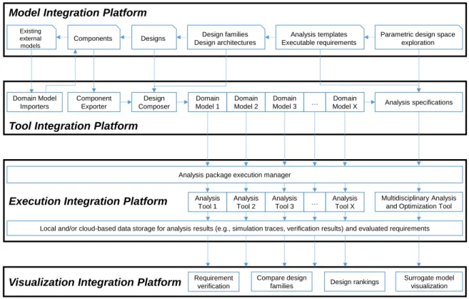
Consider the modeling of CPSs with heterogeneous component models and their interac- tions: each component model may consist of several domain-specific models that are related to each other. There are many relationships between those domain-specific models including physical or parametric relationships. Our goal is to develop concepts to capture integrated domain-specific models and their relationships for CPSs in a Model Integration Platform. When the domain-specific models are composed, a Tool Integration Platform will address how to operate domain-specific tools to facilitate domain-specific analyses driven by the com- posed domain-specific models. Usually, there is a large number of domain-specific analyses involved in a complex CPSs design problem. The required time to perform each execution can vary anywhere between a few seconds to several hours depending on the tool and the models. The challenge is further compounded when these analyses must be performed for multiple design variations or in an optimization loop. An Execution Integration Platform will address how to arrange large-scale analysis of models by the parallel execution of all independent analyses. Because the analysis can take several hours, even using parallel exe- cution, aVisualization Integration Platform will address how to collect and visualize partial datasets as individual analyses are completed, before the full result set is available. We will develop a design process that presents how to use these four platforms to reduce overall design time.
Thesis Goals
We will contribute to three platforms to improve efficiency and quality of a design process focusing on high-level design of CPSs: a Model Integration Platform, a Tool Integration Platform, and an Execution Integration Platform. The Model Integration Platform will (a) use heterogeneous component models, (b) keep the multi-domain models consistent, (c) track model dependencies, and (d) facilitate importing models from existing libraries. The Tool Integration Platform will accommodate a variety of analysis tools with flexibility to add new tools in the future. The Execution Integration Platform will provide an analysis tool independent framework for analysis execution and organization of analysis results. In addition to these platform contributions, we will prototype an analysis-driven rapid iterative design process as part of this research.
Thesis Outline
This thesis is organized as follows: Chapter II gives an overview on Cyber-Physical Sys- tems (CPSs), existing design processes, Model-Based Systems Engineering (MBSE), model interfaces and composition, requirement specification, Simulation-Driven Design (SDD), and Multidisciplinary Design Analysis and Optimization (MDAO); finally, it concludes with the lessons learned. In Chapter III the high-level design flow is presented along with four integra- tion platforms: (a) the Model Integration Platform, (b) the Tool Integration Platform, (c) the Execution Integration Platform, and (d) the Visualization Integration Platform. Chap- ter IV discusses heterogeneous component models in detail. Chapter V presents the analysis templates and model execution framework. Chapter VI shows how the above-described con- cepts enable an Analysis-driven Rapid Design Process (ARDP) that was utilized on two use cases: (a) an oscillator design and (b) a ground vehicle driveline design. Finally, Chapter VII concludes this thesis.
CHAPTER II
BACKGROUND
In this chapter we present a summary of all relevant background information related to the scope of our research. A few key concepts are defined below that are used in this chapter:
Component is a design entity that represents a physical object, a hardware piece, or a software piece. Each component has interfaces that are used to communicate with other components and the environment.
Abstraction is an information reduction and conceptualization process with a set of as- sumptions for a software component, a hardware component, or a physical component.
Model views and model aspects consider a model with multiple interdependent repre- sentations of the same software component, hardware component, or physical compo- nent.
Heterogeneous models are models using (i) different modeling aspects, e.g., computa- tional, behavioral, and structural; or (ii) different modeling domains, e.g., electrical, mechanical, etc.; or (iii) different Model of Computation (MoC), e.g., continuous time, discrete event, etc.
Multi-domain models are models that capture multiple physical domains and their in- teractions for the same component, e.g., an electrical component generates heat or an electrical component is temperature dependent.
Design is a collection of many interconnected components.
Design space is a collection of design alternatives or family of designs, where the alterna- tives differ from each other either in architecture or in design parameters.
Discrete design space considers only design alternatives from a design space where there is an architecture difference, or for a given architecture, alternative component options are available for substitution.
Parametric design space often assumes a fixed architecture choice and considers contin- uous parameter variations of components, subsystems, or both.
Virtual integration is a process in which models are composed and evaluated to predict the expected output of the system.
Cyber-Physical Systems (CPSs)
Cyber-Physical Systems (CPSs) are complex multi-domain systems that include highly interconnected and interdependent computational and physical components. CPSs orches- trate networked computational resources with physical systems [87, 88, 89, 131, 147]. Exam- ples for CPSs are: avionics, transportation air traffic control, automotive, building systems, telecommunication systems, military systems (e.g., satellites), power generation and distribu- tion, and factory automation. In CPSs there are several challenges to be solved which involve scheduling problems, capturing software and hardware interactions, representing physical in- teractions, and solving control problems.
For instance, in the power generation and distribution domain, one challenge is how to couple and operate green energy and continuous energy sources in the same network. Green energy is usually available based on a state of the environment, e.g., direct sunlight to solar panels, or wind rotating wind turbines. Another challenge is that the power demand is increasing and decreasing based on the time of the day, but the produced green energy is often not stored, therefore, it must be consumed.
Another example is the automotive domain: a premium car today contains at least 80 computers including: Engine Control Unit, Transmission Control Unit, Automatic Braking System, Air Conditioning system, entertainment system, navigation system, etc. All com- puters are connected to the car’s system bus; currently, the controller area network (CAN) bus is the standard (in the near future the standard will be FlexRay). There are around 100 million Lines-Of-Code (LOC) for such a car.
These systems often contain multiple domains and their interactions such as electro- mechanical or electro-hydraulics. Physical interactions are replaced by software interactions, which are more flexible, but it is harder to understand and model them. Physical systems are increasingly segregated by software components, e.g., fly-by-wire systems in avionics. This trend increases the demand on Model-Based Systems Engineering to succeed with providing comprehensive and complete tool sets and design processes that are capable of representing and analyzing complex CPSs.
Existing Design Processes
Layered Design
A design process using layered design defines abstraction levels for software products [91].
Every abstraction level is associated with different design activities. These abstraction levels help to decompose and compartmentalize a complex design problem into smaller units. The layered design process can have many abstraction levels, which are called layers. A lower- level layer does not belong to a higher-level layer, rather it is used by the higher-lever layer.
As a result, a layered design has a compound relationship of the uses form instead of the part of form between layers. By defining multiple layers for an application domain problem, the various design concerns are separated. Each layer is built on top of another layer. A lower-level layer encapsulates design concerns and implementations and hides them from the higher-level layers. This layered design approach was adapted for various application domains including automobile and avionic domains.
For example, in the automobile domain the AUTOSAR [9] standard was developed to define several abstraction layers: the Microcontroller Abstraction Layer, the Engine Control Unit (ECU) and Complex Drivers Layer, the Services Layer, and the Application Layer. The software components implemented in the Application Layer communicate directly with the Operating System (OS) and Services Layer; whereas the lowest level, the Microcontroller Abstraction Layer, encapsulates the actual microcontroller implementation. In the avionics domain, similar abstraction layers are defined by the ARINC standards [5].
One of the challenges in layered design is to define a set of abstraction layers for a domain problem which provide sufficient information and encapsulation for the higher-level layers, while the number of implementation options remains broad.
Component-Based Design
In component-based design, designs are composed of multiple design entities called com- ponents [38]. Each component has a set of interfaces that are used in the composition, where each component interface may be connected to one or many other component interfaces.
Components encapsulate the implementation, which makes them highly reusable through- out the design process. Having components defined can significantly accelerate the design process, because the components can be developed and implemented in parallel. Defin- ing components on different levels of the design containment is called hierarchical system decomposition; this reduces the complexity of the design problem [121].
Figure 1: V-model [133]
There are two major challenges with component-based design: (a) how to specify compo- nent interfaces to be rich enough to cover all phases of the entire design process and (b) how to capture a family of designs with various alternative component and architecture options possibly representing product variations and product families.
V-model
The V-model is a product development process primarily developed for software applica- tions. Originally, the V-model was published in 1997 in the Development Standards for IT Systems of the Federal Republic of Germany document [41]. The V-Model became a stan- dard for all civil and military federal agencies in Germany. The objectives of the V-Model are: minimization of project risks, improvement and guarantee of quality, reduction of total cost, and improvement of communication between stakeholders. Since the initial develop- ment of the standard, the V-model was adapted for other application domains including aircraft design and software design. The V-model is named after its V-shape diagram, as shown in Figure 1, which splits the development process into two major phases: (a) a design phase and (b) an integration phase. [49]
The design phase starts with the analysis of the product-level requirements, which is fol- lowed by the development of a functional architecture diagram. The functional architecture diagram is divided into individual domains such as mechanical, electrical, digital hardware, software, etc. After the individual domain-specific components and subsystems are designed and tested, they are integrated at the subsystem level followed by the system-level integration across multiple domains according to the logical architecture diagram. Product integration,
validation, and product certification against product level requirements are the final steps in the integration phase of the V-model.
The V-model reaches its limitations as systems become more and more complex, in particular when they involve several domains along with cross-domain interactions and in- terdependencies. Because the domains are kept in separate models and there are no direct linkages between the different domain representations, the subsystem- and system-level in- tegrations are tedious. After the system is physically integrated, it may fail to meet product level requirements. Such failures are identified too late in the design process, and they ne- cessitate model updates or in a worst case scenario in a complete redesign of the system. All the aforementioned shortcomings of the V-model inject costly unpredictable delays in the entire product development process.
Model-Based Development
In Model-Based Development (MBD), models are used to capture and organize informa- tion for products to be designed [122, 139]. A collection of models is a full representation of a system design. Models and their relationships are explicit representations of traceability and dependency of design artifacts. The MBD design process captures requirements from the early stages of the design activity in the form of models. It is a common practice in MBD to use code generation tools to facilitate virtual integration and to automate portions of the subsystem- and system-level integration as well as verify the design against the specified design requirements. The MBD design process inspired system engineers to create different modeling languages such as the Architecture Analysis and Design Language (AADL) [46]
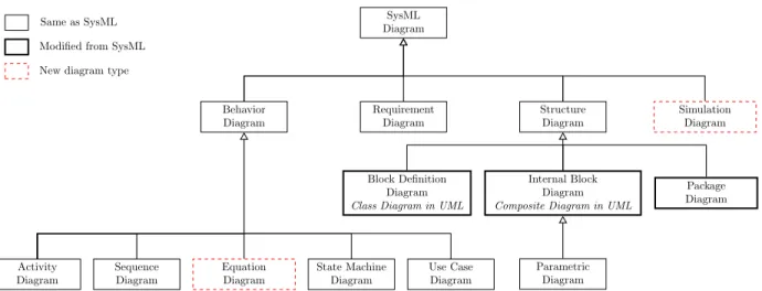
for performance critical system design, the Unified Modeling Language (UML) is a general purpose modeling language for the software engineering field, and the Systems Modeling Language (SysML) for system-level modeling.
Using system-level modeling languages does not solve the entire product design problem.
Therefore, application and domain-specific tools must be used in conjunction with system- and architecture-level modeling languages and tools. Tool-specific models are developed for different aspects (views). For instance, MATLAB-Simulink [96] is often used for controller and control-flow modeling; 20-Sim [1], Bond Graphs [74], MATLAB-SimScape [94], Catia [143], and Modelica [7] are used for physical system modeling. Automatic code generation for simulation and behavior analysis is possible, which helps to verify the design against the requirements and validate the models against empirical data.
The drawback to having tool-specific models is that it increases the risk of inconsistency between different aspects (views) of the same design entity.
Figure 2: Platform-Based Design’s general framework [75]
Virtual integration
Historically, systems integration (e.g., V-model integration phase) is a challenging task because after the system prototype is physically integrated and realized, it still may fail to meet system requirements. Virtual integration addresses this challenge by composing models of components and subsystems, resulting in a fully-composed system model. We can then perform analyses on this virtual prototype to verify the predicted behavior of the system.
Virtual integration minimizes the risk in the integration phase of the V-model, because the designed subsystems can be virtually composed and analyzed at the system level according to the system architecture diagram. As a result, this process reduces the number of physical prototypes required to test the system.
As we discussed before, a complex system design often involves several domains including multiple physical domains such as electrical, hydraulic, one- and multi-dimensional mechan- ical, and thermal. Therefore, the modeling tools should support heterogeneous component models and modeling their interactions. For instance, Ptolemy [24] addressed heterogeneous component modeling and composition with different semantics. Modelica [7] and SimScape supports physical modeling and simulation at an advanced level including multi-body dy- namics and hardware-in-the-loop simulations.
Platform-Based Design
Platform-Based Design (PBD) is an integration-oriented design approach for developing complex products based upon a software or a hardware platform [10, 75]. The software or hardware platform provides a platform-specific abstraction layer for the designers to develop platform-specific applications. A common semantic domain, often called the system platform,
is presented in the middle of Figure 2 [75]. The application space is mapped to the system platform by a top-down refinement process and the architecture space is exported to the system platform by a bottom-up exposure.
PBD emphasizes the reuse of platform-specific components and is intended to reduce development costs, risks, and time by using virtual integration [10]. It incorporates the advantages of four design methods: (1) Component-Based Design, (2) virtual integration, (3) layered design, and (4) Model-Based Development. By combining these four design methods, PBD reduces the design complexity by hierarchical system decomposition and definitions of platform-specific abstraction layers. In addition to the decomposition techniques, PBD also supports multi-layer optimization through multiple viewpoints, whereas other design processes do not. The PBD concepts have been successfully applied in several different domains including: automotive, building automation, printers, wireless networks, network processors, system-on-chip (SoC) and electronic design. One key difference between the layered design process and PBD is that layered design predefines the abstraction layers for any design problem within the domain, but PBD leaves the abstraction layer definitions to the particular application or design platform.
Each design platform consists of three key elements: (a) a component library, (b) models of components, and (c) connectivity and composition rules between components. The models of components may be mathematical models at different levels of abstraction or placeholders to indicate customization. By adding platform-specific constraints to the composition of components, a family of designs is represented which satisfy those constraints. A platform instance is called an architecture, which is defined by the composition of platform compo- nents. An architecture captures how the system does what it is supposed to do and fulfills all platform-specific constraints.
Contract-Based Design
Contract-Based Design (CBD) augments Platform-Based Design withcontracts, where a contract is defined for each component with a set ofassumptions andpromises[22, 133]. The assumptions are definedonly for ports that are controlled by the environment. The promises are defined only for ports that are controlled by the component. There are two types of contracts: horizontal and vertical. Horizontal contracts are defined among subsystems on the same level of abstraction, and are used for virtual integration testing. Vertical contracts are used across design layers, when each component can be further refined or decomposed in the design process.
Assumptions are frequently categorized into strong and weak assumptions. Examples for strong assumptions are: meeting a standard or being part of vertical contracts for com- position. Violation of vertical contracts means incompatibility across design layers in the decomposition hierarchy. Weak assumptions are desired properties of the system such as cost, manufacturing lead time, etc. When a design becomes invalid and fails to meet the contracts, it is possible to backtrack the contract assertion to the higher-level contracts by maintaining dependency between contracts. In such cases, weak assumptions can be relaxed (e.g. rebudgeting) to fulfill all contracts.
CBD augments PBD with contracts; these contracts assist with determining whether the architecture composition is valid or not. CBD considers only component choices from the component library that result in legal composition during architecture exploration.
Summary
In this section we presented existing design processes and methods. The goals of each design method are to reduce design complexity and development time. Design complexity is reduced by defining abstraction layers or decomposing the design problem based on contain- ment. Development time is often reduced by using components or models as design entities.
Components and models represent the designed product with an explicit representation of traceability and dependency of the design artifacts. These components and models are highly reusable in the design, even across multiple subsystems. Components and models can be virtually integrated using composition which reduces the number of physical prototypes that must be built and tested.
When the design product is based on a specific platform, a platform-specific abstraction is provided for the designers to build their platform-specific components and products. The platform can be either a software platform, a hardware platform, or both. The platform- specific components and the platform itself can have a set of assumptions and promises.
The set of assumptions and promises for a given component is a contract. Contract-Based Design defines the types and the composition of contracts. Contracts can be used to verify the correctness of the virtual integration. If there is an assertion on a system-level contract, it is possible to trace back to a lower-level component in the hierarchy that caused the assertion.
Evaluation
The design processes outlined above were mainly developed for software design, where models and components have inputs and outputs. This means that the direction of infor- mation flow between components (i.e., causality) is explicitly defined in the system by the designers.
In complex Cyber-Physical System design, components often span multiple domains in- cluding behavioral, structural, and computational. This requires a design process that ac- commodates multiple views of component models. The different views are often dependent on each other. The design process must support acausal (i.e., bidirectional) interfaces. De- pending on the operation mode of the system, the inputs and outputs may change. Consider a hybrid car: when the car accelerates the batteries provide electrical energy to the mechan- ical system; when the car applies the brakes the mechanical system charges the batteries.
In Contract-Based Design the promises are defined only for ports that are controlled by the environment; this design approach is not directly applicable for physical system modeling where the inputs and the outputs can change. For CBD to be applicable, each operation mode of the system must first be elaborated. Unfortunately, elaborating all operation modes of complex CPSs results in a large combinatorial space, which is difficult to manage and simultaneously increases model complexity. One of the goals of many design processes is to reduce complexity.
The aforementioned design methods give no or minimal support for architecture and parametric design space exploration which highly limits designers in finding the optimal solution for their problem. It is important that any evaluation method used in the design process (e.g., evaluation of contract assertions) can also be applied in parametric design space exploration (e.g., in a design optimization).
Model-Based Systems Engineering
Model-Based Systems Engineering (MBSE) is a systems engineering methodology that captures views and analyses for a product design at the system level. The system-level views are the collection of virtually integrated models that represent the integrated system [47, 139, 141].
In traditional engineering design, several documents are developed: requirement docu- ments, conceptual design documents, detailed design documents, etc. Unfortunately, there is an inherent dependency across all aforementioned documents. In this document-centric approach, the documents are the primary artifacts in the design process. The relationships between such documents are often poorly maintained. However, MBSE organizes the doc- uments and their dependencies by associating them to models. These models become the
primary artifacts in the design process and are stored in a model database. The models refer to each other explicitly and the relationship between models yields the relationships between documents. When a document is changed it results in a model change. By this model change all relevant linked models and other documents can be identified and updated.
The goal of Model-Based Systems Engineering is to improve efficiency and quality of the design process and semantic interoperability. However, several obstacles remain in achieving that goal [120].
Obstacles to improving efficiency
Manually developing models is labor intensive and expensive. MBSE tools should leverage and accommodate pre-existing models and model libraries. Complex design problems often involve the usage of several heterogeneous model libraries and analysis tools. Setup of analyses is time-consuming and cumbersome due to the lack of the interoperability of the models. Having heterogeneous analysis tools implies having heterogeneous models, which leads to multiple views (aspects, concerns) of the same model. Manually maintaining the dependencies between model views of the same system is error-prone. Even if the models are stored in a centralized place, there are recurring activities, e.g., writing design reports, which can negatively impact the efficiency unless some or full automation is provided by the MBSE tools.
Obstacles to improving quality
The different models and model views must be kept synchronized with each other to ensure model consistency. Assume that a model has at least two views: a behavioral and a structural view. Some of the model parameters are shared between the different views.
Changing such interdependent parameter values must result in a change in both analysis- specific behavioral and structural models.
Many MBSE tools provide hierarchical modeling, which aids to group information and knowledge that people can easily process in every level of the hierarchy. In complex system designs, multiple teams are involved in the entire design process, where each team may include several people. Hierarchical modeling improves and clarifies communication between people and teams. Different people and design teams have different objectives, beliefs, and preferences which form the basis of their design decisions. Those divergent design decisions may lead to irrational designs.
Domain-Specific Languages (DSLs)
A General-Purpose Language (GPL) is usually a general purpose programming language which is applicable in a wide variety of application domains. This is in contrast to Domain- Specific Languages (DSLs), which are specifically built for a given domain and provide domain-specific abstraction through the use of terms and concepts from a specific domain [150, 51]. Oftentimes, several custom tools are developed in conjunction with the DSL.
Generally, these tools are called interpreters that act on the domain-specific models, and generators (i.e., compilers) that translate the domain-specific models into source code or another model representation.
Each DSL consists of one or more concrete syntax definitions and one abstract syntax definition. The concrete syntax is used to visualize, manage, and edit domain-specific models;
it can be graphical, textual, tabular, or a mix of those. The abstract syntax of a DSL is defined in a meta-model, which enforces the static or structural semantics of the domain.
The meta-model contains type definitions, composition rules, and constraints. However, the execution or behavioral semantics of a DSL are defined and realized by an execution engine.
Different partitions of the DSL can have different behavioral semantics and could require multiple execution engines to realize them. DSLs are developed for a variety of engineers, and not just software engineers, depending on the application domain [150].
Unified Modeling Language (UML)
The Unified Modeling Language (UML) is a graphical modeling language developed by the Object Management Group (OMG) [50, 98, 115]. UML is used to model software ap- plication structure, behavior, and architecture. Different application domains may require more specific concepts than what UML specifies. UML profiles are extensions to UML that define stereotypes using domain-specific concepts; these stereotypes can be used to build domain-specific models. UML profiles have been developed and maintained for commonly used application domains. For example, a few domain- or application-specific profiles are:
UML Profile for Software Radio, UML Profile for Modeling Quality of Service (QoS) and Fault Tolerance Characteristics and Mechanisms, UML Profile for system-on-chip (SoC), and UML Testing Profile. The first version of the UML Profile for Systems Engineering (SysML) was developed by systems engineers in 2005, who aimed to model systems engineering ap- plications including physical and computational parts.
SysML Diagram
Requirement Diagram Behavior
Diagram
Sequence Diagram Activity
Diagram
State Machine Diagram
Use Case Diagram
Structure Diagram
Internal Block Diagram Composite Diagram in UML Block Definition
Diagram Class Diagram in UML
Package Diagram
Parametric Diagram Same as UML 2
Modified from UML 2 New diagram type
Figure 3: SysML taxonomy diagram
Systems Modeling Language (SysML)
The Systems Modeling Language (SysML) is a general purpose graphical modeling lan- guage for systems engineering applications [52, 141, 152]. SysML extends and modifies a subset of the UML 2.0 as shown in Figure 3. The UML Activity Diagram contains some extensions and restrictions in the SysML profile. TheBlock Definition Diagram is similar to the UML Class Diagram and the Internal Block Diagram is similar to the UML Composite Structure Diagram; both have some extensions and restrictions as described in the SysML specification [114].
The new diagram types (i.e., extensions) are: theRequirement Diagram and theParamet- ric Diagram. Each SysML and UML model can be serialized into XML Metadata Interchange (XMI) format for model exchange between different SysML or UML tools, respectively.
The block definition diagram and the internal block diagram provide support for nested and typed ports. The nested and typed ports enable reusable blocks and clearly defined interfaces for composition. SysML defines two kinds of ports: one that exposes its own features called full ports and another one that exposes ports or features of its parent called proxy ports. Another modification is the support of flow properties in block diagrams. The flow properties can define the kind of items that flow through the ports, for instance: data, material, or energy. Each block can define a set of flow properties that are associated with ports. Definition of flow properties for ports is essential for physical system modeling and developing interconnectable components. In older versions of SysML (before version 1.3), flow ports served the same purpose; the newer versions of the SysML specification describe how to migrate the old models, because the flow ports are marked as deprecated elements.
SysML supports text-based requirements modeling and organization using requirement diagrams. The requirement diagram supports hierarchical decomposition or grouping of the
requirements. Each requirement may specify a function or a performance goal that the system must perform or achieve, respectively. The requirement block can be related to other blocks and elements in the SysML model using the copy, derived, satisfy, verify,refine, and trace relationships.
The parametric diagram is a specialization of the internal block diagram. Each parametric diagram may contain one or more constraint properties and their parameters. In addition to the internal block diagram restrictions, all properties must be bound to either a constraint parameter or contain a property that is bound to one. Internal block diagrams are similar to the placeholders in the PBD. A parametric block diagram with constraints and bound property values is similar to a platform instance in the Platform-Based Design.
Several extensions have been developed for SysML including a collaborative web-based SysML editor with limited authoring capabilities [21]. Other SysML-based tools and exten- sions are described in detail in the Simulation-Driven Design section.
Evaluation
Domain-Specific Languages provide strong type checking for model composition using domain-specific concepts and terms. SysML provides a general-purpose Model-Based Sys- tems Engineering modeling language with built-in model traceability and dependency, but it lacks structural semantics and domain-specific concepts. Domain-specific concepts can be added to SysML by defining SysML profiles. Many application domains have been developed as SysML profiles because the SysML specification [114] does not define any semantics for general SysML models. However, when a SysML profile is used and connections or objects are created the structural semantics are not strictly enforced at the time of modeling. Con- sider a SysML profile defined for a domain which contains mechanical and electrical port types. A designer is allowed to connect a mechanical port to an electrical port, but that connection makes the entire model invalid, because the model cannot be physically realized.
Such modeling errors might be revealed too late in the design process which could increase the design time and costs.
Model-Based Systems Engineering tools must support: (a) importing existing multi- domain component libraries for each aspect of the component including physical behavior, structural, and computational; (b) strong type checking for composition (i.e., structural semantics) which makes the models correct by construction; (c) seamless integration with existing analysis tools for automated analysis execution; and (d) iterative model develop- ment.
Model Interfaces and Composition
Models interact with other models or the environment through model interfaces. Models are composed into larger entities by connecting one or more model interfaces together. The interfaces are used to exchange data, material, or energy between components or to establish a structural relationship between components [42]. Strongly-typed interfaces improve model clarity and eliminate composition mistakes, e.g., connecting a data interface to an energy flow interface. The interfaces can be divided into two main categories: causal and acausal.
Causal interfaces define the direction of information flow through the interfaces; hence, they are either inputs or outputs. When causal interfaces are composed, there are strict rules describing how inputs and outputs can be connected. Acausal interfaces do not predefine the direction of the energy flow; the direction is usually determined by the composition or the operating mode of the system. If the operating mode changes during the analysis of the system, the inputs and outputs might need to be changed for certain interfaces.
In Contract-Based Design, contracts are associated with component models, where each contract is given as a set of promises and assumptions defined on input and output in- terfaces, respectively. If the environment fulfills the specified assumptions, then the model promises certain properties or behavior. The assumption/promise approach is also called the assume/guarantee, or assumption/commitment approach. This paradigm has been applied in a number of approaches including software specification, system specification, and logical proofs of system-level properties. These component-based contract specifications have been generalized to architectural contracts for discrete event systems and state machines [22].
It is important to note that both discrete event systems and state machines have causal interfaces.
Contract specifications can be used for CPSs as presented in [133, 112]. In CPSs, con- tracts are always specified in the computational blocks or they are defined on the boundary of the physical system. The physical system model interacts with computational blocks through causal interfaces using sensors and actuators. Contracts are never specified on acausal interfaces inside a physical system model or between physical component models.
Physical system models require acausal interfaces for efficient modeling and design. Sev- eral modeling languages support acausal or equation-based modeling such as Bond Graphs [74], Modelica [7, 53, 149], and SimScape Language [95].
Bond Graphs
The Bond Graph notation is a graphical modeling language for physical systems based on power and energy flow. The Bond Graph elements are domain independent, which aims to bridge the communication gap between different domain experts. In other words, if a
mechanical engineer and an electrical engineer are both familiar with Bond Graphs, they can model electro-mechanical systems including mechanical systems or electrical circuits, respectively. When they share the models with each other, both of them can interpret the behavior of entire system including cross-domain interactions. This property of Bond Graphs provides reusability and cross-domain interoperability.
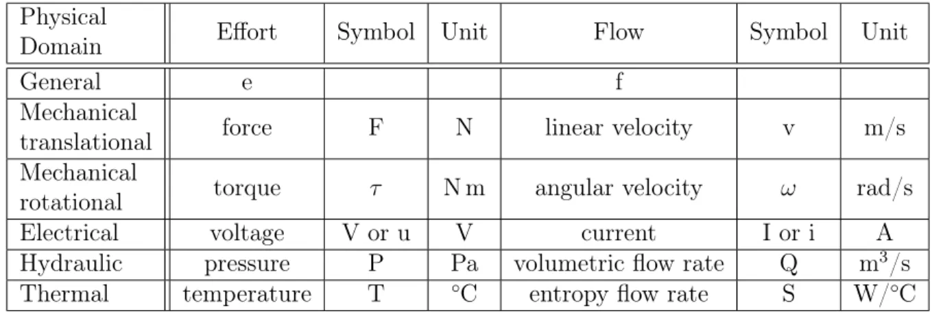
Basic Bond Graphs contain three kinds of elements: one-port elements, two-port ele- ments, and multi-port elements called junctions. The ports of the elements are connected together and the connections are called bonds and are represented with a half-arrow. The direction of the half-arrow denotes the assumed positive direction of the power flow between the adjacent elements. Each bond represents aneffort and aflow variable, which are domain dependent as shown in Table 1. The product of the effort and flow variables is power, which corresponds to the energy flow between the adjacent elements.
Physical
Domain Effort Symbol Unit Flow Symbol Unit
General e f
Mechanical
translational force F N linear velocity v m/s
Mechanical
rotational torque τ N m angular velocity ω rad/s
Electrical voltage V or u V current I or i A
Hydraulic pressure P Pa volumetric flow rate Q m3/s
Thermal temperature T ◦C entropy flow rate S W/◦C
Table 1: Bond graph variables for physical domains
Even though the bonds are directional, Bond Graph is an acausal modeling paradigm, which means that there are no dedicated input and output variables in the system. Inputs and outputs depend on the graph and the composition of the elements. Causality is assigned to each bond based on a given set of rules for each element using the Sequential Causality Assignment Propagation (SCAP) algorithm [74]. Every valid Bond Graph can be directly translated into a set of Ordinary Differential Equations (ODEs) after the causality is assigned.
The acausal modeling eliminates the need of rewriting the ODEs if the system topology changes, because the new set of ODEs can be automatically derived based on the new system’s topology.
Bond Graphs are often used to model existing system dynamics to better understand, track, trace, and analyze fault propagation in physical systems [20, 45, 101, 102]. Bond Graphs are also frequently used for modeling and simulation of mechatronic systems [18].
The Bond Graph methodology [19] was augmented with multi-bond graphs to facilitate the
modeling of complex multi-body dynamics [30]. In addition to the modeling and simulation of the mechatronic systems, the control of mechatronic systems is presented in [74].
Bond Graphs do not support hierarchical modeling, which can lead into diagrams with hundreds of elements and connections on the same diagram for a large scale complex system.
Even though Bond Graph supports acausal models, it is challenging to compose Bond Graphs with other acausal (or equation-based) modeling languages such as Modelica. Designers like to reuse the existing model libraries even if they are built within a different modeling language. Basic Bond Graph modeling evolved to model complex multi-body dynamics [30], but complexity of the diagrams significantly increases, which reduces productivity and efficiency. To overcome the increasing model complexity, a Bond Graph library was developed for Modelica [29]. The Bond Graph library leverages the hierarchical decomposition feature of Modelica to manage design complexity at different levels of the hierarchy.
Bond Graphs have been applied to other domains. For example, the Modelica Bond Graph library is used to create the system dynamics model of a servo-positioning system;
the power flow information is used to monitor the effectiveness of a control system [97]. The method compares the efficiency of controllers with different topologies, where one controller is a linear controller and the other one uses a non-linear anti-backlash element. A Modelica based simulation tool, Dymola, is used to generate the simulation results, which allows us to compare the efficiency of the two controllers in a quantitative way by using an energy-based control evaluation method. This approach helps control engineers to quantify the quality of a particular control design and compare different designs.
Modelica
Modelica is an equation-based unified object-oriented modeling language for systems modeling defined by the Modelica Language Specification [7]. The Modelica language is domain independent, but domain-specific libraries and concepts have been developed [53, 149]. In fact, a Modelica Standard Library is provided, which is built on the Modelica language, and provides domain-specific ports and elements for several physical domains such as electrical, mechanical rotational, mechanical translational, fluid, magnetic, thermal, etc.
In Modelica everything is a class, and there are specialized classes which pose additional restrictions on the containment or the structure of the class. A few commonly used and important class types: type, record, connector, model, block, function, and package.
The type is used to specialize variables by restricting the causality (input or output), the size (e.g., 1-dimensional or 3-dimensional), and the unit (e.g., acceleration in m/s). The record is used to group multiple type definitions. For instance, different fluid types have different values for density, dynamic viscosity, kinematic viscosity, conductivity, etc. If all of
those properties are grouped into arecord it is easy to create several fluid type specifications like water, air, or carbon dioxide by providing the expected values.
The connector class type defines pairs of potential and flow variables as acausal ports.
The flow variables are marked with a keyword called flow, whereas the potential variables are not marked explicitly. For instance, in the electrical domain the potential variable is the voltage and the flow variable is the current. This is similar to the Bond Graphs as discussed in the previous section. Connectors are connected with the connect statement. When the Modelica code is translated to a set of Differential Algebraic Equations (DAEs) the connect statements are resolved into multiple equations. For instance, in the electrical domain the set of connected connectors will be resolved to and obey Kirchhoff’s Current Law (KCL).
The model and block are structurally similar except the block classes cannot contain any connectors (i.e., acausal interfaces). The function class cannot have any connectors and equations, it can only have inputs, outputs, parameters, and algorithms. All of the aforementioned elements can be organized into packages.
Modelica supports abstract classes by using thepartial keyword and inheritance by using the extend keyword. Each class can be marked as partial, which means the class itself cannot be instantiated, because it does not contain the full definition yet. Each class can be extended (or derived) from another class that has at least the same class restrictions. For instance, a model can be extended from a block, but a block cannot be extended from a model. In addition to abstract classes and inheritance, templates and constraining classes on templates are also supported. The replaceable keyword identifies placeholders in the model similar to the placeholders in Platform-Based Design, where each placeholder can be constrained by an other class. When the placeholder is replaced with a class, that class must be the constraining class or any of its subtype.
Even though Modelica is a textual language and the Modelica code is stored as a text file with a .mo file extension, the Modelica Specification allows to store graphical information including locations and icons as annotations as well as tool-specific annotations. Modelica is a language and there are existing Modelica tools that can interpret the Modelica code and execute Modelica simulation models. The Modelica tools often contain a graphical editor and always contain at least one DAE solver. There are open-source Modelica simulation environments such as JModelica.org [100], and OpenModelica [117]. There are commercial Modelica simulation environments such as Dymola [144], MapleSim [93], Wolfram System- Modeler [154], SimulationX [70], and CyModelica [35].
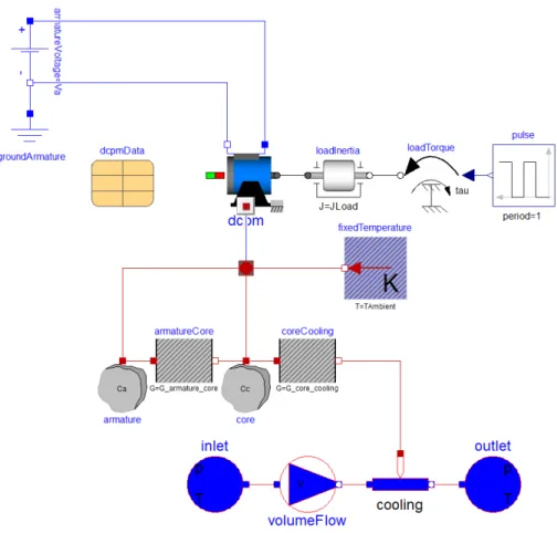
Figure 4 depicts a Modelica model from the Modelica Standard Library (MSL) called Modelica.Electrical.Machines.Examples.DCMachines.DCPM_Cooling. The system con- tains a direct current (DC) motor with a cooling system, where the mechanical load of the
Figure 4: Example Modelica model
motor is pulse modulated. Even this simple system contains four different physical domains:
electrical, mechanical rotational, thermal, and fluid. Each domain can be easily identified in the diagram, because the connectors are strongly typed and have different visual representa- tions in each domain. These diagrams help to increase productivity and model clarity, and result in minimizing miscommunication between subject matter experts.
Evaluation
Strongly-typed causal and acausal interfaces are essential parts of Model-Based Systems Engineering for Cyber-Physical System design. They assist the designers with developing models that are correct by construction. For example, in Modelica it is not possible to connect an electrical pin to a mechanical flange (such a connection would result in compile time error and some editors prohibit such a connection in the graphical user interface).
Another example is the fluid port connections: two fluid ports can be connected because they are structurally compatible, but the Modelica compiler also checks if the defined medium type
matches on each connected port. This means that the system model will not be interpreted and simulated unless it is semantically correct.
Having well-defined domain-specific interfaces helps with building model libraries around partial (i.e., placeholder) models, which define the interface of a specific component while leaving the implementation undefined. These placeholders make architecture and design space exploration easier. The component placeholders can be easily substituted with any compatible component. With this flexibility, highly reusable and extensible component li- braries, component interfaces, and architecture templates can be developed.
Requirements
Requirements are expected properties of the system and they are typically testable [126, 140]. There are two main categories of requirements: (a) functional requirements and (b) non-functional requirements. Functional requirements describe specific behavior or functionality of the system, i.e., what the system should do. Examples for functional require- ments are: the system must minimize injuries upon collision or the system must transport people and objects from A to B. Non-functional requirements describe the desired opera- tions of the system, i.e., how the system works or operates. Examples for non-functional requirements are: the safety system must be deployed when a collision is detected or the fuel consumption must be greater than 30 MPG over the highway US Environmental Protection Agency (EPA) drive cycle profile.
Several tools have been developed to model requirements such as Blueprint [17], Enter- prise Architect [90], HP Quality Center [119], IBM Rational DOORS [64], IBM Rational DOORS Next Generation [65], Jira [8], PTC Integrity [129], Mingle [155], etc. The require- ments management tools allow designers to store and retrieve design requirements written in a textual form as well as relate requirements to each other or group multiple requirements together. Some of these requirement management tools are coupled with requirement devel- opment, project management, (automated) testing, User Interface (UI) mockup, or visual modeling capabilities. Visual modeling is often provided as graphical models such as UML, Business Process Modeling Notation (BPMN) [113], or SysML models.
SysML provides a first class concept to support requirements in the form of requirement diagrams as presented in the previous section. Even though requirements are organized in models and several relationships can be established between the model entities, the require- ments are still stored as textual artifacts without any execution semantics. To evaluate the requirements, execution semantics must be defined for the models or specific diagram types.
For instance, the Modelica Modeling Language (ModelicaML) [127] extends SysML with two new diagram types and modifies three existing SysML diagram types. These extensions
SysML Diagram
Requirement Diagram Behavior
Diagram
Equation Diagram Sequence
Diagram Activity
Diagram
State Machine Diagram
Use Case Diagram
Structure Diagram
Internal Block Diagram Composite Diagram in UML Block Definition
Diagram Class Diagram in UML
Package Diagram
Parametric Diagram
Simulation Diagram Same as SysML
Modified from SysML New diagram type
Figure 5: ModelicaML for SysML taxonomy diagram
and modifications facilitate the execution and evaluation of requirements for physical sys- tems. Figure 5 depicts the ModelicaML taxonomy that includes the equation diagram and the simulation diagram in addition to the SysML taxonomy.
Modelica supports object-oriented equation-based modeling of system designs. However, the Modelica language itself lacks first class requirement support, thus ModelicaML was de- veloped as a profile for SysML. ModelicaML augments SysML with an equation diagram that contains Modelica equations, which represent the model behavior, therefore it is a subclass of the behavior diagram. The simulation diagram defines an experiment for a referenced Mod- elica model including parameters for the included Modelica model, and storing simulation results calledsimResults for plotting and requirement evaluation. One or more requirements can be referenced from the simulation diagram, which are linked to the simulation results through the satisfy relationship.
Formal notation of requirements is used along with automated tools to produce high- quality requirement specifications. One formal notation of requirements is called Software Cost Reduction (SCR) [59], which was developed to concisely and unambiguously specify software requirements for real-time embedded systems. The SCR method uses tables to cap- ture, relate, and organize design requirements that can be used to define design requirement specifications. If requirements are defined using formal notation (e.g., SCR) then require- ment analysis can be performed including automated consistency checking of requirement specifications [58]. The automated consistency checker is used to check the specification in an application-independent way for reachability, coverage, syntax, and type correctness. The formal requirement specification is executed symbolically to verify that it represents design- ers or customers intent. An SCR* toolset for specifying requirements was developed [57]
and applied in developing high assurance avionics systems [16]. Other research describes the
benefits of formal Requirements Modeling Language (RML): develop and present require- ments as models using object-centered representation and reasoning with models through consistency checking or simulation [55].
Requirement and design trade-offs
When a set of requirements is defined, there is often more than one potential design which fulfills all design requirements. In such cases, design trade-off studies are performed to compare the different design alternatives with respect to the design requirements. Design trade-off studies appear during multiple phases in the design process including: (a) during the conceptual design phase and (b) during the detailed design phase. In the conceptual design phase, there are design trade-off studies between different architectures, which require minimal computational resources compared to detailed analysis, because most of the time surrogate models are used for each architecture option. In traditional design processes often a single architecture is selected, which eliminates all other architecture options. Then the selected architecture is fully developed to a detailed design. Detailed designs are subject to further design trade-off studies by changing design parameters or features and evaluating robustness properties of the system. Regardless of the parameter variations, the architecture remains intact at this phase of the design process.
MBSE tools can be used to model design alternatives and variations of products. A SysML-based design chain information modeling technique is presented in [157] for variety management in production reconfiguration. They consider a switchgear enclosure produc- tion process: a SysML model is developed to perform structural, behavior, constraint, and requirements analysis for reconfiguration of the process. The generic design structure con- tains: (1) product structure, (2) variety feature, and (3) configuration constraint. A product structure represents a single architecture choice, which is shared by all variants from a prod- uct family. The variety features include color, material, and thickness of the switchgear enclosure. The configuration constraint specifies a set of rules that must be held by the final product. One example is the material compatibility: the material of the top, bottom, and vertical brackets must be the same. Another example is the color compatibility: the color of the top, bottom, and vertical brackets must be the same. Even though variety is allowed in the product family, all design requirements and configuration constraints must be met by any design configuration.
If developing or virtual prototyping of multiple design alternatives is unreasonable, for instance due to cost or time, then certain key decisions must be made in advance. Designers need to make decisions regarding technologies, architectures, design solutions, or products to use based on the functional and non-functional design requirements. A method for analyzing
![Figure 1: V-model [133]](https://thumb-ap.123doks.com/thumbv2/123dok/10733199.0/20.918.237.685.111.379/figure-1-v-model-133.webp)
![Figure 2: Platform-Based Design’s general framework [75]](https://thumb-ap.123doks.com/thumbv2/123dok/10733199.0/22.918.283.634.104.383/figure-2-platform-based-design-general-framework-75.webp)


![Figure 9: AVM Component Model for Caterpillar C9 Diesel Engine [105]](https://thumb-ap.123doks.com/thumbv2/123dok/10733199.0/52.918.202.710.125.472/figure-avm-component-model-caterpillar-c9-diesel-engine.webp)
![Figure 12: Composition diagram and simulation results [84]](https://thumb-ap.123doks.com/thumbv2/123dok/10733199.0/56.918.117.807.111.263/figure-12-composition-diagram-and-simulation-results-84.webp)