i
IC Engines
Fourth Edition
About the Author
V. GANESAN currently working as Professor Emeritus in the Department of Mechanical Engineering, Indian Institute of Technology Madras, is the recipient of Anna University National Award for Outstanding Academic for the Year 1997. He was the Head of the Department of Mechanical Engineering, at Indian Institute of Technology Madras between October 2000 and June 2002. He was also the Dean (Academic Research) at Indian Institute of Technology Madras between January 1998 and October 2000.
He has so far published more than 350 research papers in national and international journals and conferences and has guided 20 M.S. and 40 Ph.D.s.
Among other awards received by him are the Babcock Power Award for the best fundamental scientific paper of Journal of Energy (1987), the Institution of Engineers Merit Prize and Citation (1993), SVRCET Surat Prize (1995), Sri Rajendra Nath Mookerjee Memorial Medal (1996), Automobile Engineer of the Year by the Institution of Automobile Engineers (India) (2001), Institution of Engineers (India), Tamil Nadu Scientist Award (TANSA) – 2003 by Tamil Nadu State Council for Science and Technology, ISTE Periyar Award for Best Engineering College Teacher (2004), N K Iyengar Memorial Prize (2004) by Institution of Engineers (India), SVRCET Surat Prize (2004), Khosla National Award (2004), Bharat Jyoti Award (2006), UWA Outstanding Intellectuals of the 21st Century Award by United Writers Association, Chennai (2006), 2006 SAE Cliff Garrett Turbomachinery Engineering Award by SAE International, USA, Sir Rajendra Nath Mookerjee Memorial Prize (2006) by Institution of Engineers, Environmental Engineering Design Award 2006 by The Institution of Engineers (India), 2006 SAE Cliff Garrett Turbomachinery Engineering Award (2007), Excellence in Engineering Education (Triple “E”) Award by SAE International, USA (2007), Rashtriya Gaurav Award in the field of Science and Technology by India International Friendship Society (2012), and Best Citizens of India Award by International Publishing House New Delhi (2012). He is the Fellow of Indian National Academy of Engineering, National Environmental Science Academy, Fellow of SAE International, USA, and Institution of Engineers (India). He has also been felicitated by International Combustion Institute Indian Section for lifetime contribution in the field of I C engines and combustion.
Dr. Ganesan has authored several other books on Gas Turbines, Computer Simulation of Four- Stroke Spark-Ignition Engines and Computer Simulation of Four-Stroke Compression-Ignition Engines and has also edited several proceedings. He was formerly the Chairman of Combustion Institute (Indian Section) and is currently the Chairman of Engineering Education Board of SAE (India), besides being a member of many other professional societies.
Dr. Ganesan is actively engaged in a number of sponsored research projects and is a consultant for various industries and R&D organizations.
iii
Tata McGraw Hill Education Private Limited
New Delhi McGraw-Hill Offices
New Delhi New York St louis San Francisco Auckland Bogotá Caracas Kuala lumpur lisbon london Madrid Mexico City Milan Montreal
San Juan Santiago Singapore Sydney Tokyo Toronto V Ganesan
Professor Emeritus
Department of Mechanical Engineering Indian Institute of Technology Madras
Chennai
IC Engines
Fourth Edition
Published by the Tata McGraw Hill Education Private Limited, 7 West Patel Nagar, New Delhi 110 008.
IC Engines
Copyright © 2012, by Tata McGraw Hill Education Private Limited.
No part of this publication may be reproduced or distributed in any form or by any means, electronic, mechanical, photocopying, recording, or otherwise or stored in a database or retrieval system without the prior written permission of the publishers. The program listings (if any) may be entered, stored and executed in a computer system, but they may not be reproduced for publication.
This edition can be exported from India only by the publishers, Tata McGraw Hill Education Private Limited.
ISBN (13): 978-1-25-900619-7 ISBN (10): 1-25-900619-0
Vice President and Managing Director—MHE: Ajay Shukla Head—Higher Education Publishing and Marketing: Vibha Mahajan Publishing Manager—SEM & Tech Ed.: Shalini Jha
Sr Editorial Researcher: Harsha Singh
Executive—Editorial Services: Sohini Mukherjee Sr Production Manager: Satinder Singh Baveja Production Executive: Anuj K Shriwastava
Marketing Manager—Higher Education: Vijay Sarathi Sr Product Specialist—SEM and Tech. Voc: Tina Jajoriya Graphic Designer—Cover: Meenu Raghav
General Manager—Production: Rajender P Ghansela Production Manager—Production: Reji Kumar
Information contained in this work has been obtained by Tata McGraw-Hill, from sources believed to be reliable. However, neither Tata McGraw-Hill nor its authors guarantee the accuracy or completeness of any information published herein, and neither Tata McGraw-Hill nor its authors shall be responsible for any errors, omissions, or damages arising out of use of this information. This work is published with the understanding that Tata McGraw-Hill and its authors are supplying information but are not attempting to render engineering or other professional services. If such services are required, the assistance of an appropriate professional should be sought.
Printed at Avon Printers, Plot No. 16, Main Loni Road, Jawahar Nagar, Industrial Area, Shahdara, Delhi-110094.
Cover Printer: AP Offset R
Tata McGraw-Hill
DEDICATED TO MY BELOVED MOTHER
L. SEETHA AMMAL
Focussing on the need of a first level text book for the undergraduates, post- graduates and a professional reference book for practicing engineers, the au- thor of this work Dr. V. Ganesan has brought forth this volume using his extensive teaching and research experience in the field of internal combustion engineering. It is a great pleasure to write a foreword to such a book which satisfies a long-felt requirement.
For selfish reasons alone, I wish that this book would have come out much earlier for the benefit of several teachers like me who have finished their in- nings a long time ago. For me, this would have been just the required text book for my young engineering students and engineers in the transportation and power fields. The style of the book reflects the teaching culture of pre- mier engineering institutions like IITs, since a vast topic has to be covered in a comprehensive way in a limited time. Each chapter is presented with elegant simplicity requiring no special prerequisite knowledge of supporting subjects.
Self-explanatory sketches, graphs, line schematics of processes and tables have been generously used to curtail long and wordy explanations. Numerous il- lustrated examples, exercises and problems at the end of each chapter serve as a good source material to practice the application of the basic principles presented in the text. SI system of units has been used throughout the book which is not so readily available in the currently-used books.
It is not a simple task to bring out a comprehensive book on an all- encompassing subject like internal combustion engines. Over a century has elapsed since the discovery of the diesel and gasoline engines. Excluding a few developments of rotary combustion engines, the IC engines has still retained its basic anatomy. As a descendent of the steam engine, it is still crystallized into a standard piston-in-cylinder mechanism, reciprocating first in order to rotate finally. The attendant kinematics requiring numerous moving parts are still posing dynamic problems of vibration, friction losses and mechanical noise. Empiricism has been the secret of its evolution in its yester years.
As our knowledge of engine processes has increased, these engines have con- tinued to develop on a scientific basis. The present day engines have to satisfy the strict environmental constraints and fuel economy standards in addition to meeting the competitiveness of the world market. Today, the IC engine has synthesized the basic knowledge of many disciplines — thermodynamics, fluid flow, combustion, chemical kinetics and heat transfer as applied to a system with both spatial and temporal variations in a state of non-equilibrium. With the availability of sophisticated computers, art of multi-dimensional mathe- matical modelling and electronic instrumentation have added new refinements to the engine design. From my personal knowledge, Dr. Ganesan has himself made many original contributions in these intricate areas. It is a wonder for me how he has modestly kept out these details from the text as it is beyond the scope of this book. However, the reader is not denied the benefits of these
investigations. Skillfully the overall findings and updated information have been summarized as is reflected in topics on combustion and flame propa- gation, engine heat transfer, scavenging processes and engine emissions – to name a few examples. Indeed, it must have been a difficult task to summa- rize the best of the wide ranging results of combustion engine research and compress them in an elegant simple way in this book. The author has also interacted with the curriculum development cell so that the contents of the book will cater to the needs of any standard accredited university.
I congratulate the author, Dr. V. Ganesan on bringing out this excellent book for the benefit of students in IC engines. While many a student will find it rewarding to follow this book for his class work, I also hope that it will motivate a few of them to specialize in some key areas and take up combustion engine research as a career. With great enthusiasm, I recommend this book to students and practicing engineers.
B. S. Murthy Former Professor, IIT Madras
We are bringing out the fourth edition of the book after the third edition has undergone fifteen reprints. Just to recall the history, the first edition of this book, published in 1994, had 15 Chapters which were framed in such a way that it will be useful to both academia and industry. Based on the feedback and response from the students and teachers the book was revised in 2003 with the addition of five more chapters taking into account the recent developments in engine technology and management. Again, the feedback from academia helped me to revise the book in 2007 for the second time with the addition of multiple choice questions. It is gratifying to note that all the three editions have received overwhelming response and appreciation from the students, teachers and practicing engineers.
I am extremely happy to receive the continuous positive feedback from the students and teachers. The review of the third edition by eminent reviewers has prompted me to revise the book to bring out this edition. In this, I have included a new chapter on Nonconventional Engines, which brings out the modern trends in the I C Engine development. The topics included are:
• Common Rail Direct Injection (CRDI) Engine
• Dual fuel and Multi-fuel Engine
• Free Piston Engine
• Gasoline Direct Injection (GDI) Engine
• Homogeneous charge Compression Ignition (HCCI) Engine
• Lean Burn Engine
• Stirling Engine
• Stratified Charge Engine
• Variable Compression Ratio(VCR) Engine
• Wankel Engine
I am sure that this will satisfy the long felt need of teachers, students and practicing engineers to understand the latest developments. Further, I have included the topic on vegetable oil and biodiesel in the chapter on alternate fuels which is the latest trend in engine fuel research. Additional materials, wherever appropriate, have been added in various chapters. Almost all the chapters have been thoroughly revised.
In writing this book, I have kept in mind the tremendous amount of ma- terial which the students and practicing engineers of today are expected to cover. On this count, the chapters have been organized to form a continuous
logical narrative. Maximum care has been taken to minimize the errors and typing mistakes. I would be obliged to the readers for informing me any such errors and mistakes and will be thankful for bringing them to my notice. I am grateful to all those who are supporting this book.
It would be impossible to refer in detail, to the many persons whom I have consulted in the compilation of this work. I take this opportunity to thank all those who have helped me directly or indirectly in bringing out this book. This edition would not have been brought to this perfection but for the sincere and dedicated efforts of Ms. Vijayashree, who has helped me in compiling this book. My thanks are due to the Centre for Continuing Education of IIT Madras for their support under book writing scheme.
I hope this edition will also receive the same continued overwhelming sup- port from academia and practicing engineers. I will be thankful for any con- structive criticism for improvements in the future edition of the book.
V GANESAN
Foreword vii
Preface ix
Nomenclature xxxi
1 Introduction 1
1.1 Energy Conversion 1
1.1.1 Definition of ‘Engine’ 1
1.1.2 Definition of ‘Heat Engine’ 1
1.1.3 Classification and Some Basic Details of Heat Engines 1 1.1.4 External Combustion and Internal Combustion Engines 2 1.2 Basic Engine Components and Nomenclature 3
1.2.1 Engine Components 3
1.2.2 Nomenclature 5
1.3 The Working Principle of Engines 6
1.3.1 Four-Stroke Spark-Ignition Engine 6 1.3.2 Four-Stroke Compression-Ignition Engine 8
1.3.3 Four-stroke SI and CI Engines 10
1.3.4 Two-Stroke Engine 10
1.3.5 Comparison of Four-Stroke and Two-Stroke Engines 12
1.4 Actual Engines 13
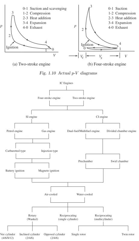
1.5 Classification of IC Engines 13
1.5.1 Cycle of Operation 16
1.5.2 Type of Fuel Used 16
1.5.3 Method of Charging 17
1.5.4 Type of Ignition 17
1.5.5 Type of Cooling 17
1.5.6 Cylinder Arrangements 17
1.6 Application of IC Engines 19
1.6.1 Two-Stroke Gasoline Engines 19
1.6.2 Two-Stroke Diesel Engines 20
1.6.3 Four-Stroke Gasoline Engines 20
1.6.4 Four-Stroke Diesel Engines 21
1.7 The First Law Analysis of Engine Cycle 21
1.8 Engine Performance Parameters 22
1.8.1 Indicated Thermal Efficiency (ηith) 22
1.8.2 Brake Thermal Efficiency (ηbth) 23
1.8.3 Mechanical Efficiency (ηm) 23
1.8.4 Volumetric Efficiency (ηv) 23
1.8.5 Relative Efficiency or Efficiency Ratio (ηrel) 24
1.8.6 Mean Effective Pressure (pm) 24
1.8.7 Mean Piston Speed (sp) 25
1.8.8 Specific Power Output (Ps) 25
1.8.9 Specific Fuel Consumption (sf c) 26
1.8.10 Inlet-Valve Mach Index (Z) 26
1.8.11 Fuel-Air (F/A) or Air-Fuel Ratio (A/F) 26
1.8.12 Calorific Value (CV) 27
1.9 Design and Performance Data 28
Worked out Examples 30
Review Questions 37
Exercise 38
Multiple Choice Questions 42
2 Air-Standard Cycles and Their Analysis 47
2.1 Introduction 47
2.2 The Carnot Cycle 48
2.3 The Stirling Cycle 50
2.4 The Ericsson Cycle 51
2.5 The Otto Cycle 52
2.5.1 Thermal Efficiency 53
2.5.2 Work Output 54
2.5.3 Mean Effective Pressure 55
2.6 The Diesel Cycle 55
2.6.1 Thermal Efficiency 56
2.6.2 Work Output 58
2.6.3 Mean Effective Pressure 58
2.7 The Dual Cycle 58
2.7.1 Thermal Efficiency 58
2.7.2 Work Output 60
2.7.3 Mean Effective Pressure 60
2.8 Comparison of the Otto, Diesel and Dual Cycles 61 2.8.1 Same Compression Ratio and Heat Addition 61 2.8.2 Same Compression Ratio and Heat Rejection 62 2.8.3 Same Peak Pressure, Peak Temperature & Heat Rejection 62 2.8.4 Same Maximum Pressure and Heat Input 63 2.8.5 Same Maximum Pressure and Work Output 64
2.9 The Lenoir Cycle 64
2.10 The Atkinson Cycle 65
2.11 The Brayton Cycle 66
Worked out Examples 68
Review Questions 97
Exercise 98
Multiple Choice Questions 103
3 Fuel–Air Cycles and their Analysis 107
3.1 Introduction 107
3.2 Fuel–Air Cycles and their Significance 107
3.3 Composition of Cylinder Gases 109
3.4 Variable Specific Heats 109
3.5 Dissociation 111
3.6 Effect of Number of Moles 113
3.7 Comparison of Air–Standard and Fuel–Air Cycles 114
3.8 Effect of Operating Variables 115
3.8.1 Compression Ratio 115
3.8.2 Fuel–Air Ratio 117
Worked out Examples 121
Review Questions 128
Exercise 128
Multiple Choice Questions 129
4 Actual Cycles and their Analysis 131
4.1 Introduction 131
4.2 Comparison of Air-Standard and Actual Cycles 131
4.3 Time Loss Factor 132
4.4 Heat Loss Factor 137
4.5 Exhaust Blowdown 137
4.5.1 Loss Due to Gas Exchange Processes 138
4.5.2 Volumetric Efficiency 139
4.6 Loss due to Rubbing Friction 142
4.7 Actual and Fuel-Air Cycles of CI Engines 142
Review Questions 143
Multiple Choice Questions 144
5 Conventional Fuels 147
5.1 Introduction 147
5.2 Fuels 147
5.2.1 Solid Fuels 147
5.2.2 Gaseous Fuels 147
5.2.3 Liquid Fuels 148
5.3 Chemical Structure of Petroleum 148
5.3.1 Paraffin Series 148
5.3.2 Olefin Series 149
5.3.3 Naphthene Series 150
5.3.4 Aromatic Series 150
5.4 Petroleum Refining Process 151
5.5 Important Qualities of Engine Fuels 153
5.5.1 SI Engine Fuels 154
5.5.2 CI Engine Fuels 156
5.6 Rating of Fuels 157
5.6.1 Rating of SI Engine Fuels 157
5.6.2 Rating of CI Engine Fuels 158
Review Questions 159
Multiple Choice Questions 160
6 Alternate Fuels 163
6.1 Introduction 163
6.2 Possible Alternatives 164
6.3 Solid Fuels 164
6.4 Liquid Fuels 166
6.4.1 Alcohol 166
6.4.2 Methanol 167
6.4.3 Ethanol 168
6.4.4 Alcohol for SI Engines 168
6.4.5 Reformulated Gasoline for SI Engine 169 6.4.6 Water-Gasoline Mixture for SI Engines 169
6.4.7 Alcohol for CI Engines 170
6.5 Surface-Ignition Alcohol CI Engine 171
6.6 Spark-Assisted Diesel 172
6.7 Vegetable Oil 172
6.8 Biodiesel 173
6.8.1 Production 174
6.8.2 Properties 175
6.8.3 Environmental Effects 175
6.8.4 Current Research 175
6.9 Gaseous Fuels 176
6.9.1 Hydrogen 176
6.10 Hydrogen Engines 177
6.10.1 Natural Gas 178
6.10.2 Advantages of Natural Gas 179
6.10.3 Disadvantages of Natural Gas 179
6.10.4 Compressed Natural Gas (CNG) 180
6.10.5 Liquefied Petroleum Gas (LPG) 180
6.10.6 Advantages and Disadvantages of LPG 181 6.10.7 Future Scenario for LPG Vehicles 183 6.10.8 LPG (Propane) Fuel Feed System 183
6.11 Dual Fuel Operation 183
6.12 Other Possible Fuels 184
6.12.1 Biogas 184
6.12.2 Producer Gas 185
6.12.3 Blast Furnace Gas 185
6.12.4 Coke Oven Gas 185
6.12.5 Benzol 185
6.12.6 Acetone 186
6.12.7 Diethyl Ether 186
Review Questions 186
Multiple Choice Questions 187
7 Carburetion 189
7.1 Introduction 189
7.2 Definition of Carburetion 189
7.3 Factors Affecting Carburetion 189
7.4 Air–Fuel Mixtures 190
7.5 Mixture Requirements at Different Loads and Speeds 190 7.6 Automotive Engine Air–Fuel Mixture Requirements 192
7.6.1 Idling Range 192
7.6.2 Cruising Range 193
7.6.3 Power Range 194
7.7 Principle of Carburetion 195
7.8 The Simple Carburetor 196
7.9 Calculation of the Air–Fuel Ratio 197
7.9.1 Air–Fuel Ratio Neglecting Compressibility of Air 200 7.9.2 Air–Fuel Ratio Provided by a Simple Carburetor 200
7.9.3 Size of the Carburetor 201
7.10 Essential Parts of a Carburetor 201
7.10.1 The Fuel Strainer 201
7.10.2 The Float Chamber 201
7.10.3 The Main Metering and Idling System 202
7.10.4 The Choke and the Throttle 204
7.11 Compensating Devices 206
7.11.1 Air-bleed jet 206
7.11.2 Compensating Jet 207
7.11.3 Emulsion Tube 207
7.11.4 Back Suction Control Mechanism 208
7.11.5 Auxiliary Valve 210
7.11.6 Auxiliary Port 210
7.12 Additional Systems in Modern Carburetors 210
7.12.1 Anti-dieseling System 211
7.12.2 Richer Coasting System 212
7.12.3 Acceleration Pump System 212
7.12.4 Economizer or Power Enrichment System 212
7.13 Types of Carburetors 213
7.13.1 Constant Choke Carburetor 214
7.13.2 Constant Vacuum Carburetor 214
7.13.3 Multiple Venturi Carburetor 214
7.13.4 Advantages of a Multiple Venturi System 216
7.13.5 Multijet Carburetors 216
7.13.6 Multi-barrel Venturi Carburetor 217
7.14 Automobile Carburetors 218
7.14.1 Solex Carburetors 218
7.14.2 Carter Carburetor 220
7.14.3 S.U. Carburetor 222
7.15 Altitude Compensation 223
7.15.1 Altitude Compensation Devices 224
Worked out Examples 225
Review Questions 234
Exercise 235
Multiple Choice Questions 238
8 Mechanical Injection Systems 241
8.1 Introduction 241
8.2 Functional Requirements of an Injection System 241
8.3 Classification of Injection Systems 242
8.3.1 Air Injection System 242
8.3.2 Solid Injection System 242
8.3.3 Individual Pump and Nozzle System 243
8.3.4 Unit Injector System 244
8.3.5 Common Rail System 244
8.3.6 Distributor System 245
8.4 Fuel Feed Pump 246
8.5 Injection Pump 246
8.5.1 Jerk Type Pump 246
8.5.2 Distributor Type Pump 248
8.6 Injection Pump Governor 248
8.7 Mechanical Governor 250
8.8 Pneumatic Governor 251
8.9 Fuel Injector 251
8.10 Nozzle 252
8.10.1 Types of Nozzle 253
8.10.2 Spray Formation 255
8.10.3 Quantity of Fuel and the Size of Nozzle Orifice 257
8.11 Injection in SI Engine 258
Worked out Examples 259
Review Questions 266
Exercise 267
Multiple Choice Questions 268
9 Electronic Injection Systems 271
9.1 Introduction 271
9.2 Why Gasoline Injection? 271
9.2.1 Types of Injection Systems 272
9.2.2 Components of Injection System 273
9.3 Electronic Fuel Injection System 275
9.3.1 Merits of EFI System 276
9.3.2 Demerits of EFI System 276
9.4 Multi-Point Fuel Injection (MPFI) System 277
9.4.1 Port Injection 277
9.4.2 Throttle Body Injection System 278
9.4.3 D-MPFI System 278
9.4.4 L-MPFI System 279
9.5 Functional Divisions of MPFI System 279
9.5.1 MPFI-Electronic Control System 279
9.5.2 MPFI-Fuel System 279
9.5.3 MPFI-Air Induction System 279
9.6 Electronic Control System 281
9.6.1 Electronic Control Unit (ECU) 281
9.6.2 Cold Start Injector 282
9.6.3 Air Valve 282
9.7 Injection Timing 283
9.8 Group Gasoline Injection System 284
9.9 Electronic Diesel Injection System 286
9.10 Electronic Diesel Injection Control 287
9.10.1 Electronically Controlled Unit Injectors 287 9.10.2 Electronically Controlled Injection Pumps (Inline and
Distributor Type) 288
9.10.3 Common-Rail Fuel Injection System 290
Review Questions 292
Multiple Choice Questions 293
10 Ignition 295
10.1 Introduction 295
10.2 Energy Requirements for Ignition 295
10.3 The Spark Energy and Duration 296
10.4 Ignition System 296
10.5 Requirements of an Ignition System 297
10.6 Battery Ignition System 297
10.6.1 Battery 298
10.6.2 Ignition Switch 299
10.6.3 Ballast Resistor 299
10.6.4 Ignition Coil 299
10.6.5 Contact Breaker 300
10.6.6 Capacitor 301
10.6.7 Distributor 301
10.6.8 Spark Plug 302
10.7 Operation of a Battery Ignition System 304
10.8 Limitations 305
10.9 Dwell Angle 306
10.10 Advantage of a 12 V Ignition System 307
10.11 Magneto Ignition System 307
10.12 Modern Ignition Systems 309
10.12.1 Transistorized Coil Ignition (TCI) System 310 10.12.2 Capacitive Discharge Ignition (CDI) System 312
10.13 Firing Order 312
10.14 Ignition Timing and Engine Parameters 314
10.14.1 Engine Speed 314
10.14.2 Mixture Strength 315
10.14.3 Part Load Operation 315
10.14.4 Type of Fuel 315
10.15 Spark Advance Mechanism 315
10.15.1 Centrifugal Advance Mechanism 316
10.15.2 Vacuum Advance Mechanism 317
10.16 Ignition Timing and Exhaust Emissions 318
Review Questions 319
Multiple Choice Questions 320
11 Combustion and Combustion Chambers 323
11.1 Introduction 323
11.2 Homogeneous Mixture 323
11.3 Heterogeneous Mixture 324
11.4 Combustion in Spark–Ignition Engines 324
11.5 Stages of Combustion in SI Engines 324
11.6 Flame Front Propagation 326
11.7 Factors Influencing the Flame Speed 327
11.8 Rate of Pressure Rise 329
11.9 Abnormal Combustion 330
11.10 The Phenomenon of Knock in SI Engines 330
11.10.1 Knock Limited Parameters 332
11.11 Effect of Engine Variables on Knock 333
11.11.1 Density Factors 333
11.11.2 Time Factors 334
11.11.3 Composition Factors 335
11.12 Combustion Chambers for SI Engines 336
11.12.1 Smooth Engine Operation 337
11.12.2 High Power Output and Thermal Efficiency 337 11.13 Combustion in Compression-Ignition Engines 339
11.14 Stages of Combustion in CI Engines 342
11.14.1 Ignition Delay Period 342
11.14.2 Period of Rapid Combustion 344
11.14.3 Period of Controlled Combustion 344
11.14.4 Period of After-Burning 344
11.15 Factors Affecting the Delay Period 344
11.15.1 Compression Ratio 345
11.15.2 Engine Speed 346
11.15.3 Output 347
11.15.4 Atomization and Duration of Injection 347
11.15.5 Injection Timing 347
11.15.6 Quality of Fuel 347
11.15.7 Intake Temperature 347
11.15.8 Intake Pressure 348
11.16 The Phenomenon of Knock in CI Engines 348 11.17 Comparison of Knock in SI and CI Engines 350
11.18 Combustion Chambers for CI Engines 352
11.18.1 Direct–Injection Chambers 353
11.18.2 Indirect–Injection Chambers 355
Review Questions 357
Multiple Choice Questions 358
12 Engine Friction and Lubrication 361
12.1 Introduction 361
12.1.1 Direct Frictional Losses 361
12.1.2 Pumping Loss 361
12.1.3 Power Loss to Drive Components to Charge
and Scavenge 362
12.1.4 Power Loss to Drive the Auxiliaries 362
12.2 Mechanical Efficiency 362
12.3 Mechanical Friction 363 12.3.1 Fluid-film or Hydrodynamic Friction 363
12.3.2 Partial-film Friction 363
12.3.3 Rolling Friction 363
12.3.4 Dry Friction 363
12.3.5 Journal Bearing Friction 364
12.3.6 Friction due to Piston Motion 364
12.4 Blowby Losses 364
12.5 Pumping Loss 365
12.5.1 Exhaust Blowdown Loss 365
12.5.2 Exhaust Stroke Loss 365
12.5.3 Intake Stroke Loss 365
12.6 Factors Affecting Mechanical Friction 366
12.6.1 Engine Design 366
12.6.2 Engine Speed 367
12.6.3 Engine Load 367
12.6.4 Cooling Water Temperature 367
12.6.5 Oil Viscosity 367
12.7 Lubrication 367
12.7.1 Function of Lubrication 368
12.7.2 Mechanism of Lubrication 368
12.7.3 Elastohydrodynamic Lubrication 371
12.7.4 Journal Bearing Lubrication 372
12.7.5 Stable Lubrication 374
12.8 Lubrication of Engine Components 375
12.8.1 Piston 375
12.8.2 Crankshaft Bearings 376
12.8.3 Crankpin Bearings 376
12.8.4 Wristpin Bearing 376
12.9 Lubrication System 377
12.9.1 Mist Lubrication System 377
12.9.2 Wet Sump Lubrication System 379
12.9.3 Dry Sump Lubrication System 382
12.10 Crankcase Ventilation 383
12.11 Properties of Lubricants 384
12.11.1 Viscosity 385
12.11.2 Flash and Fire Points 385
12.11.3 Cloud and Pour Points 385
12.11.4 Oiliness or Film Strength 386
12.11.5 Corrosiveness 386
12.11.6 Detergency 386
12.11.7 Stability 386
12.11.8 Foaming 386
12.12 SAE Rating of Lubricants 386
12.12.1 Single-grade 386
12.12.2 Multi-grade 387
12.13 Additives for Lubricants 388
12.13.1 Anti-oxidants and Anticorrosive Agents 388
12.13.2 Detergent-Dispersant 389
12.13.3 Extreme Pressure Additives 389
12.13.4 Pour Point Depressors 389
12.13.5 Viscosity Index Improvers 389
12.13.6 Oiliness and Film Strength Agents 389
12.13.7 Antifoam Agents 390
Review Questions 390
Multiple Choice Questions 390
13 Heat Rejection and Cooling 393
13.1 Introduction 393
13.2 Variation of Gas Temperature 393
13.3 Piston Temperature Distribution 394
13.4 Cylinder Temperature Distribution 395
13.5 Heat Transfer 395
13.6 Theory of Engine Heat Transfer 397
13.7 Parameters Affecting Engine Heat Transfer 399
13.7.1 Fuel-Air Ratio 399
13.7.2 Compression Ratio 399
13.7.3 Spark Advance 399
13.7.4 Preignition and Knocking 399
13.7.5 Engine Output 399
13.7.6 Cylinder Wall Temperature 400
13.8 Power Required to Cool the Engine 400
13.9 Need for Cooling System 400
13.10 Characteristics of an Efficient Cooling System 401
13.11 Types of Cooling Systems 401
13.12 Liquid Cooled Systems 401
13.12.1 Direct or Non-return System 402
13.12.2 Thermosyphon System 403
13.12.3 Forced Circulation Cooling System 403
13.12.4 Evaporative Cooling System 407
13.12.5 Pressure Cooling System 408
13.13 Air–Cooled System 409
13.13.1 Cooling Fins 409
13.13.2 Baffles 411
13.14 Comparison of Liquid and Air–Cooling Systems 411 13.14.1 Advantages of Liquid-Cooling System 411
13.14.2 Limitations 412
13.14.3 Advantages of Air-Cooling System 412
13.14.4 Limitations 412
Review Questions 413
Multiple Choice Questions 414
14 Engine Emissions and Their Control 417
14.1 Introduction 417
14.2 Air Pollution due to IC Engines 417
14.3 Emission Norms 418
14.3.1 Overview of the Emission Norms in India 419 14.4 Comparison between Bharat Stage and Euro norms 419
14.5 Engine Emissions 421
14.5.1 Exhaust Emissions 421
14.6 Hydrocarbons (HC) 422
14.7 Hydrocarbon Emission 423
14.7.1 Incomplete Combustion 423
14.7.2 Crevice Volumes and Flow in Crevices 424 14.7.3 Leakage Past the Exhaust Valve 425
14.7.4 Valve Overlap 425
14.7.5 Deposits on Walls 425
14.7.6 Oil on Combustion Chamber Walls 426 14.8 Hydrocarbon Emission from Two-Stroke Engines 426 14.9 Hydrocarbon Emission from CI Engines 427
14.10 Carbon Monoxide (CO) Emission 428
14.11 Oxides Of Nitrogen (NOx) 429
14.11.1 Photochemical Smog 430
14.12 Particulates 430
14.13 Other Emissions 433
14.13.1 Aldehydes 433
14.13.2 Sulphur 433
14.13.3 Lead 434
14.13.4 Phosphorus 435
14.14 Emission Control Methods 435
14.14.1 Thermal Converters 435
14.15 Catalytic Converters 436
14.15.1 Sulphur 439
14.15.2 Cold Start-Ups 440
14.16 CI engines 441
14.16.1 Particulate Traps 441
14.16.2 Modern Diesel Engines 442
14.17 Reducing Emissions by Chemical Methods 442
14.17.1 Ammonia Injection Systems 443
14.18 Exhaust Gas Recirculation (EGR) 443
14.19 Non-Exhaust Emissions 445
14.19.1 Evaporative Emissions 446
14.19.2 Evaporation Loss Control Device (ELCD) 447 14.20 Modern Evaporative Emission Control System 448
14.20.1 Charcoal Canister 449
14.21 Crankcase Blowby 450
14.21.1 Blowby Control 450
14.21.2 Intake Manifold Return PCV System (Open Type) 450
Review Questions 452
Multiple Choice Questions 453
15 Measurements and Testing 457
15.1 Introduction 457
15.2 Friction Power 457
15.2.1 Willan’s Line Method 458
15.2.2 Morse Test 459
15.2.3 Motoring Test 461
15.2.4 From the Measurement of Indicated and Brake Power 461
15.2.5 Retardation Test 461
15.2.6 Comparison of Various Methods 463
15.3 Indicated Power 463
15.3.1 Method using the Indicator Diagram 464
15.3.2 Engine Indicators 465
15.3.3 Electronic Indicators 465
15.4 Brake Power 467
15.4.1 Prony Brake 469
15.4.2 Rope Brake 470
15.4.3 Hydraulic Dynamometer 471
15.4.4 Eddy Current Dynamometer 471
15.4.5 Swinging Field DC Dynamometer 473
15.4.6 Fan Dynamometer 473
15.4.7 Transmission Dynamometer 474
15.4.8 Chassis Dynamometer 474
15.5 Fuel Consumption 474
15.5.1 Volumetric Type Flowmeter 475
15.5.2 Gravimetric Fuel Flow Measurement 478 15.5.3 Fuel Consumption Measurement in Vehicles 479
15.6 Air Consumption 479
15.6.1 Air Box Method 480
15.6.2 Viscous-Flow Air Meter 480
15.7 Speed 481
15.8 Exhaust and Coolant Temperature 481
15.9 Emission 482
15.9.1 Oxides of Nitrogen 482
15.9.2 Carbon Monoxide 483
15.9.3 Unburned Hydrocarbons 484
15.9.4 Aldehydes 485
15.10 Visible Emissions 487
15.10.1 Smoke 487
15.11 Noise 490
15.12 Combustion Phenomenon 491
15.12.1 Flame Temperature Measurement 491
15.12.2 Flame Propagation 494
15.12.3 Combustion Process 495
Review Questions 496
Multiple Choice Questions 497
16 Performance Parameters and Characteristics 499
16.1 Introduction 499
16.2 Engine Power 500
16.2.1 Indicated Mean Effective Pressure (pim) 500
16.2.2 Indicated Power (ip) 501
16.2.3 Brake Power (bp) 502
16.2.4 Brake Mean Effective Pressure (pbm) 504
16.3 Engine Efficiencies 505
16.3.1 Air-Standard Efficiency 505
16.3.2 Indicated and Brake Thermal Efficiencies 505
16.3.3 Mechanical Efficiency 505
16.3.4 Relative Efficiency 506
16.3.5 Volumetric Efficiency 506
16.3.6 Scavenging Efficiency 507
16.3.7 Charge Efficiency 507
16.3.8 Combustion Efficiency 507
16.4 Engine Performance Characteristics 507
16.5 Variables Affecting Performance Characteristics 511 16.5.1 Combustion Rate and Spark Timing 511
16.5.2 Air-Fuel Ratio 512
16.5.3 Compression Ratio 512
16.5.4 Engine Speed 512
16.5.5 Mass of Inducted Charge 512
16.5.6 Heat Losses 512
16.6 Methods of Improving Engine Performance 512
16.7 Heat Balance 513
16.8 Performance Maps 516
16.8.1 SI Engines 516
16.8.2 CI Engines 516
16.9 Analytical Method of Performance Estimation 518
Worked out Examples 521
Review Questions 563
Exercise 564
Multiple Choice Questions 571
17 Engine Electronics 575
17.1 Introduction 575
17.2 Typical Engine Management Systems 576
17.3 Position Displacement and Speed Sensing 577
17.3.1 Inductive Transducers 578
17.3.2 Hall Effect Pickup 578
17.3.3 Potentiometers 579
17.3.4 Linear Variable Differential transformer (LVDT) 580
17.3.5 Electro Optical Sensors 581
17.4 Measurement of Pressure 582
17.4.1 Strain Gauge Sensors 582
17.4.2 Capacitance Transducers 584
17.4.3 Peizoelectric Sensors 584
17.5 Temperature Measurement 585
17.5.1 Thermistors 585
17.5.2 Thermocouples 587
17.5.3 Resistance Temperature Detector (RTD) 587
17.6 Intake air flow measurement 587
17.6.1 Hot Wire Sensor 589
17.6.2 Flap Type Sensor 590
17.6.3 Vortex Sensor 591
17.7 Exhaust Oxygen Sensor 592
17.7.1 Knock Sensor 592
Review Questions 594
Multiple Choice Questions 594
18 Supercharging 597
18.1 Introduction 597
18.2 Supercharging 597
18.3 Types Of Superchargers 598
18.3.1 Centrifugal Type Supercharger 599
18.3.2 Root’s Supercharger 599
18.3.3 Vane Type Supercharger 599
18.3.4 Comparison between the Three Superchargers 600
18.4 Methods of Supercharging 600 18.4.1 Electric Motor Driven Supercharging 601
18.4.2 Ram Effect of Supercharging 601
18.4.3 Under Piston Supercharging 601
18.4.4 Kadenacy System of Supercharging 601
18.5 Effects of Supercharging 602
18.6 Limitations to Supercharging 603
18.7 Thermodynamic Analysis of Supercharged Engine Cycle 603 18.8 Power Input for Mechanical Driven Supercharger 604 18.9 Gear Driven and Exhaust Driven Supercharging Arrangements 606
18.10 Turbocharging 607
18.10.1 Charge Cooling 610
Worked out Examples 610
Review Questions 620
Exercise 621
Multiple Choice Questions 623
19 Two-Stroke Engines 625
19.1 Introduction 625
19.2 Types of Two-Stroke Engines 625
19.2.1 Crankcase Scavenged Engine 625
19.2.2 Separately Scavenged Engine 626
19.3 Terminologies and Definitions 628
19.3.1 Delivery Ratio (Rdel) 629
19.3.2 Trapping Efficiency 629
19.3.3 Relative Cylinder Charge 629
19.3.4 Scavenging Efficiency 630
19.3.5 Charging Efficiency 631
19.3.6 Pressure Loss Coefficient (Pl) 631 19.3.7 Index for Compressing the Scavenge Air (n) 632
19.3.8 Excess Air Factor (λ) 632
19.4 Two-stroke Air Capacity 632
19.5 Theoretical Scavenging Processes 632
19.5.1 Perfect Scavenging 633
19.5.2 Perfect Mixing 633
19.5.3 Short Circuiting 633
19.6 Actual Scavenging Process 633
19.7 Classification Based on Scavenging Process 634
19.8 Comparison of Scavenging Methods 636
19.9 Scavenging Pumps 636
19.10 Advantages and Disadvantages of Two-stroke Engines 637 19.10.1 Advantages of Two-stroke Engines 637 19.10.2 Disadvantages of Two-Stroke Engines 638
19.11 Comparison of Two-stroke SI and CI Engines 639
Worked out Examples 639
Review Questions 645
Exercise 645
Multiple Choice Questions 647
20 Nonconventional Engines 649
20.1 Introduction 649
20.2 Common Rail Direct Injection Engine 649
20.2.1 The Working Principle 650
20.2.2 The Injector 650
20.2.3 Sensors 652
20.2.4 Electronic Control Unit (ECU) 652
20.2.5 Microcomputer 653
20.2.6 Status of CRDI Engines 653
20.2.7 Principle of CRDI in Gasoline Engines 654
20.2.8 Advantages of CRDI Systems 654
20.3 Dual Fuel and Multi-Fuel Engine 654
20.3.1 The Working Principle 655
20.3.2 Combustion in Dual-Fuel Engines 655 20.3.3 Nature of Knock in a Dual-Fuel Engine 656 20.3.4 Weak and Rich Combustion Limits 657 20.3.5 Factors Affecting Combustion in a Dual-Fuel Engine 657 20.3.6 Advantages of Dual Fuel Engines 658
20.4 Multifuel Engines 658
20.4.1 Characteristics of a Multi-Fuel Engine 659
20.5 Free Piston Engine 660
20.5.1 Free-Piston Engine Basics 661
20.5.2 Categories of Free Piston Engine 661
20.5.3 Single Piston 661
20.5.4 Dual Piston 661
20.5.5 Opposed Piston 662
20.5.6 Free Piston Gas Generators 663
20.5.7 Loading Requirements 664
20.5.8 Design Features 664
20.5.9 The Combustion Process 664
20.5.10 Combustion Optimization 665
20.5.11 Advantages and Disadvantages of Free Piston Engine 665 20.5.12 Applications of Free Piston Engine 666
20.6 Gasoline Direct Injection Engine 667
20.6.1 Modes of Operation 668
20.7 Homogeneous Charge Compression Ignition Engine 670
20.7.1 Control 671
20.7.2 Variable Compression Ratio 671
20.7.3 Variable Induction Temperature 671 20.7.4 Variable Exhaust Gas Percentage 672
20.7.5 Variable Valve Actuation 672
20.7.6 Variable Fuel Ignition Quality 672
20.7.7 Power 673
20.7.8 Emissions 673
20.7.9 Difference in Engine Knock 673
20.7.10 Advantages and Disadvantages of HCCI Engine 674
20.8 Lean Burn Engine 674
20.8.1 Basics of Lean Burn Technology 676
20.8.2 Lean Burn Combustion 676
20.8.3 Combustion Monitoring 677
20.8.4 Lean Burn Emissions 677
20.8.5 Fuel Flexibility 677
20.8.6 Toyota Lean Burn Engine 678
20.8.7 Honda Lean Burn Systems 678
20.8.8 Mitsubishi Ultra Lean Burn Combustion Engines 679
20.9 Stirling Engine 680
20.9.1 Principle of Operation 681
20.9.2 Types of Stirling Engines 683
20.9.3 Alpha Stirling Engine 683
20.9.4 Working Principle of Alpha Stirling Engine 684
20.9.5 Beta Stirling Engine 685
20.9.6 Working Principle of Beta Stirling Engine 685
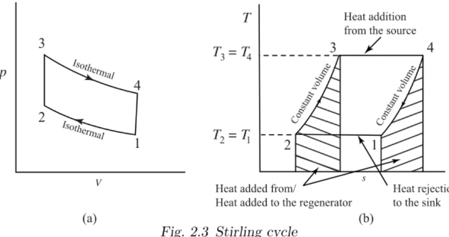
20.9.7 The Stirling Cycle 686
20.9.8 Displacer Type Stirling Engine 687
20.9.9 Pressurization 687
20.9.10 Lubricants and Friction 688
20.9.11 Comparison with Internal Combustion Engines 688 20.9.12 Advantages and Disadvantages of Stirling Engine 688
20.9.13 Applications 691
20.9.14 Future of Stirling Engines 691
20.10 Stratified Charge Engine 692
20.10.1 Advantages of Burning Leaner Overall
Fuel-Air Mixtures 692
20.10.2 Methods of Charge Stratification 695 20.10.3 Stratification by Fuel Injection and Positive Ignition 695 20.10.4 Volkswagen PCI stratified charge engine 696 20.10.5 Broderson Method of Stratification 697 20.10.6 Charge Stratification by Swirl 698
20.10.7 Ford Combustion Process (FCP) 698
20.10.8 Ford PROCO 700
20.10.9 Texaco Combustion Process (TCP) 700 20.10.10 Witzky Swirl Stratification Process 702
20.10.11 Honda CVCC Engine 702
20.10.12 Advantages and Disadvantages of Stratified
Charge Engines 703
20.11 Variable Compression Ratio Engine 704
20.11.1 Cortina Variable Compression Engine 705
20.11.2 Cycle Analysis 706
20.11.3 The CFR Engine 707
20.11.4 Performance of Variable Compression Ratio Engines 707 20.11.5 Variable Compression Ratio Applications 709
20.12 Wankel Engine 709
20.12.1 Basic Design 710
20.12.2 Comparison of Reciprocating and Wankel Rotary Engine712
20.12.3 Materials 712
20.12.4 Sealing 712
20.12.5 Fuel consumption and emissions 712 20.12.6 Advantages and Disadvantages of Wankel Engines 713
Review Questions 714
Multiple Choice Questions 716
Index 719
A
a1 constant
amep mean effective pressure required to drive the auxiliary components
A piston area [Chp.1]
A TEL in ml/gal of fuel [Chp.5]
A area of heat transfer [Chp.14]
A average projected area of each particles [Chp.15]
A1 cross-sectional area at inlet of the carburettor A2 cross-sectional area at venturi of the carburettor Aact actual amount of air in kg for combustion per kg of fuel Af area of cross-section of the fuel nozzle [Chp.7]
Af area of fin [Chp.14]
Ae effective area
Ath theoretical amount of air in kg per kg of fuel A/F air-fuel ratio
B
b1 constant bp brake power bhp brake horsepower
bmep brake mean effective pressure bsf c brake specific fuel consumption BDC Bottom Dead Centre
C
cmep mean effective pressure required to drive the compressor or scavenging pump
C velocity [Chp.7]
Cd coefficient of discharge for the orifice [Chp.7]
Cda coefficient of discharge for the venturi Cdf coefficient of discharge for fuel nozzle Cf fuel velocity at the nozzle exit
Cp specific heat of gas at constant pressure Crel relative charge
Cv specific heat at constant volume CV calorific value of the fuel
D
d cylinder bore diameter [Chp.1]
d diameter of orifice [Chp.7]
D brake drum diameter
E
e expansion ratio E enrichment [Chp.7]
EV C Exhaust Valve Closing EV O Exhaust Valve Opening
F
f coefficient of friction
f mep frictional mean effective pressure f p frictional power
F force
F/A fuel-air ratio
FR relative fuel-air ratio
G
g acceleration due to gravity gc gravitational constant gp gross power
H
h specific enthalpy
h pressure difference [Chp.7]
h convective heat transfer coefficient [Chp.13]
H enthalpy
I
ip indicated power
imep indicated mean effective pressure isf c indicated specific fuel consumption
I intensity
IDC Inner Dead Centre IV C Inlet Valve Closing IV O Inlet Valve Opening
K
k thermal conductivity of gases k1 constant [Chp.3]
K number of cylinders
Kac optical absorption coefficient
L
l characteristic length l distance [Chp.15]
L stroke
Lℓ length of the light path
M
m mass
m exponent [Chp.13]
mep mean effective pressure
mmep mechanical mean effective pressure
˙
ma mass flow rate of air
˙
mact actual mass flow rate of air
˙
mth theoretical mass flow rate of air Mdel mass of fresh air delivered Mf molecular weight of the fuel M molecular weight
Mref reference mass
N
n number of power strokes
n number of soot particles per unit volume [Chp.15]
N speed in revolutions per minute
Ni number of injections per minute [Chp.8]
O
ODC Outer Dead Centre ON Octane Numbers
P
p pressure
pmep charging mean effective pressure
pp pumping power
par pure air ratio
pbm brake mean effective pressure pe exhaust pressure
pi inlet pressure
pim indicated mean effective pressure pm mean effective pressure
Pcyl pressure of charge inside the cylinder Pinj fuel pressure at the inlet to injector Pl pressure loss coefficient
Ps specific power output P N performance number
Q
q heat transfer
˙
q rate of heat transfer
QR heat rejected QS heat supplied
R
r compression ratio
rpn relative performance number rc cut-off ratio
rp pressure ratio
R length of the moment arm R delivery ratio [Chp.19]
R universal gas constant Rdel delivery ratio
S
sp mean piston speed sf c specific fuel consumption S spring scale reading
T
t time
T absolute temperature T torque [Chp.15]
T DC Top Dead Centre Tb black body temperature Tf friction torque
Tg mean gas temperature Tl load torque
U
u specific internal energy U internal energy
Uc chemical energy Us stored energy
V
v specific volume
V volume
Vch volume of cylinder charge Vcp volume of combustion products Vdel volume of air delivered
Vf fuel jet velocity Vpure volume of pure air Vref reference volume Vres volume of residual gas
Vret volume of retained air or mixture
Vs displacement volume Vs swept volume Vshort short circuiting air Vtot total volume VC clearance volume
VT volume at bottom dead centre
W
w specific weight w work transfer [Chp.7]
W net work
W weight [Chp.15]
W number of quartz windows [Chp.15]
W load [Chp.12]
W OT Wide Open Throttle WC compressor work WT turbine work Wx external work
Z
z height of the nozzle exit [Chp.7]
Z constant
GREEK
α air coefficient
γ ratio of specific heats
∆p pressure difference
∆T temperature difference between the gas and the wall ϵ heat exchanger efficiency
η efficiency
ηair std air standard efficiency ηbth brake thermal efficiency ηc compressor efficiency ηch charging efficiency
ηith indicated thermal efficiency ηm mechanical efficiency ηrel relative efficiency ηsc scavenging efficiency ηt turbine efficiency ηth thermal efficiency ηtrap trapping efficiency ηv volumetric efficiency θ crank angle [Chp.11]
θ specific absorbance per particle [Chp.15]
λ wave length [Chp.15]
λ excess air factor [Chp.19]
µ kinematic viscosity of gases ν dynamic viscosity
ρ density
ρf density of fuel ϕ equivalence ratio ψ magnetic field strength ω angular velocity
1
INTRODUCTION
1.1 ENERGY CONVERSION
The distinctive feature of our civilization today, one that makes it different from all others, is the wide use of mechanical power. At one time, the primary source of power for the work of peace or war was chiefly man’s muscles. Later, animals were trained to help and afterwards the wind and the running stream were harnessed. But, the great step was taken in this direction when man learned the art of energy conversion from one form to another. The machine which does this job of energy conversion is called an engine.
1.1.1 Definition of ‘Engine’
An engine is a device which transforms one form of energy into another form.
However, while transforming energy from one form to another, the efficiency of conversion plays an important role. Normally, most of the engines con- vert thermal energy into mechanical work and therefore they are called ‘heat engines’.
1.1.2 Definition of ‘Heat Engine’
Heat engine is a device which transforms the chemical energy of a fuel into thermal energy and utilizes this thermal energy to perform useful work. Thus, thermal energy is converted to mechanical energy in a heat engine.
Heat engines can be broadly classified into two categories:
(i) Internal Combustion Engines (IC Engines) (ii) External Combustion Engines (EC Engines)
1.1.3 Classification and Some Basic Details of Heat Engines
Engines whether Internal Combustion or External Combustion are of two types:
(i) Rotary engines (ii) Reciprocating engines
A detailed classification of heat engines is given in Fig.1.1. Of the various types of heat engines, the most widely used ones are the reciprocating internal combustion engine, the gas turbine and the steam turbine. The steam engine is slowly phased out nowadays. The reciprocating internal combustion engine enjoys some advantages over the steam turbine due to the absence of heat exchangers in the passage of the working fluid (boilers and condensers in steam turbine plant). This results in a considerable mechanical simplicity and improved power plant efficiency of the internal combustion engine.
Heat Engines
IC Engines EC Engines
Rotary Reciprocating Reciprocating Rotary
Open Cycle Gas Turbine
Wankel Engine
Gasoline Engine
Diesel Engine
Steam Engine
Stirling Engine
Steam Turbine
Closed Cycle
Gas Turbine
Fig. 1.1 Classification of heat engines
Another advantage of the reciprocating internal combustion engine over the other two types is that all its components work at an average temperature which is much below the maximum temperature of the working fluid in the cycle. This is because the high temperature of the working fluid in the cycle persists only for a very small fraction of the cycle time. Therefore, very high working fluid temperatures can be employed resulting in higher thermal efficiency.
Further, in internal combustion engines, higher thermal efficiency can be obtained with moderate maximum working pressure of the fluid in the cy- cle, and therefore, the weight to power ratio is quite less compared to steam turbine power plant. Also, it has been possible to develop reciprocating in- ternal combustion engines of very small power output (power output of even a fraction of a kilowatt) with reasonable thermal efficiency and cost.
The main disadvantage of this type of engine is the problem of vibration caused by the reciprocating components. Also, it is not possible to use a vari- ety of fuels in these engines. Only liquid or gaseous fuels of given specification can be effectively used. These fuels are relatively more expensive.
Considering all the above factors the reciprocating internal combustion engines have been found suitable for use in automobiles, motor-cycles and scooters, power boats, ships, slow speed aircraft, locomotives and power units of relatively small output.
1.1.4 External Combustion and Internal Combustion Engines
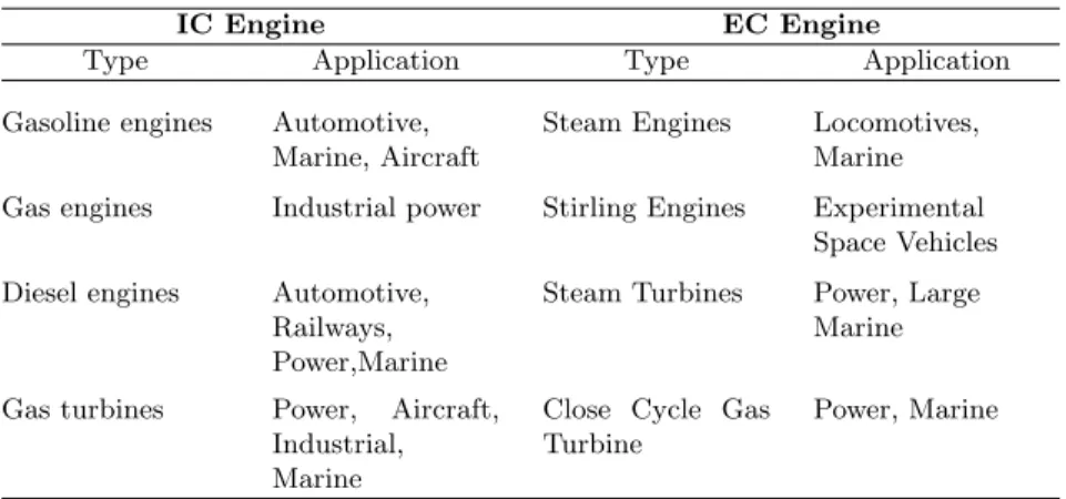
External combustion engines are those in which combustion takes place out- side the engine whereas in internal combustion engines combustion takes place within the engine. For example, in a steam engine or a steam turbine, the heat generated due to the combustion of fuel is employed to generate high pressure steam which is used as the working fluid in a reciprocating engine or a turbine. In case of gasoline or diesel engines, the products of combus- tion generated by the combustion of fuel and air within the cylinder form the working fluid.
1.2 BASIC ENGINE COMPONENTS AND NOMENCLATURE
Even though reciprocating internal combustion engines look quite simple, they are highly complex machines. There are hundreds of components which have to perform their functions effectively to produce output power. There are two types of engines, viz., spark-ignition (SI) and compression-ignition (CI) engine. Let us now go through some of the important engine components and the nomenclature associated with an engine.
1.2.1 Engine Components
A cross section of a single cylinder spark-ignition engine with overhead valves is shown in Fig.1.2. The major components of the engine and their functions are briefly described below.
Inlet valve (IV) Spark plug
Air Fuel
Exhaust valve (EV)
Products
Gudgeon pin Connecting rod
Sump Crankcase Crankpin
Cylinder
Crankshaft Crank
Cylinder block Piston
Inlet manifold Exhaust manifold
Fig. 1.2 Cross-section of a spark-ignition engine
Cylinder Block : The cylinder block is the main supporting structure for the various components. The cylinder of a multicylinder engine are cast as a single unit, called cylinder block. The cylinder head is mounted on the cylinder block. The cylinder head and cylinder block are provided with water jackets in the case of water cooling or with cooling fins in the case of air cooling. Cylinder head gasket is incorporated between the cylinder block and cylinder head. The cylinder head is held tight to the cylinder block by number of bolts or studs. The bottom portion of the cylinder block is called crankcase.
A cover called crankcase which becomes a sump for lubricating oil is fastened to the bottom of the crankcase. The inner surface of the cylinder block which is machined and finished accurately to cylindrical shape is called bore or face.
Cylinder : As the name implies it is a cylindrical vessel or space in which the piston makes a reciprocating motion. The varying volume created in the cylinder during the operation of the engine is filled with the working fluid and
subjected to different thermodynamic processes. The cylinder is supported in the cylinder block.
Piston : It is a cylindrical component fitted into the cylinder forming the moving boundary of the combustion system. It fits perfectly (snugly) into the cylinder providing a gas-tight space with the piston rings and the lubricant.
It forms the first link in transmitting the gas forces to the output shaft.
Combustion Chamber : The space enclosed in the upper part of the cylin- der, by the cylinder head and the piston top during the combustion process, is called the combustion chamber. The combustion of fuel and the consequent release of thermal energy results in the building up of pressure in this part of the cylinder.
Inlet Manifold : The pipe which connects the intake system to the inlet valve of the engine and through which air or air-fuel mixture is drawn into the cylinder is called the inlet manifold.
Exhaust Manifold : The pipe which connects the exhaust system to the exhaust valve of the engine and through which the products of combustion escape into the atmosphere is called the exhaust manifold.
Inlet and Exhaust Valves : Valves are commonly mushroom shaped pop- pet type. They are provided either on the cylinder head or on the side of the cylinder for regulating the charge coming into the cylinder (inlet valve) and for discharging the products of combustion (exhaust valve) from the cylinder.
Spark Plug : It is a component to initiate the combustion process in Spark- Ignition (SI) engines and is usually located on the cylinder head.
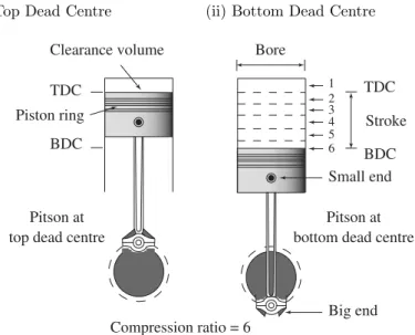
Connecting Rod : It interconnects the piston and the crankshaft and trans- mits the gas forces from the piston to the crankshaft. The two ends of the connecting rod are called as small end and the big end (Fig.1.3). Small end is connected to the piston by gudgeon pin and the big end is connected to the crankshaft by crankpin.
Crankshaft : It converts the reciprocating motion of the piston into useful rotary motion of the output shaft. In the crankshaft of a single cylinder engine there are a pair of crank arms and balance weights. The balance weights are provided for static and dynamic balancing of the rotating system.
The crankshaft is enclosed in a crankcase.
Piston Rings : Piston rings, fitted into the slots around the piston, provide a tight seal between the piston and the cylinder wall thus preventing leakage of combustion gases (refer Fig.1.3).
Gudgeon Pin : It links the small end of the connecting rod and the piston.
Camshaft : The camshaft (not shown in the figure) and its associated parts control the opening and closing of the two valves. The associated parts are push rods, rocker arms, valve springs and tappets. This shaft also provides the drive to the ignition system. The camshaft is driven by the crankshaft through timing gears.
Cams : These are made as integral parts of the camshaft and are so de- signed to open the valves at the correct timing and to keep them open for the necessary duration (not shown in the figure).
Fly Wheel : The net torque imparted to the crankshaft during one complete cycle of operation of the engine fluctuates causing a change in the angular
velocity of the shaft. In order to achieve a uniform torque an inertia mass in the form of a wheel is attached to the output shaft and this wheel is called the flywheel (not shown in the figure).
1.2.2 Nomenclature
Cylinder Bore (d) : The nominal inner diameter of the working cylinder is called the cylinder bore and is designated by the letter d and is usually expressed in millimeter (mm).
Piston Area (A): The area of a circle of diameter equal to the cylinder bore is called the piston area and is designated by the letterAand is usually expressed in square centimeter (cm2).
Stroke (L) : The nominal distance through which a working piston moves between two successive reversals of its direction of motion is called the stroke and is designated by the letterLand is expressed usually in millimeter (mm).
Stroke to Bore Ratio : L/dratio is an important parameter in classifying the size of the engine. Ifd < L, it is called under-square engine. Ifd=L, it is called square engine. Ifd > L, it is called over-square engine.
An over-square engine can operate at higher speeds because of larger bore and shorter stroke.
Dead Centre : The position of the working piston and the moving parts which are mechanically connected to it, at the moment when the direction of the piston motion is reversed at either end of the stroke is called the dead centre. There are two dead centres in the engine as indicated in Fig.1.3. They are:
(i) Top Dead Centre (ii) Bottom Dead Centre
TDC
Bore
Stroke TDC
BDC
Compression ratio = 6 top dead centre
Pitson at
bottom dead centre Pitson at Clearance volume
BDC
1 2 3 4 5 6
Piston ring
Small end
Big end
Fig. 1.3 Top and bottom dead centres
(i) Top Dead Centre(T DC): It is the dead centre when the piston is far- thest from the crankshaft. It is designated asT DC for vertical engines and Inner Dead Centre (IDC) for horizontal engines.
(ii) Bottom Dead Centre(BDC): It is the dead centre when the piston is nearest to the crankshaft. It is designated asBDCfor vertical engines and Outer Dead Centre (ODC) for horizontal engines.
Displacement or Swept Volume (Vs) : The nominal volume swept by the working piston when travelling from one dead centre to the other is called the displacement volume. It is expressed in terms of cubic centimeter (cc) and given by
Vs=A×L = π
4d2L (1.1)
Cubic Capacity or Engine Capacity : The displacement volume of a cylinder multiplied by number of cylinders in an engine will give the cubic capacity or the engine capacity. For example, if there areK cylinders in an engine, then
Cubic capacity =Vs×K
Clearance Volume(VC): The nominal volume of the combustion chamber above the piston when it is at the top dead centre is the clearance volume. It is designated asVC and expressed in cubic centimeter (cc).
Compression Ratio(r): It is the ratio of the total cylinder volume when the piston is at the bottom dead centre,VT, to the clearance volume,VC. It is designated by the letterr.
r= VT
VC
=VC+Vs
VC
= 1 + Vs
VC
(1.2) 1.3 THE WORKING PRINCIPLE OF ENGINES
If an engine is to work successfully then it has to follow a cycle of operations in a sequential manner. The sequence is quite rigid and cannot be changed.
In the following sections the working principle of both SI and CI engines is described. Even though both engines have much in common there are certain fundamental differences.
The credit of inventing the spark-ignition engine goes to Nicolaus A.
Otto (1876) whereas compression-ignition engine was invented by Rudolf Diesel (1892). Therefore, they are often referred to as Otto engine and Diesel engine.
1.3.1 Four-Stroke Spark-Ignition Engine
In a four-stroke engine, the cycle of operations is completed in four strokes of the piston or two revolutions of the crankshaft. During the four strokes, there are five events to be completed, viz., suction, compression, combustion, expansion and exhaust. Each stroke consists of 180◦ of crankshaft rotation and hence a four-stroke cycle is completed through 720◦ of crank rotation.
The cycle of operation for an ideal four-stroke SI engine consists of the fol- lowing four strokes : (i) suction or intake stroke; (ii) compression stroke; (iii) expansion or power stroke and (iv) exhaust stroke.
The details of various processes of a four-stroke spark-ignition engine with overhead valves are shown in Fig.1.4 (a-d). When the engine completes all
the five events under ideal cycle mode, the pressure-volume (p-V) diagram will be as shown in Fig.1.5.
(d) Exhaust (c) Expansion
(b) Compression (a) Intake
Fig. 1.4 Working principle of a four-stroke SI engine
2 0 3
4 1-5 p
Vs V Vc
Fig. 1.5 Idealp-V diagram of a four-stroke SI engine
(i) Suction or Intake Stroke : Suction stroke 0→1 (Fig.1.5) starts when the piston is at the top dead centre and about to move downwards.
The inlet valve is assumed to open instantaneously and at this time the exhaust valve is in the closed position, Fig.1.4(a). Due to the suction created by the motion of the piston towards the bottom dead centre, the charge consisting of fuel-air mixture is drawn into the cylinder. When the piston reaches the bottom dead centre the suction stroke ends and the inlet valve closes instantaneously.
(ii) Compression Stroke : The charge taken into the cylinder during the suction stroke is compressed by the return stroke of the piston 1→2, (Fig.1.5). During this stroke both inlet and exhaust valves are in closed position, Fig.1.4(b). The mixture which fills the entire cylinder vol- ume is now compressed into the clearance volume. At the end of the compression stroke the mixture is ignited with the help of a spark plug located on the cylinder head. In ideal engines it is assumed that burning takes place instantaneously when the piston is at the top dead centre and hence the burning process can be approximated as heat addition
at constant volume. During the burning process the chemical energy of the fuel is converted into heat energy producing a temperature rise of about 2000 ◦C (process 2→3), Fig.1.5. The pressure at the end of the combustion process is considerably increased due to the heat release from the fuel.
(iii) Expansion or Power Stroke : The high pressure of the burnt gases forces the piston towards the BDC, (stroke 3→4) Fig.1.5. Both the valves are in closed position, Fig.1.4(c). Of the four-strokes only during this stroke power is produced. Both pressure and temperature decrease during expansion.
(iv) Exhaust Stroke : At the end of the expansion stroke the exhaust valve opens instantaneously and the inlet valve remains closed, Fig.1.4(d).
The pressure falls to atmospheric level a part of the burnt gases escape.
The piston starts moving from the bottom dead centre to top dead centre (stroke 5→0), Fig.1.5 and sweeps the burnt gases out from the cylinder almost at atmospheric pressure. The exhaust valve closes when the piston reaches T DC. at the end of the exhaust stroke and some residual gases trapped in the clearance volume remain in the cylinder.
These residual gases mix with the fresh charge coming in during the following cycle, forming its working fluid. Each cylinder of a four-stroke engine completes the above four operations in two engine revolutions, first revolution of the crankshaft occurs during the suction and compres- sion strokes and the second revolution during the power and exhaust strokes. Thus for one complete cycle there is only one power stroke while the crankshaft makes two revolutions. For getting higher output from the engine the heat addition (process 2→3) should be as high as possible and the heat rejection (process 3→4) should be as small as pos- sible. Hence, one should be careful in drawing the ideal p-V diagram (Fig.1.5), which should depict the processes correctly.
1.3.2 Four-Stroke Compression-Ignition Engine
The four-stroke CI engine is similar to the four-stroke SI engine but it operates at a much higher compression ratio. The compression ratio of an SI engine is between 6 and 10 while for a CI engine it is from 16 to 20. In the CI engine during suction stroke, air, instead of a fuel-air mixture, is inducted.
Due to higher compression ratios employed, the temperature at the end of the compression stroke is sufficiently high to self ignite the fuel which is injected into the combustion chamber. In CI engines, a high pressure fuel pump and an injector are provided to inject the fuel into the combustion chamber. The carburettor and ignition system necessary in the SI engine are not required in the CI engine.
The ideal sequence of operations for the four-stroke CI engine as shown in Fig.1.6 is as follows:
(i) Suction Stroke : Air alone is inducted during the suction stroke. During this stroke inlet valve is open and exhaust valve is closed, Fig.1.6(a).
(c) Expansion
IV EV
(d) Exhaust
IV EV
(a) Suction
IV EV
(b) Compression
IV EV
Fig. 1.6 Cycle of operation of a CI engine
(ii) Compression Stroke : Air inducted during the suction stroke is com- pressed into the clearance volume. Both valves remain closed during this stroke, Fig.1.6(b).
(iii) Expansion Stroke : Fuel injection starts nearly at the end of the com- pression stroke. The rate of injection is such that combustion maintains the pressure constant in spite of the piston movement on its expansion stroke increasing the volume. Heat is assumed to have been added at constant pressure. After the injection of fuel is completed (i.e. after cut-off) the products of combustion expand. Both the valves remain closed during the expansion stroke, Fig.1.6(c).
(iv) Exhaust Stroke : The piston travelling fromBDCtoT DCpushes out the products of combustion. The exhaust valve is open and the intake valve is closed during this stroke, Fig.1.6(d). The idealp-V diagram is shown in Fig.1.7.
V p
2
1-5 3
4
0 p = p
3 2
Fig. 1.7 Idealp-V diagram for a four-stroke CI engine
Due to higher pressures in the cycle of operations the CI engine has to be sturdier than a SI engine for the same output. This results in a CI engine being heavier than the SI engine. However, it has a higher thermal efficiency