NCL1170 User Guide
Version A
WaveRider Communications Inc.
Software License Agreement
This is a legal agreement between you (either an individual or an entity) and WaveRider Communications Inc. for the use of WaveRider computer software, hereinafter the “LICENSED SOFTWARE”.
By using the LICENSED SOFTWARE installed in this product, you acknowledge that you have read this license agreement, understand it, and agree to be bound by its terms. You further agree that it is the full and complete agreement between you and WaveRider Communications Inc., superseding all prior written or verbal agreements of any kind related to the LICENSED SOFTWARE. If you do not understand or do not agree to the terms of this agreement, you will cease using the LICENSED SOFTWARE immediately.
1 GRANT OF LICENSE—This License Agreement permits you to use one copy of the LICENSED SOFTWARE.
2. COPYRIGHT—The LICENSED SOFTWARE is owned by WaveRider Communications Inc. and is protected by copyright laws and international treaty provisions; therefore, you must treat the LICENSED SOFTWARE like any other copyrighted material (e.g., a book or magazine). You may not copy the written materials
accompanying the LICENSED SOFTWARE.
3. OTHER RESTRICTIONS—You may not rent or lease the LICENSED SOFTWARE. You may not reverse engineer, decompile, or disassemble the LICENSED SOFTWARE.
4. LIMITED WARRANTY—The LICENSED SOFTWARE is provided “as is” without any warranty of any kind, either expressed or implied, including, but not limited to, the implied warranties of merchantability and fitness for a particular purpose. The entire risk as to the quality and performance of the LICENSED SOFTWARE is with you, the licensee. If the LICENSED SOFTWARE is defective, you assume the risk and liability for the entire cost of all necessary repair, service, or correction.
Some states/jurisdictions do not allow the exclusion of implied warranties, so the above exclusion may not apply to you. This warranty gives you specific legal rights, and you may have other rights, which vary from state/jurisdiction to state/jurisdiction.
WaveRider Communications Inc. does not warrant that the functions contained in the LICENSED SOFTWARE will meet your requirements, or that the operation of the LICENSED SOFTWARE will be error-free or uninterrupted.
5. NO OTHER WARRANTIES—To the maximum extent permitted by applicable law, WaveRider Communications Inc. disclaims all other warranties, either express or implied, including, but not limited to, the implied warranties of merchantability and fitness for a particular purpose, with regard to the LICENSED SOFTWARE and the accompanying written materials.
6. NO LIABILITY FOR CONSEQUENTIAL DAMAGES—To the maximum extent permitted by applicable law, in no event shall WaveRider Communications Inc. or its suppliers be liable for any damages whatsoever (including, without limitation, damages for loss of business profits, business interruption, loss of business information, or any other pecuniary loss) arising from the use of or inability to use the LICENSED SOFTWARE, even if WaveRider Communications Inc. has been advised of the possibility of such damages, or for any claim by any other party.
Because some states/jurisdictions do not allow the exclusion or limitation of liability for consequential or incidental damages, the above limitation may not apply to you.
In no event will WaveRider’s liability exceed the amount paid for the LICENSED SOFTWARE.
The following are trademarks or registered trademarks of their respective companies or organizations:
Microsoft Internet Explorer/Microsoft Corporation Netscape/Netscape Communications Corporation
© 2001 by WaveRider Communications Inc. All rights reserved. This manual may not be reproduced by any means in whole or in part without the express written permission of WaveRider Communications Inc.
Version A, January 2001
Warranty
In the following warranty text, “WaveRider®” shall mean WaveRider Communications Inc.
This WaveRider product is warranted against defects in material and workmanship for a period of one (1) year from the date of purchase. This limited warranty extends only to the original purchaser. During this warranty period WaveRider will, at its option, either repair or replace products that prove to be defective.
For warranty service or repair, the product must be returned to a service facility designated by WaveRider. Authorization to return products must be obtained prior to shipment. The WaveRider RMA number must be on the shipping documentation so that the service facility will accept the product. The buyer shall pay all shipping charges to WaveRider and WaveRider shall pay shipping charges to return the product to the buyer within Canada or the USA. For all other countries, the buyer shall pay shipping charges as well as duties and taxes incurred in shipping products to or from WaveRider.
WaveRider warrants that the firmware designed by it for use with the unit will execute its programming instructions when properly installed on the unit. WaveRider does not warrant that the operation of the unit or firmware will be uninterrupted or error-free.
Limitation of Warranty
The foregoing warranty shall not apply to defects resulting from improper or inadequate maintenance by the buyer, buyer-supplied interfacing, unauthorized modification or misuse, operation outside the environmental specifications for the product, or improper site preparation or maintenance or exposure to abnormal physical or electrical stress or accident. No other warranty is expressed or implied. WaveRider specifically disclaims the implied warranties of merchantability and fitness for any particular purpose.
No Liability for Consequential Damages
To the maximum extent permitted by applicable law, in no event shall WaveRider or its suppliers be liable for any damages whatsoever (including, without limitation, damages for loss of business profits, business interruption, loss of business information, or any other pecuniary loss) arising from the use of or inability to use the product, even if WaveRider has been advised of the possibility of such damages, or for any claim by any other party.
Because some states/jurisdictions do not allow the exclusion or limitation of liability for consequential or incidental damages, the above limitation may not apply to you.
In no event will WaveRider’s liability exceed the amount paid for the product.
Regulatory Notices
This equipment has been tested and found to comply with the limits for a Class A Intentional Radiator, pursuant to Part 15 of the FCC Regulations, and RSS-210 of the IC Regulations. These limits are intended to provide protection against harmful interference when the equipment is operated in a commercial/business/industrial environment.
This equipment generates, uses, and can radiate radio frequency energy and, if not installed and used in accordance with the instruction manual, may cause harmful interference to radio communications. However, there is no guarantee that interference will not occur in a particular installation.
Any changes or modifications to equipment that are not expressly approved by the manufacturer may void the user’s authority to operate the equipment. The NCL1170 contains no user-serviceable parts. Unauthorized opening of the unit voids this warranty.
Contents
Preface . . . .ix
1 NCL1170 Overview . . . 1
1.1 Introduction . . . 1
1.2 Features. . . 2
1.3 About Spread-Spectrum Radio Technology . . . 3
2 Network Considerations . . . 5
2.1 Network Topology . . . 5
2.1.1 Point-to-Multipoint . . . 6
2.1.2 Point-to-Point . . . 7
2.1.3 Repeater . . . 7
2.2 Bridging and Routing Network Configurations . . . 8
2.2.1 Point-to-Multipoint Bridging Network . . . 8
2.2.2 Point-to-Multipoint Routing Networks . . . 9
2.3 Planning an NCL1170 Configuration . . . 10
3 Installing the NCL1170 . . . 11
3.1 Connecting the NCL1170. . . 12
3.2 Initializing the NCL1170 . . . 14
3.2.1 Changing the NCL1170 Password . . . 15
3.2.2 Setting the NCL1170 System Name . . . 16
3.2.3 Resetting an NCL1170 to Factory Defaults . . . 16
4 Configuring the NCL1170 . . . 17
4.1 Setting the Radio Configuration . . . 18
4.2 Setting the IP Configuration . . . 19
4.3 Configuration Options . . . 20
4.3.1 Setting RIP Configuration . . . 20
4.3.2 Setting the DHCP Relay Configuration . . . 22
4.3.3 Setting the SNMP Configuration . . . 22
4.3.4 Setting the DNS Resolver Configuration . . . 23
4.4 Examples of Bridging and Routing Configurations . . . 24
4.4.1 Point-to-Multipoint Bridging Network . . . 24
4.4.2 Point-to-Multipoint Routing Network . . . 27
4.5 Updating an NCL1170 Using Remote Connections. . . 32
4.5.1 Establishing an FTP Connection . . . 32
vi APCD–NC006–A
5.2.1 Running the Continuous Transmit (Tx) Test . . . 37
5.2.2 Running the Continuous Receive (Rx) Test . . . 38
5.2.3 Performing the Transmit/Receive Loopback Test . . . 41
6 System Reporting and Diagnostics . . . 43
6.1 Radio Receive Signal Strength Indication (RSSI) . . . 43
6.2 Radio Packet Error Rate (PER) . . . 44
6.3 Interface Statistics . . . 47
6.3.1 IP Statistics . . . 50
6.3.2 Radio Statistics . . . 52
7 Troubleshooting . . . 53
7.1 Verifying NCL1170 Routing . . . 55
7.1.1 Verify the NCL1170 Routing Table . . . 55
Appendix A NCL1170 Command-Line Syntax . . . 57
Appendix B Abbreviations and Terminology . . . 67
Appendix C Operating Channel Frequencies . . . 73
Appendix D NCL1170 Specifications . . . 75
Appendix E Configuration Data Record . . . 79
Figures
Figure 1 The NCL1170 . . . 1
Figure 2 Point-to-Multipoint Application . . . 6
Figure 3 Point-to-Point Application . . . 7
Figure 4 Repeater Application . . . 7
Figure 5 Point-to-Multipoint Bridging Network Example . . . 8
Figure 6 Point-to-Multipoint Routing Network Example . . . 9
Figure 7 NCL1170 Configuration Planning Flowchart . . . 10
Figure 8 NCL1170 Connectors and Indicators . . . 12
Figure 9 Console Port Pin-out Diagram . . . 13
Figure 10 Example of Point-to-Multipoint Bridging Network . . . 24
Figure 11 Example of Point-to-Multipoint Routing Network . . . 27
viii APCD–NC006–A
Tables
Table 1 Radio Packet Error Rate Assessment . . . 46
Table 2 Interface Statistics . . . 49
Table 3 IP Statistics . . . 51
Table 4 Radio Statistics . . . 52
Table 5 Common Problems and Solutions . . . 53
Table 6 NCL1170 Command-Line Syntax Conventions . . . 57
Table 7 Command-Line Shortcuts and Getting Help . . . 58
Table 8 NCL1170 Command-line Syntax Descriptions . . . 58
Table 9 Acronyms and Abbreviations . . . 67
Table 10 NCL1170 Network Terminology . . . 70
Table 11 Network Interface . . . 75
Table 12 Physical Interface . . . 75
Table 13 Radio Performance . . . 75
Table 14 Power Supply . . . 76
Table 15 Environmental Considerations . . . 76
Table 16 Regulatory . . . 76
Preface
About this Guide
This document provides a complete overview of the WaveRider NCL1170 bridge/router, including system features, network planning, and procedures for implementing, installing, operating, and troubleshooting this device.
Before proceeding, we recommend that you read the following sections:
• Software License Agreement on page ii
• Warranty on page iv
• Regulatory Notices on page x
• Warnings and Advisories on page xii
x APCD–NC006–A
Regulatory Notices
Industry Canada
The NCL1170 complies with IC RSS–210.
Operators must be familiar with IC RSS–210 and RSS–102.
The IC certification number for the NCL1170 is “pending”.
WARNING!
To prevent radio interference to the licensed service, this device is intended to be operated indoors and away from windows to provide maximum shielding. Equipment (or its transmit antenna) that is installed outdoors is subject to licensing.
Federal Communications Commission
The NCL1170 complies with FCC Part 15 Regulations.
The FCC ID for the NCL1170 is OOX-WRM2000.
The transmitter of this device complies with Part 15.247 of the FCC Rules.
WARNING!
Operators must be familiar with the requirements of the FCC Part 15 Regulations prior to operating any link using this equipment. For installations outside the United States, contact local authorities for applicable regulations.
Interference Environment
Manufacturers and operators of spread-spectrum devices are reminded that the operation of these devices is subject to the conditions that:
• Any received interference, including interference from industrial, scientific, and medical (ISM) operations, must be accepted; and
• These devices are not permitted to cause harmful interference to other radio services.
If the operation of these systems does cause harmful interference, the operator of the spread- spectrum system must correct the interference problem, even if such correction requires the Part 15 transmitter to cease operation. The FCC does not exempt spread-spectrum devices from this latter requirement regardless of the application. The FCC strongly recommends that utilities, cellular stations, public safety services, government agencies, and others that provide
critical communication services exercise due caution to determine if there are any nearby radio services that can be affected by their communications.
Operational Requirements
In accordance with the FCC Part 15 regulations:
1. The maximum peak power output of the intentional radiator shall not exceed one (1) watt for all spread-spectrum systems operating in the 2.4000-2.4835 GHz band.
2. Systems operating in the 2.4000-2.4835 GHz band that are used exclusively for fixed, point-to-point operations may employ transmitting antennas with directional gain greater than 6 dBi, provided the maximum peak output power of the intentional radiator is reduced by 1 dB for every 3 dB that the directional gain of the antenna exceeds 6 dBi.
3. Stations operating in the 2.4000-2.4835 GHz band that are used for fixed, point-to- multipoint operations may use transmitting antennas of directional gain greater that 6 dBi, provided the peak output power from the intentional radiator is reduced by the amount in dB that the directional gain of the antenna exceeds 6 dBi.
4. Fixed, point-to-point operation, as used in Point 2, excludes the use of point-to- multipoint systems, omni-directional applications, and multiple co-located intentional radiators transmitting the same information. The operator of the spread-spectrum intentional radiator or, if the equipment is professionally installed, the installer is responsible for ensuring that the system is used exclusively for fixed, point-to-point operations.
5. The operator of a spread-spectrum system is responsible for ensuring that the system is operated in the manner outlined in Interference Environment on page x.
xii APCD–NC006–A
Warnings and Advisories
General Advisory
Operator and maintenance personnel must be familiar with the related safety requirements before they attempt to install or operate the NCL1170 equipment.
It is the responsibility of the operator to ensure that the public is not exposed to excessive Radio Frequency (RF) levels. The applicable regulations can be obtained from local authorities.
WARNING!
This system must be professionally installed. Antennas and associated transmission cable must be installed by qualified personnel. WaveRider assumes no liability for failure to adhere to this recommendation or to recognized general safety precautions.
WARNING!
To comply with FCC RF exposure limits, the antenna for this transmitter must be fix-mounted on outdoor permanent structures to provide a separation distance of 2 metres (6.6 feet) from all persons to satisfy RF exposure requirements. The distance is measured from the front of the antenna and the human body. It is recommended that the antenna be installed in a location with minimal pathway disruption by nearby personnel.
WARNING!
Do not operate the NCL1170 without connecting a 50-ohm termination to the antenna port. This termination can be a 50-ohm antenna or a 50-ohm resistive load capable of absorbing the full RF output power of the transceiver. Failure to terminate the antenna port properly may cause permanent damage to the NCL1170.
WARNING!
Connect only shielded twisted pair (STP) Ethernet cable to the NCL1170 10Base Tx Ethernet (RJ-45) port. It is the responsibility of the installer to supply and use the correct type of Ethernet cable.
Customer Support
If you have any problems with the hardware or software, please contact WaveRider
Communications Inc. Please provide your NCL1170 model number and software version when requesting support.
WaveRider offers a complete training program. Please contact your sales representative for training information.
Telephone: +1 416–502–3161 Fax: +1 416–502–2968 Email: Product Assistance:
[email protected] URL: www.waverider.com
— This page is intentionally left blank —
1 NCL1170 Overview
1.1 Introduction
The NCL1170 is an intelligent, wireless Internet Protocol (IP) bridge/router that provides high- capacity 2.4 GHz connections between local- and wide-area networks via broadband radio links. Employing Direct-Sequence Spread Spectrum (DSSS) transmission techniques, the NCL1170 allows you to access the Internet at high speeds, extend Ethernet networks, and connect to remote locations without the ongoing costs of leased telephone or data lines.
1 NCL1170 Overview
2 APCD–NC006–A
1.2 Features
• Flexible deployment—the NCL1170 can operate as either a bridge or router. In routing mode, you can set up the NCL1170 to use communications strategies such as Routing Information Protocol (RIP), and Dynamic Host Control Protocol (DHCP).
• Ethernet compatibility—the NCL1170 allows users to connect with most Ethernet networks or devices.
• Microprocessor-controlled signal processing—all functions of WaveRider’s spread-spectrum transceiver are controlled through the integration of a powerful on board microprocessor.
• Architectural flexibility—you can set up NCL1170s as separate point-to-point links, or in a mulitipoint configuration. A single NCL1170 operating in “master” mode can deliver data to and receive data from up to 20 NCL1170s operating in “station” mode.
• User-configurable operating system—you can upgrade the NCL1170 remotely via FTP.
• User-customizable monitoring—the NCL1170 operating system supports Simple Network Management Protocol (SNMP), which allows for continual status monitoring of any NCL1170 in your network.
• Low interference—Direct Sequence Spread-Spectrum (DSSS) technology transmits signal information over a wide channel bandwidth, which reduces the potential for interference with neighboring communications systems. The NCL1170 design permits three master units to operate in close proximity without interfering with each other. For example, three master units supporting 20 station units each can operate in close proximity, thus providing 60 end-user links.
1 NCL1170 Overview
1.3 About Spread-Spectrum Radio Technology
Spread-spectrum communications systems differ from conventional narrowband
communications systems because they use a much larger transmission bandwidth to send the same amount of information.
There are two primary forms of spread spectrum—direct sequence and frequency hopping.
The NCL1170 uses Direct-Sequence Spread-Spectrum (DSSS). In DSSS systems, the transmitted information, along with a digital spreading sequence, are used to modulate the transmit carrier. The received signal is de-spread using the same digital spreading sequence, and the information recovered.
Although spread spectrum appears complex and uses a wider bandwidth, the use of DSSS offers the following advantages:
• Reduced power spectral density—Spreading over a wider bandwidth reduces the spectral density (power per Hz of bandwidth) of the transmitted signal, allowing simultaneous operation of many spread spectrum systems in the same frequency band and geographic area. The reduced spectral density also allows you meet the regulatory emissions requirements in frequency bands such as the ISM band.
• Transmission security—It is technologically more difficult to surreptitiously recover (or jam, in the case of military communications systems) spread-spectrum signals than it is to recover conventional narrowband signals.
• Interference suppression—The same mechanism that de-spreads the desired signal in the receiver, also spreads undesired signals, which then appear to the receiver as lower levels of RF noise.
For more information about spread spectrum communications, contact the WaveRider Product Assistance.
— This page is intentionally left blank —
2 Network Considerations
How you configure your NCL1170 depends on its intended role in your network.
Before proceeding, answer the following questions:
• What network topology will I be implementing?
• Will my NCL1170 be operating in bridging or routing mode?
• Have I developed a network plan?
2.1 Network Topology
The NCL1170 can be deployed in three different network configurations:
• point-to-multipoint
• point-to-point
• repeater
Regardless of network configuration, each NCL1170 must be installed as either a bridge or router; it cannot operate simultaneously in both modes.
2 Network Considerations
6 APCD–NC006–A
2.1.1 Point-to-Multipoint
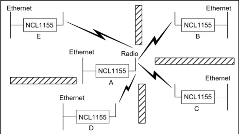
In a typical point-to-multipoint application (see Figure 2) a designated master unit A, transmits and receives data among station units B, C, D, and E, which are programmed to communicate with each other only through their master unit. In this type of configuration, the throughput of unit A is shared among all stations.
Figure 2 Point-to-Multipoint Application Radio
Ethernet
C NCL1155
Ethernet
B NCL1155
D Ethernet
NCL1155 E
NCL1155 Ethernet
Ethernet
A NCL1155
2 Network Considerations
2.1.2 Point-to-Point
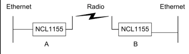
In a typical point-to-point application, (see Figure 3), unit A communicates directly with unit B.
The NCL1170 can perform this type of link in either bridging or routing mode.
Figure 3 Point-to-Point Application
2.1.3 Repeater
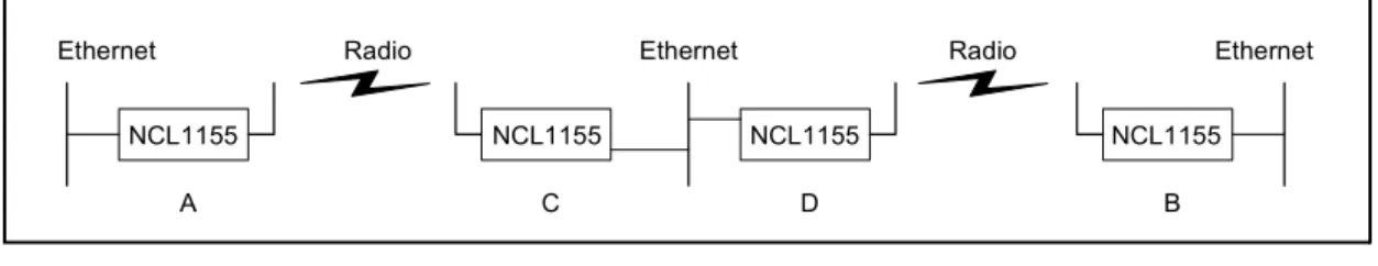
In a typical repeater application, (see Figure 4), unit A communicates with unit B via back-to- back NCL1170 units C and D, with different frequencies used for each leg of the path. You would implement an NCL1170 in a repeater configuration whenever you need to circumvent large obstacles in the radio link path, or when the link from unit A to unit B is too long to maintain reasonable signal levels and data throughput.
Figure 4 Repeater Application
In this configuration, the effective data throughput among any combination of units is equal to or less than the throughput between the slowest links.
NCL1155 NCL1155
A B
Ethernet Radio Ethernet
B NCL1155
Ethernet Radio Ethernet Radio Ethernet
A C D
NCL1155 NCL1155 NCL1155
2 Network Considerations
8 APCD–NC006–A
2.2 Bridging and Routing Network Configurations
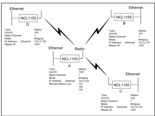
2.2.1 Point-to-Multipoint Bridging Network
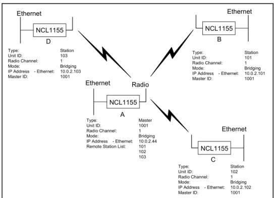
In a typical point-to-multipoint bridging network, (see Figure 5) unit A is installed as the network master, with units B, C, and D configured as stations, each defined by two network parameters:
• Master ID—which must be the same as the Unit ID for A.
• Unit ID—which must be added to the Remote Station List for A before it can be recognized as a network device.
If a station has a Master ID that does not match the unit ID for A, or it is not on the Master Remote Station List for A, it will not be able to communicate across the network.
Figure 5 Point-to-Multipoint Bridging Network Example Ethernet NCL1155
C
Ethernet NCL1155
B Ethernet
NCL1155 D
Ethernet Radio NCL1155
A
Type: Station
Unit ID: 103
Radio Channel: 1
Mode: Bridging
IP Address - Ethernet: 10.0.2.103
Master ID: 1001
Type: Station
Unit ID: 102
Radio Channel: 1
Mode: Bridging
IP Address - Ethernet: 10.0.2.102
Master ID: 1001
Type: Station
Unit ID: 101
Radio Channel: 1
Mode: Bridging
IP Address - Ethernet: 10.0.2.101
Master ID: 1001
Type: Master
Unit ID: 1001
Radio Channel: 1
Mode: Bridging
IP Address - Ethernet: 10.0.2.44 Remote Station List: 101
102 103
2 Network Considerations
2.2.2 Point-to-Multipoint Routing Networks
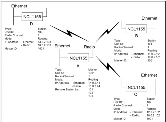
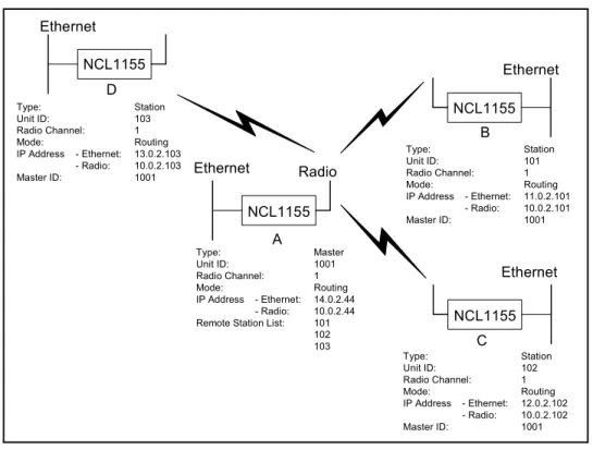
In a typical point-to-multipoint routing network, (see Figure 6), NCL1170 unit A is dedicated as a router, while NCL1170 units B through D are operating in Station mode as gateways to their respective networks.
Figure 6 Point-to-Multipoint Routing Network Example Ethernet NCL1155
C
Ethernet NCL1155
B Ethernet
NCL1155 D
Ethernet Radio NCL1155
A
Type: Station
Unit ID: 103
Radio Channel: 1
Mode: Routing
IP Address - Ethernet: 13.0.2.103 - Radio: 10.0.2.103
Master ID: 1001
Type: Station
Unit ID: 102
Radio Channel: 1
Mode: Routing
IP Address - Ethernet: 12.0.2.102 - Radio: 10.0.2.102
Master ID: 1001
Type: Station
Unit ID: 101
Radio Channel: 1
Mode: Routing
IP Address - Ethernet: 11.0.2.101 - Radio: 10.0.2.101
Master ID: 1001
Type: Master
Unit ID: 1001
Radio Channel: 1
Mode: Routing
IP Address - Ethernet: 14.0.2.44 - Radio: 10.0.2.44 Remote Station List: 101
102 103
2 Network Considerations
10 APCD–NC006–A
2.3 Planning an NCL1170 Configuration
Configuring each NCL1170 correctly is crucial to the proper operation of your network. Review the flowchart in Figure 7 before starting the configuration to ensure that you have the
necessary information to configure the unit correctly.
Record your configuration options for each unit in a configuration record similar to the one provided in Appendix E. Use the Configuration Data Record to help you plan your network and keep track of NCL1170 network assignments.
Figure 7 NCL1170 Configuration Planning Flowchart
Start NCL1155 Configuration
Determine IP address and subnet mask for Ethernet
interface
Bridging or Routing?
Determine IP address and subnet mask for
radio interface
(Optional) Determine SNMP
configuration
Determine static routes
(Optional) Determine DNS server
configuration
End NCL1155 Configuration
Routing
Bridge IP Configuration
(Optional) Determine DHCP Relay
configuration (Optional)
Determine static routes Master or
Station?
Determine radio channel
Determine station unit IDs for Remote Station
List
Determine master unit ID Station
Master
Radio Configuration
(Optional) Determine RIP
configuration Determine unit ID
3 Installing the NCL1170
This section describes the steps required to connect and initialize the NCL1170 hardware prior to configuring the device as a bridge or router.
WARNING!
Antennas and associated transmission cable must be installed by qualified personnel. Failure to terminate the antenna port correctly can permanently damage the NCL1170. WaveRider assumes no liability for failure to adhere to this recommendation or to recognized general safety precautions.
WARNING!
Connect only shielded twisted pair (STP) Ethernet cable to the 10Base Tx Ethernet (RJ-45) port on the NCL1170. It is the responsibility of the installer to supply and use the correct type of Ethernet cable.
WARNING!
The AC adapter shipped with your NCL1170 is the only approved power supply for this device. Attempting to power the NCL1170 from any other source—even if it meets or exceeds our product specifications—will void your warranty unless you obtain prior approval in writing from WaveRider Customer Support.
3 Installing the NCL1170
12 APCD–NC006–A
3.1 Connecting the NCL1170
1. Attach an antenna or 50-ohm load to the antenna port at the rear of the NCL1170. Do NOT plug the NCL1170 to the power outlet until you have the antenna or load connected.
NOTE: To prevent equipment damage, the NCL1170 is factory preset with its radio transmission capabilities disabled. However, as a general precaution, WaveRider recommends that you always connect the antenna or load before connecting to a power source.
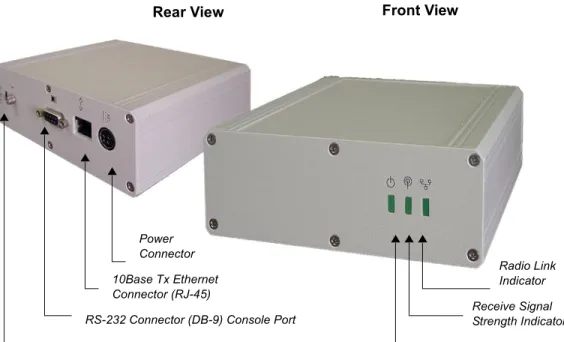
Figure 8 NCL1170 Connectors and Indicators
2. Use an RS-232 straight-through cable to connect a terminal to the DB9 console port.
NOTE: You can use any ASCII terminal, such as a single-function terminal or a computer running terminal-emulation software to communicate with the NCL1170 through its console port. Use this port for configuring and debugging only; you do not have to remain connected through it during normal operation. Figure 9 illustrates the pin-out for the console port.
Receive Signal Strength Indicator
Radio Link Indicator
Power ON Indicator
Front View Rear View
Power Connector 10Base Tx Ethernet Connector (RJ-45)
RS-232 Connector (DB-9) Console Port Antenna Connector (WaveRider custom SMA)
3 Installing the NCL1170
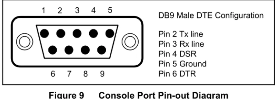
Figure 9 Console Port Pin-out Diagram
3. If you are using a terminal-emulation package, such as HyperTerminal, start the application.
4. In the terminal-emulation application, select the communications port that you are using to connect to the NCL1170.
5. Configure the application using the following settings:
• 9600 bps
• 8 data bits
• no parity
• 1 stop bit
• no flow control
6. Plug the NCL1170 into a 110 or 220 V AC power source using the custom power cord provided with the unit.
NOTE: When disengaging and removing the NCL1170 power cord, carefully slide back the locking collar around its DC connector.
DB9 Male DTE Configuration Pin 2 Tx line
Pin 3 Rx line Pin 4 DSR Pin 5 Ground Pin 6 DTR 9
8
6 7
4 5 3 2 1
3 Installing the NCL1170
APCD–NC006–A 14
3.2 Initializing the NCL1170
As the unit powers-up, and the initialization sequence begins, progress messages are displayed on the terminal screen. When initialization is complete, you will receive a message indicating that the system is operational, followed by the PASSWORD: prompt. The factory default password for the NCL1170 is a <blank field>, although WaveRider recommends that you assign an unique password to each NCL1170 in your network.
If the NCL1170 default password <blank field> is acceptable, Enter. Otherwise,
To change the password of your NCL1170, follow the instructions in Changing the NCL1170 Password, on page 15.
To specify a system name for your NCL1170, follow the instructions in Setting the NCL1170 System Name, on page 16.
To reload the default settings of an NCL1170 already configured for use elsewhere in your network, follow the instructions is Resetting an NCL1170 to Factory Defaults, on page 16. If the NCL1170 is a factory-configured unit, you can omit this step.
For each of these procedures, you must be connected to the NCL1170 and logged into the device.
3 Installing the NCL1170
3.2.1 Changing the NCL1170 Password
Use this procedure if you want to request a password before users log on.
For maximum security, we recommend that you set a unique password for each unit in your network, and record all passwords on the Configuration Data Record for the group. Refer to Appendix E for a copy of the NCL1170 Network Group Configuration Data Record.
To change the password of the NCL1170
1. At the NCL1170> prompt, type <system password>.
2. At the Enter Current Password: prompt, type the old password.
3. At the Enter New Password: prompt, type the new password.
TIP: Use a maximum of sixteen (16) alphanumeric characters. Passwords are case-sensitive. For example,
“abc” is not the same as “aBc”.
4. At the Verify password: prompt, type the new password again.
The system will display a message that your password has been successfully changed.
5. Type <write> or <save> to save the settings to memory.
Your session to change the password may be similar to the following example session:
NCL1170> system password
Enter Current Password: *******
Enter New Password: ****
Verify password: ****
System password has been changed.
NCL1170>
CAUTION: Remember to record the password in your Data Configuration Record.
Unlocking the NCL1170 can be a complicated process. If you forget your NCL1170 password, contact WaveRider Product Assistance.
3 Installing the NCL1170
APCD–NC006–A 16
3.2.2 Setting the NCL1170 System Name
Use this procedure if you want to uniquely identify your system by either name or location.
To change the system name of the NCL1170
1. At the NCL1170> prompt, type <system name your_system_name> to name the NCL1170 in your system.
TIP: We recommend that you use a system name that uniquely identifies each unit, based on its location, its purpose, or a combination of both. For example, a system name, Station_firehall identifies the NCL1170 configured as a Station and located at the firehall.
Example: To change the system name from NCL1170 to Station_firehall would look like this:
NCL1170> system name Station_firehall System name changed to: Station_firehall
Station_firehall>
2. Type <write> or <save> to save the settings to memory.
NOTE: In this User Manual, the command-line prompt will always be shown as NCL1170>.
3.2.3 Resetting an NCL1170 to Factory Defaults
Use this procedure if the NCL1170 has already been configured for use elsewhere in your network and you need to restore its factory settings.
To reset the factory defaults of the NCL1170
1. Connect the NCL1170 to a terminal or terminal-emulation software and at the NCL1170> prompt, type <write erase> to reset the unit to its factory-default settings.
2. Type <reboot> for the unit to recognize the factory-default settings.
4 Configuring the NCL1170
This section describes the steps required to configure the NCL1170 as either a bridge or router, including the options available for routing and system monitoring. You can configure the NCL1170 two ways:
• Console Port command line interface (CLI)
• WaveRider Configuration Utility (GUI)
If you choose to configure the NCL1170 via console port CLI, before proceeding, familiarize yourself with the command definitions and keyboard syntax (See NCL1170 Command-Line Syntax on page 57.), plus command and help keyboard shortcuts (See Table 7 on page 58.).
NOTE: The following section describes the procedures for configuring the NCL1170 via CLI. To download the WaveRider Configuration Utility from our web site, contact Product Assistance to request a password, then visit: <http://www.waverider.com/techsupport/>
to download the software.
The procedures for configuring the NCL1170 via command-line interface are divided into two categories:
• Radio configuration—see Setting the Radio Configuration on page 18
• IP configuration—see Setting the IP Configuration on page 19 You can also configure the NCL1170 for the following options:
• Routing Information Protocol (RIP)—see Setting RIP Configuration on page 20
• Dynamic Host Control Protocol (DHCP) Relay—see Setting the DHCP Relay Configuration on page 22
• Simple Network Management Protocol (SNMP)—see Setting the SNMP Configuration on page 22
4 Configuring the NCL1170
18 APCD–NC006–A
4.1 Setting the Radio Configuration
Before setting the radio configuration parameters, ensure that the NCL1170 has been connected to a terminal and initialized as described in Connecting the NCL1170, on page 12, and that the password has been set as described in Changing the NCL1170 Password, on page 15.
WARNING!
Antennas and associated transmission cable must be installed by qualified personnel. Failure to terminate the antenna port correctly can permanently damage the NCL1170. WaveRider assumes no liability for failure to adhere to this recommendation or to recognized general safety precautions.
1. Determine the radio channel for the network. See Appendix C for a list of operating frequencies.
2. At the NCL1170> prompt, type <radio channel channel> to set the radio channel for the NCL1170, where channel is the number of the network radio channel on which the unit will operate.
3. Determine the unit IDs for the Master and Stations for this NCL1170 network group.
The unit ID is a unique number, from 1 to 16383, that is used to identify the NCL1170 within the network group.
4. At the NCL1170> prompt, type <radio unitid unit_id> to set the NCL1170 unit ID.
5. To set the NCL1170 as a Master, type <radio type master>. To set the NCL1170 as a Station, type <radio type station>.
If the NCL1170 is a Master, add the unit IDs for the Stations that are configured for this network group. At the NCL1170> prompt, type <radio station add
station_unitid> where station_unitid is the unit ID for a Station.
NOTE: To remove a Station from the Remote Station List, type <radio station del station_unitid> where station_unitid is the unit ID for the Station you want removed.
6. Repeat step for each Station that you want to add to the Remote Station List for the Master NCL1170. A maximum of 20 Stations can be added to one Master.
7. If the NCL1170 is a Station, add the Master unit ID for the network group. At the NCL1170> prompt, type <radio masterID master_unitid> where master_unitid is the unit ID for Master NCL1170 in the network group.
TIP: To display a list of Stations associated with a specific NCL1170 Master, type <radio station> at the NCL1170> prompt.
4 Configuring the NCL1170
8. At the NCL1170> prompt, type <write> to save the settings to memory.
4.2 Setting the IP Configuration
Check that the NCL1170 is has been connected to a terminal and initialized as described in Connecting the NCL1170, on page 12 and you have changed the password as described in Changing the NCL1170 Password, on page 15.
Before configuring IP options, complete the radio configuration as described in Setting the Radio Configuration, on page 18.
1. At the NCL1170> prompt, type <ip address ethernet aaa.bbb.ccc.ddd nn>
to set the IP address for the Ethernet interface. aaa.bbb.ccc.ddd is the IP address of the NCL1170 and nn is the number of bits in the subnet mask (for example, 24 represents a subnet mask of 255.255.255.0).
2. At the NCL1170> prompt, type <mode bridging> or <mode routing> to set the forwarding mode.
If you are setting the NCL1170 to operate in bridging mode, go directly to Step 3.
If setting the NCL1170 to routing mode, type <ip address radio
remote_unit_id aaa.bbb.ccc.ddd eee.fff.ggg.hhh> to set the IP address for the radio interface to the remote unit. aaa.bbb.ccc.ddd is the IP address for the local unit and eee.fff.ggg.hhh is the IP address for the remote unit.
NOTE: If you change the radio IP address for a Station at a later time, remember to update the Master with the new Station IP address.
If you change the radio IP address for a Master at a later time, remember to update each Station in the Remote Station List with the new remote IP address for the Master.
3. For a Master unit, repeat step 2 for every Station in the group. For a Station unit, you only need to enter the remote unit IP address for the Master.
4. Optionally, you can add up to 256 static routes for the NCL1170. At the NCL1170>
prompt, type <ip route add aaa.bbb.ccc.ddd eee.fff.ggg.hhh subnet_mask> where aaa.bbb.ccc.ddd is the IP address for the destination network, eee.fff.ggg.hhh is the IP address for the gateway, and subnet_mask is specified in the number of bits.
5. If the mode is routing and the NCL1170 is a Master, type <ip route add
station_ethernet_subnet station_radio_ip_address subnet_mask> to route the Master subnet traffic to the Master.
4 Configuring the NCL1170
20 APCD–NC006–A
8. At the NCL1170> prompt, type <write> to save the settings to memory.
9. When done configuring the NCL1170, disconnect the terminal from the NCL1170.
4.3 Configuration Options
For added performance, flexibility, and convenience, the NCL1170 offers users the following configuration options:
Routing Mode
• Routing Information Protocol (RIP)—see Setting RIP Configuration on page 20
• Dynamic Host Control Protocol (DHCP) Relay—see Setting the DHCP Relay Configuration on page 22
System Monitoring
• Simple Network Management Protocol (SNMP)—see Setting the SNMP Configuration on page 22
• Domain Name Service (DNS) Resolver—see Setting the DNS Resolver Configuration on page 23
After completing these procedures, it is important to confirm that the configuration is correct before deploying the NCL1170 in the field. Refer to Chapter 5, Testing and Deployment, on page 35.
Two example configuration diagrams and sessions are provided in Examples of Bridging and Routing Configurations, on page 24: one for a point-to-multipoint bridging network, and the second for a point-to-multipoint routing network.
4.3.1 Setting RIP Configuration
When the NCL1170 is operating in Routing Mode, you can optionally enable the Routing Information Protocol (RIP) feature. RIP is a protocol that runs between two routers (for example, two NCL1170s) or servers to allow exchange information about routes. When RIP is enabled in routing mode, the NCL1170 can be configured to “advertise” default routes and static routes, as well as interface routes.
In bridging mode, enabling RIP has no effect.
4 Configuring the NCL1170
The NCL1170 supports both RIP versions 1 and 2. You can set RIP version 2 to either broadcast, compatible, or multicast modes.
CAUTION: RIP version 1 exchanges the minimal amount of information necessary for an NCL1170 to route packets through a network, and does not consider subnetting, which is required to determine the best route. If the designated RIP route is a network route, RIP version 1 will interpret the network mask and subnet mask as the same, which may not always be correct. To avoid possible problems, we recommend NCL1170 users install RIP version 2, which exhanges explicit subnet and ‘next- hop’ information for each route.
1. At the NCL1170> prompt, type <ip rip enable> to enable RIP as the routing mode.
2. To transmit the route information in packets, type <ip rip active>. If RIP is set to quiet, it receives and processes RIP packets, but it does not transmit them.
3. Type <ip rip version> to display the current version of RIP.
4. If RIP is version 1, it is broadcast only. To change RIP routing to support version 2, type <ip rip version 2>.
5. If you set RIP to version 2, you can additionally specify how RIP handles packets.
6. To enable RIP to advertise the default route, if one exists, in the advertisement, type
<ip rip default>.
To set RIP to advertise static routes, as well as all other RIP information, type
<ip rip update>. To send all route information except static route data, type <ip
To do this.... Type...
Disable RIP Routing <ip rip disable>
Enable RIP routing. <ip rip enable>
Send version 2 advertisements as broadcast. <ip rip broadcast>
Send version 2 advertisements to RIP version 2 multicast addresses. This is generally more efficient than broadcast.
<ip rip multicast>
4 Configuring the NCL1170
22 APCD–NC006–A
4.3.2 Setting the DHCP Relay Configuration
When the NCL1170 is in routing mode, you can optionally enable Dynamic Host Control Protocol (DHCP) relay which makes the NCL1170 aware of the protocol for DHCP traffic and forwards the responses to the designated DHCP server.
NOTE: When the NCL1170 is operating in bridging mode, DHCP Relay is transparent, and therefore, not an available option.
You can specify up to five DHCP servers in the NCL1170 configuration.
1. At the NCL1170> prompt, type <dhcp mode relay> to enable DHCP Relay in the device.
2. To add a DHCP server, type <dhcp relay add ip_address> where
ip_address is the IP Address for the DHCP Server available for the NCL1170 to forward and receive DHCP traffic.
3. At the NCL1170> prompt, type <save> to transfer the settings to memory.
NOTE: To remove a DHCP server, type <dhcp relay delete ip_address>. To disable DHCP Relay, type <dhcp mode none>.
4.3.3 Setting the SNMP Configuration
Simple Network Management Protocol (SNMP) enables a network management station to remotely monitor and control network devices incorporating an SNMP agent.
SNMP allows you to look at SNMP variables using READ communities, and to set SNMP variables using WRITE communities. Communities are optional on the NCL1170, but it can support a maximum of five communities. An NCL1170 is factory-configured with two communities, a READ community called “public” and a WRITE community called “private.”
SNMP also provides a mechanism called trap, which notifies a network management station that a significant event has taken place. A significant event can be an interface going down or coming up, a unit performing a cold or warm start, or an authentication failure. Refer to RFC 1157 for details.
Associated with SNMP are Management Information Bases (MIBs). These specify a collection of management information available from the agent. This information can be controlled and monitored from a network management station.
The NCL1170 implements SNMPv2c and includes a number of standard SNMP MIBs:
• RFC1157 (MIB-Il)
• RFC1493 (bridging)
• an NCL1170-specific MIB
WaveRider MIBs can be downloaded from the technical support page at www.waverider.com.
The following procedure describes how to configure standard SNMP communities for read/
write access to the NCL1170 SNMP agent and to specify a server IP address to which trap messages are sent.
4 Configuring the NCL1170
1. At the NCL1170> prompt, type <snmp> to display the current SNMP settings for the NCL1170.
2. To add a new community, type <snmp community add community
READ|WRITE> where community is the name of the community and READ|WRITE is the community type. You can have a maximum of five communities.
3. If a community is not set up the way you want it, delete it by typing
<snmp community del community READ|WRITE> where community is the name of the community and READ|WRITE is the community type.
4. At the NCL1170> prompt, type <snmp location location> to change the geographical location of the NCL1170.
5. Type <snmp contact contact> to change the contact name for the NCL1170. The contact can be a name and phone number, a URL, or an email address.
6. To add a trap server to the NCL1170 configuration, type <snmp trap add
aaa.bbb.ccc.ddd community> where aaa.bbb.ccc.ddd is the IP address of the trap server and community is the name of the community on the trap server.
7. To delete a trap server from the NCL1170 configuration, type <snmp trap del aaa.bbb.ccc.ddd community> where aaa.bbb.ccc.ddd is the IP address of the trap server and community is the name of the community on the trap server.
8. At the NCL1170> prompt, type <save> to transfer the settings to memory.
4.3.4 Setting the DNS Resolver Configuration
The NCL1170 implements Domain Name Server/Service (DNS) resolver software. Once configured, you can use host names instead of IP addresses when you make a Telnet connection from the NCL1170 console to other IP hosts on the network, or when you issue ping or traceroute commands to test connectivity.
Adding DNS lists is optional on the NCL1170, but you can configure the NCL1170 to use a maximum of five DNS servers. An NCL1170 is factory-configured with no DNS servers listed.
You can also configure the NCL1170 to include a domain name for your local IP network.
The following procedure describes how to configure the NCL1170 to implement DNS resolver software and configure the NCL1170 domain name. Setting the DNS resolver configuration is optional.
1. At the NCL1170> prompt, type <ip dns> to display the current DNS setup used by the NCL1170.
2. To add a DNS Server, type <ip dns server add aaa.bbb.ccc.ddd> where aaa.bbb.ccc.ddd is the IP address of the DNS Server.
3. To delete a DNS Server, type <ip dns server del where
4 Configuring the NCL1170
24 APCD–NC006–A
4.4 Examples of Bridging and Routing Configurations
The following diagrams show typical point-to-multipoint bridging and routing network
topologies, plus the corresponding command-line entries required to configure the devices in the network.
In a point-to-multipoint network configuration, each NCL1170 must be configured to operate as either a bridge or router. You cannot mix operational modes.
4.4.1 Point-to-Multipoint Bridging Network
Figure 10 shows a configuration of a typical point-to-multipoint bridging network.
Figure 10 Example of Point-to-Multipoint Bridging Network
In Figure 10, unit A has been configured as the Master of the system with remote units B, C, and D configured as Stations. Units B, C, and D unit IDs have been manually added to the Master (unit A) Remote Station List. The Master unit ID on each Station is set to the unit ID for unit A. If a unit is not in the Master Remote Station List, or does not have the Master unit ID set, it will not be able to join the network.
The following example session shows how to configure the Master NCL1170 for the bridging network shown in Figure 10.
Ethernet NCL1155
C
Ethernet NCL1155
B Ethernet
NCL1155 D
Ethernet Radio NCL1155
A
Type: Station
Unit ID: 103
Radio Channel: 1
Mode: Bridging
IP Address - Ethernet: 10.0.2.103
Master ID: 1001
Type: Station
Unit ID: 102
Radio Channel: 1
Mode: Bridging
IP Address - Ethernet: 10.0.2.102
Master ID: 1001
Type: Station
Unit ID: 101
Radio Channel: 1
Mode: Bridging
IP Address - Ethernet: 10.0.2.101
Master ID: 1001
Type: Master
Unit ID: 1001
Radio Channel: 1
Mode: Bridging
IP Address - Ethernet: 10.0.2.44 Remote Station List: 101
102 103
4 Configuring the NCL1170
NCL1170>
NCL1170> radio channel 1 Radio channel changed to: 1 NCL1170> radio unitid 1001 Unit ID changed to: 1001 NCL1170> radio type master Radio type changed to: Master NCL1170> radio station add 101 Station added.
NCL1170> radio station add 102 Station added.
NCL1170> radio station add 103 Station added.
NCL1170> radio RADIO CONFIGURATION:
Radio type : Master Wireless ID : 1001
Speed : 11Mbs
Channel : 1
Regulatory Domain : FCC/IC Frequency : 2.412 GHz
Interframe spacing: 32 (281.6 micro seconds) Hardware address : 00:90:27:CA:62:A3
Network Card IRQ : 5 NIC Base Address : 0x0d0000 Remote Stations : 101
: 102 : 103
NCL1170> ip address ethernet 10.0.2.44 16 IP addresses:
Ethernet: 10.0.2.44/16 NCL1170> mode bridging Forwarding mode: Bridging NCL1170> ip
Forwarding Mode: BRIDGING Addresses:
Ethernet: 10.0.2.44/16
Routing: IP Routing (Static Only) Routing Table:
Destination Mask Gateway Flags Protocol Interface ---
10.0.0.0 16 10.0.2.44 UC Local eeE0
10.0.2.44 0 10.0.2.44 UHL ICMP lo0
127.0.0.1 0 127.0.0.1 UH Local lo0
---
Sets the radio channel
Sets the NCL1170 unit ID Sets the NCL1170 type to Mas Adds a station to the Master Remote Station List
Displays the radio configuration information
Changes the local Ethernet IP address Sets the mode to bridging Displays the IP configuration information
4 Configuring the NCL1170
26 APCD–NC006–A
The following example session shows how to configure Station B in Figure 10 to join the network. To configure the remaining Stations, use the same procedure, replacing the unit ID and IP address for each with the appropriate information for that Station.
NCL1170>
NCL1170> radio channel 1 Radio channel changed to: 1 NCL1170> radio unitid 101 Unit ID changed to: 101 NCL1170> radio type station Radio type changed to: Station NCL1170> radio masterid 1001 Master Id changed to: 1001
NCL1170> ip address ethernet 10.0.2.101 16 IP addresses:
Ethernet: 10.0.2.101/16 NCL1170> mode bridging Forwarding mode: Bridging NCL1170> radio
RADIO CONFIGURATION:
Radio type : Station Wireless ID : 101
Speed : 11Mbs
Channel : 1
Regulatory Domain : FCC/IC Frequency : 2.412 GHz
Interframe spacing: 32 (281.6 micro seconds) Hardware address : 00:90:27:CA:62:A3
Network Card IRQ : 5 NIC Base Address : 0x0d0000 Master ID : 1001 NCL1170> ip
Forwarding Mode: BRIDGING Addresses:
Ethernet: 10.0.2.101/16
Routing: IP Routing (Static Only) Routing Table:
Destination Mask Gateway Flags Protocol Interface ---
10.0.0.0 16 10.0.2.101 UC Local eeE0
10.0.2.101 0 10.0.2.101 UHL ICMP lo0
127.0.0.1 0 127.0.0.1 UH Local lo0
--- DNS Domain Name:
DNS Servers:
No DNS servers defined.
NCL1170> write
Sets the NCL1170 type to Station
Identifies the unit ID of the Master for this
4 Configuring the NCL1170
4.4.2 Point-to-Multipoint Routing Network
Figure 11 shows a configuration of a typical point-to-multipoint routing network.
Figure 11 Example of Point-to-Multipoint Routing Network
The following example session shows how to configure the Master NCL1170 for the routing network shown in Figure 11.
NCL1170>
NCL1170> ip address ethernet 14.0.2.44 16 IP addresses:
Ethernet: 14.0.2.44/16 NCL1170> mode routing Forwarding mode: IP Routing NCL1170> dhcp
DHCP Disabled
NCL1170> dhcp mode relay DHCP Relay Enabled
NCL1170> dhcp relay add 10.0.1.44 DHCP Servers/Relay Agents:
10.0.1.44
NCL1170> radio channel 1
Ethernet NCL1155
C
Ethernet NCL1155
B Ethernet
NCL1155 D
Ethernet Radio NCL1155
A
Type: Station
Unit ID: 103
Radio Channel: 1
Mode: Routing
IP Address - Ethernet: 13.0.2.103 - Radio: 10.0.2.103
Master ID: 1001
Type: Station
Unit ID: 102
Radio Channel: 1
Mode: Routing
IP Address - Ethernet: 12.0.2.102 - Radio: 10.0.2.102
Master ID: 1001
Type: Station
Unit ID: 101
Radio Channel: 1
Mode: Routing
IP Address - Ethernet: 11.0.2.101 - Radio: 10.0.2.101
Master ID: 1001
Type: Master
Unit ID: 1001
Radio Channel: 1
Mode: Routing
IP Address - Ethernet: 14.0.2.44 - Radio: 10.0.2.44 Remote Station List: 101
102 103
Sets the mode to routing DHCP Relay is disabled by default
Enable DHCP Relay Add a DHCP Server to the DHCP Relay table
4 Configuring the NCL1170
28 APCD–NC006–A
Station added.
NCL1170> radio station add 102 Station added.
NCL1170> radio station add 103 Station added.
NCL1170> ip
Forwarding Mode: IP ROUTING Addresses:
Ethernet: 14.0.2.44/16
Radio: 101, 10.0.2.44 p-t-p ? 102, 10.0.2.44 p-t-p ? 103, 10.0.2.44 p-t-p ? Routing: IP Routing (Static Only) Routing Table:
Destination Mask Gateway Flags Protocol Interface
---
14.0.2.44 0 14.0.2.44 UHL ICMP lo0
14.0.0.0 16 14.0.2.44 UC Local eeE0
127.0.0.1 0 127.0.0.1 UH Local lo0
--- DNS Domain Name:
DNS Servers:
No DNS servers defined.
NCL1170> radio RADIO CONFIGURATION:
Radio type : Master Wireless ID : 1001
Speed : 11Mbs
Channel : 1
Regulatory Domain : FCC/IC Frequency : 2.412 GHz
Interframe spacing: 32 (281.6 micro seconds) Hardware address : 00:90:27:CA:62:A3
Network Card IRQ : 5 NIC Base Address : 0x0d0000 Remote Stations : 101
: 102 : 103
NCL1170> ip address radio 101 10.0.2.44 10.0.2.101 IP addresses:
Ethernet: 14.0.2.44/16
Radio: 101, 10.0.2.44 p-t-p 10.0.2.101 102, 10.0.2.44 p-t-p ?
103, 10.0.2.44 p-t-p ?
NCL1170> ip address radio 102 10.0.2.44 10.0.2.102 IP addresses:
Ethernet: 14.0.2.44/16
Radio: 101, 10.0.2.44 p-t-p 10.0.2.101 102, 10.0.2.44 p-t-p 10.0.2.102 103, 10.0.2.44 p-t-p ?
NCL1170> ip address radio 103 10.0.2.44 10.0.2.103 IP addresses:
Ethernet: 14.0.2.44/16
Radio: 101, 10.0.2.44 p-t-p 10.0.2.101 102, 10.0.2.44 p-t-p 10.0.2.102 103, 10.0.2.44 p-t-p 10.0.2.103
Displays the IP configuration
The ? means that the IP address for the remote uni in the routing network has not been set
Sets the radio IP address for the route to station B (unit ID 101)
Sets the radio IP address for the route to station C (unit ID 102)
Sets the radio IP address for the route to station D (unit ID 103)
4 Configuring the NCL1170
NCL1170> ip route add 11.0.0.0 10.0.2.101 16 Routing Table:
Destination Mask Gateway Flags Protocol Interface ---
14.0.2.44 0 14.0.2.44 UHL ICMP lo0
10.0.2.101 0 10.0.2.44 UHC Local mdr1
10.0.2.102 0 10.0.2.44 UHC Local mdr2
10.0.2.103 0 10.0.2.44 UHC Local mdr3
14.0.0.0 16 14.0.2.44 UC Local eeE0
11.0.0.0 16 10.0.2.101 UC Static mdr1
127.0.0.1 0 127.0.0.1 UH Local lo0
--- NCL1170> ip route add 12.0.0.0 10.0.2.102 16
Routing Table:
Destination Mask Gateway Flags Protocol Interface ---
14.0.2.44 0 14.0.2.44 UHL ICMP lo0
10.0.2.101 0 10.0.2.44 UHC Local mdr1
10.0.2.102 0 10.0.2.44 UHC Local mdr2
10.0.2.103 0 10.0.2.44 UHC Local mdr3
14.0.0.0