Predicting the binding site of ligands in proteins, starting with the apo-protein, is one of the challenges in the field of virtual ligand screening. Goddard gave me the opportunity to work closely with members of the Scripps Research Institute.
Virtual Ligand Screening
Introduction to Molecular Docking and Virtual Ligand Screening
Calculated energies are used to identify the role of physical and chemical interactions in protein function and behavior. A concern with these methods is the dependence on the size, composition, and generalizability of the training set used to derive the weights (Tame, 1999).
Interaction of E. coli Outer Membrane Protein A with Sugars on the Receptors of the Brain Microvascular Endothelial Cells
2 ABSTRACT
We used a hierarchy of coarse grain docking method with molecular dynamics (MD) to predict the binding sites and energies for interactions of GlcNAcβ1,4GlcNAc and other sugars with OmpA. This theoretical study elucidates the interaction sites of chitobiose with OmpA and the binding site predictions can be tested by mutation studies or by invasion assays.
Introduction
11 B. Fine grain MD search
Binding Energy Calculation: The binding energies of the 20x5 annealed structures for each ligand in each of the 12 binding regions were calculated. The best conformation from this pool was selected by binding energy for each of the 12 docking regions.
13 Cellobiose
Results and Discussion
We thus find a good correlation between the binding energies of the ligands to OmpA and the measurements of the experimental invasion assay. The correlation between the calculated binding energies and the results of the invasion assay suggests that the binding of OmpA is a necessary step in pathogenesis.
Conclusions
A second plausible mechanism is that two sugar moieties from two sites glycosylated by Ecgp interact with both OmpA sites at the same time.
Acknowledgements
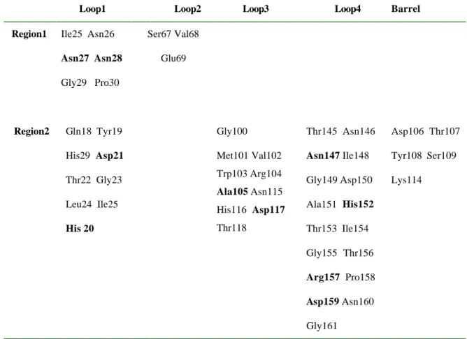
Residues listed here are within 5 Å of chitobiose in regions 1 and 2. Residues in bold are within 3 Å of chitobiose and have critical contacts with chitobiose.
Mechanism for Antibody Catalysis of the Oxidation of Water by Singlet Dioxygen
METHODS
We then selected the top 20 conformations from DOCK in each region and subjected each ligand to MD annealing to further optimize the conformation in the local binding pocket allowing for both the ligand and the binding cavity (residues with one atom within 5Å of the binding ligand) to move. A dielectric constant of 80.37 was used for the solvent domain in the SGB calculation and 2.0 for the protein interior.
Summary of results from QM calculations and plausible mechanisms
In addition to binding energies, we also examined the population density of good binding structures in each region. Depending on the products from steps f and g, this QM-based mechanism leads to a net reaction of.
Here we find the two clusters (P1 and P2 shown in Figure III-2b) that contain most of the highest binding structures. Both P1 and P2 are located in the hydrophobic region between the barrel interface of the variable and constant domains. Once again we used the HierDock protocol to perform an unbiased search for binding sites in all regions of the TCR.
We found that HOOOH monomers and dimers accumulate at the interface of the heavy and light chain (sites I1–I3) of the TCR. These results support the conclusion that it is the IGKD interface created by the arrangement of the immunoglobulin domains that is required for the stabilization of the intermediates.
DISCUSSION
This suggests that the unique feature responsible for catalysis is the IGKD (present only for antibodies and TCR), not the Greek key fold (which is present in all immunoglobulins, including β2-microglobulin and other proteins).
Nature of binding site for HOOOH monomer and dime r
Thus, the first step of our QM mechanism involves two leads in a dimer-like structure, as in Figure III-4a or 4b, with one of the leads acting as a catalyst in this step. A closer look at the interface of the light and heavy chains of all antibodies shows that the bottom of the channel or barrel is capped by polar amino acids. Instead, these intermediates would go to the side of the barrel at the light-heavy chain interface, as shown in Figure 3a.
For Fab, our studies of the binding of HOOOH and its dimer and H2O2 suggest the model that the IGKD motif is essential for the production of H2O2 from singlet oxygen. Since the antibody Fc structure has one such IGKD interface compared to two in the Fab structure, this suggests that the efficiency of HOOH production in the Fc should be half that of the Fab.
To determine whether these glutamines play a role in capping the products of 1O2 chemistry, it would be interesting to investigate systems in which the glutamines are mutated to hydrophobic residues. Because the Fc structure of antibodies has one such IGKD interface compared to two in the Fab structure, this suggests that the efficiency of HOOH production in Fc should be half that of Fab. Indeed, Wentworth and Lerner[16] have shown that Fc structures have half the efficiency of Fab structures. This HOOOH could react with a second 1O2 or it could migrate to the I3 site where it could react with a second HOOOH.
Such a destructive role is consistent with the observation that 1O2 is produced in processes involved with the macrophage involving antigen-bound antibody.
Conclusions
We speculate that the conversion of 1O2 to HOOOH and/or HOOH might provide a protective function against singlet oxygen (which can attack dienes and other molecules in cells). Alternatively, these reactive intermediates may react with the antigen and help make the protein recognized by the antibody more susceptible to attack by other enzymes in the macrophage. These results suggest a number of experimental tests and provide guidance on how to construct biomimetic nanoscale systems for HOOH (or HOOOH) production.
In particular, the results explain the observed molecularity of 2.0 for the number of HOOH produced per 1O2.
Acknowledgments
We also thank Xueyong Zhu, Nicholas Larsen, and Ian Wilson for access to their 1.2 Å structure for the chimeric Fab antibody prior to publication. The MSC facilities used in the studies were funded by NSF-MRI, DURIP (ARO and ONR) and the Beckman Institute. These constructions were used in the dock studies. a) Clustering sites for linking HOOOH dimers.
Regions I1-I3 are at the interface of the inter Greek key domain (IGKD) unique to antibodies and TCRs. b) H2O2 binding sites. The P1-P2 regions are at the interface of the inter-Greek key domain (IGKD) unique to antibodies and TCRs.
V HVL
These sites are at the interface of the VH and VL in a region containing well-ordered crystallographic waters (shown with half bonds). The inset shows a schematic antibody structure with a yellow circle to indicate the magnified region. b) The structure in (a) is rotated 90º about the horizontal axis to show the hydrophobic channel bounded by Gln38 from VL and Gln39 from VH. The HOOOH can stay at I1 (or I2), but it can go to I3, which does not have crystallographic water.
This HOOOH can react directly with a second 1O2 or with HOOOH from a previous reaction to form the HOOOH dimer. The HOOOH dimer can rearrange through a series of steps to form HOOH, which can go to the P1 or P2 sites (there are no crystallographic waters at these sites).
Selectivity And Specificity Of Substrate Binding In Methionyl-tRNA Synthetase
2 Abstract
In the second step, the activated amino acid is transferred to the 3β-ribose of the conserved CCA-3. Conformational change in aaRS induced by binding and aminoacyl-adenylate complex formation. We used the HierDock computational protocol for the first prediction of the methionine binding site in MetRS in apo-MetRS (crystal) [17].
Binding energy calculations of methionine analogs were performed in the conformation that activates the protein, i.e. We have studied the specificity of MetRS for methionine in the first two steps of the binding process.
25 References
Zhang, D., et al., Structure-based design of mutant Methanococcus jannaschii tyrosyl-tRNA synthetase for incorporation of O-methyl-L-tyrosine. Datta, D., et al., An engineered phenylalanyl tRNA synthetase variant allows efficient in vivo incorporation of aryl ketone functionality into proteins. Mechulam, Y., et al., Crystal structure of Escherichia coli methionyl-tRNA synthetase highlights species-specific features.
Serre, L., et al., How Methionyl-tRNA Synthetase Creates Its Amino Acid Recognition Pocket Upon Binding of l-Methionine. Fourmy, D., et al., Identification of residues involved in methionine binding by Escherichia coli methionyl-tRNA synthetase.
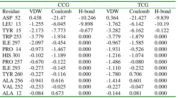
LEU 13 TYR 15
Met leu glu gln val asp his ile gly cys ala ser phe asn trp tyr pro thr arg.
TYR 260
TRP 305
HIS 301
PHE 300
Tyr 260
Protein Design
Chapter 5
Introduction to Protein design
7 References
A Designed Apoplastocyanin Variant that Shows Reversible Folding
Abstract
Chapter 7
Designing Protein β -Sheet Surfaces by Z-Score Optimization
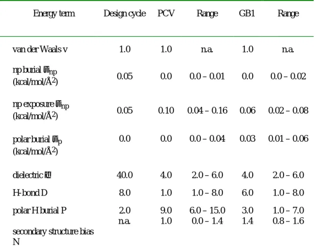
For GB1, the maximum Z-score is 2.6, i.e. the wild-type sequence is assigned an energy lower than 99.5% of all possible sequences. The modeled side chain configurations are shown in Figure VII-3b along with those of the wild-type crystal structures (Gallagher et al., 1994). The Z-score was calculated using 4000 random sequences to determine the energy distribution of the potential function on the structure, resulting in an uncertainty in the Z-score of .
The actual distribution of energies of various subsets of the actual protein GB1, using the potential function derived from the protein design cycle (Table 1). a) The core (only the 2.5% lowest-energy ranges are shown), b) the β-sheet surface. Views of the eight designed positions on the β-sheet surface of GB1 and PCV. a) the crystallographically determined wild-type GB1 side chain orientations.. b) the orientations modeled using the Z-score derived potential function on GB1. c) the crystallographically determined PCV wild-type side chain orientations. d) the orientations modeled using the Z-score derived potential function on PCV.
Evaluation of the Energetic Contribution of an Ionic Network to Beta-Sheet Stability
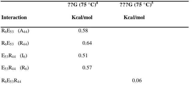
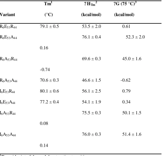
To test the effect of an ionic triad in the context of the β-sheet surface, we have evaluated the energetic contribution of a three-residue triad constructed on the β-sheet surface of GB1. The network consists of Arg 6, Glu 53 and Arg 44, residues which lie on three adjacent strands of the β-sheet surface (Figure 1a). Double mutant cycle analysis was used to isolate the interaction energy of the triad (Horovitz & Fersht, 1990).
In this three-residue thermodynamic cycle, the interaction energy of the ionic network is calculated as in equation 1. 4??G (75 °C) interaction energy (calculated at 75 °C) of the ion pair in the presence of the residue given in parentheses.
ABSTRACT