I certify that this project report entitled “CHARACTERIZATION OF A HIGH-TEMPERATURE SOLAR THERMAL SYSTEM USING A NON-IMAGING FOCUSING HELIOSTAT” was prepared by LOH YING ZHE and has met the required submission standards in partial fulfillment of the requirements for the award of MSc in Electrical Engineering at Tunku Abdul Rahman University. The copyright of this report belongs to the author under the terms of the Copyright Act 1987 as set out in the Intellectual Property Policy of Universiti Tunku Abdul Rahman. The use of any material contained in or derived from this report must always be duly acknowledged.
First and foremost I would like to thank everyone who contributed to the successful completion of this project. Chong Kok Keong for providing the necessary materials and resources with invaluable advice, guidance and his immense patience during the development of the research. The optimal simulated result within the shortest time period is investigated and the factors affecting the efficiency of the NIFH, such as the circumsolar ratio (CSR) and the slope error (SE), are studied and the results show that with an increase in CSR and SE the spillage loss increases, the heliostat efficiency decreased and caused a bias in the flux distribution profile of the NIFH.
1 INTRODUCTION
Problem Statement
The major challenge of the solar thermal system that includes the focusing heliostat is the astigmatism aberration that accompanies the change of angle of incidence during sun tracking. The astigmatism effect causes enlarged image area and reduced intensity which lowers the quality of a solar thermal system. The work is to perform simulation and optimization for the best performance with NIFH will be performed.
Characterizing the results is equally important to identify the variable that can be controlled to improve the research.
Research Objectives The objectives of the research is to
The mathematics of sun tracking, which is the azimuth-elevation tracking formula, remained the same and was used for decades until the operating principle of NIFH, the spinning elevation, also called target-aligned tracking, was first proposed by Ries and Zaibel in 1995 without segmented facet and ability to focus. In order for the solar oven to achieve a higher solar concentration ratio of more than 20,000 suns, a conventional solar oven system typically requires three stages: a primary heliostat as a sun tracker to reflect sunlight, a secondary parabolic concentrator to moderately concentrate the sunlight, and a tertiary composite parabolic concentrator to further enhance the focused sunlight. 10-20 years ago a solar oven with an uncorrected focusing heliostat and a parabola was tested in Germany or Israel or other countries with rather poor results due to aberration of the tracking mirror.
For example, conventional solar furnaces that have been built are the furnace of Arizona State College in the USA (Kevane, 1957), Solar Energy Research Institute (SERI) High-Flux Solar Furnace (Lewandowki, 1991), the furnace of the Government Institute for Industrial Research in Japan (Hisada et al., 1957), large solar furnace in Odeillo, France with 1000 kW (Trombe and Le Phat Vinh, 1973), large solar furnace of the Academy of Sciences of Uzbekistan with 1000 kW (Abdurakhamanov et al., 1998 ), the furnace of Paul Scherrer Institute (PSI), of 25–40 kW (Schubnell et al., 1991), the furnace of CIEMAT, in Plataforma Solar de Almerı´a, Spain with 45 kW (Fernandez-Reche et al. ., 2006), and the furnace of DLR, in Cologne, Germany, of 20 kW (Neumann and Groer, 1996). In this context, the size of the secondary concentrator is very dependent on how well the primary focus can be performed by the NIFH heliostat. For cost savings and reduction of complications in the control system, a good approach to full astigmatic aberration correction can be made with the application of a new spin-height tracking method that preserves the vertical and horizontal directions of the heliostat frame to always align be with the tangential and sagittal planes respectively.
With the new optical configuration, dynamic correction of astigmatism due to the variation of angle of incidence can be greatly simplified by just moving element mirrors in a group fashion so that those mirrors of the same row or column can share the same mechanical actuator. With the focusing task partially implemented by NIFH heliostat, the secondary concentrator can be significantly reduced by at least 25 times in area, and thus ultra-high concentration can be cost-effectively achieved with only a two-stage system. In practice, Lim and Li (2009) successfully demonstrated the new solar furnace using a 5 m × 5 m prototype NIFH and a much smaller spherical furnace.
In addition, purification of metallurgical silicon to solar-grade silicon is achieved using the new solar furnace, and it is proposed to extract the boron using the photochemical effect method (Chen et al. Simulation codes for traditional azimuth elevation heliostat have been developed by several research groups which can be found in HELIOS (Vittitoe and Biggs, 1976), CIRCE (Ratzel et al., 1986), MIRVAL (Leary and Hankins, 1979), new code by Wei et al (2010), etc. .
3 METHODOLOGY
Calculation for Optimal Mirror and Solar Disc Resolution
The target size, Ts, is divided into pixels, which is 201 pixels in the study. The rMR is the resolution of the mirror, while rSD is the resolution of the solar disk. In the simulation, each mirror element of a heliostat of size w is represented by the number of reflective points, nMR, and the number of subbeams per aperture radius, nSD.
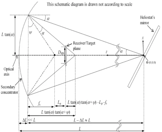
First, the correlation between rMR or rSD and rTR can be calculated with the following expression. The DSD is the diameter of the receiver plane in cm and with reference to Figure 1, the DSD. Whereα is the solar disk's half angle of 4.65 mrad and the 𝛹𝛹 is can be calculated as 𝛹𝛹 = tan−1( 𝑓𝑓𝑇𝑇.
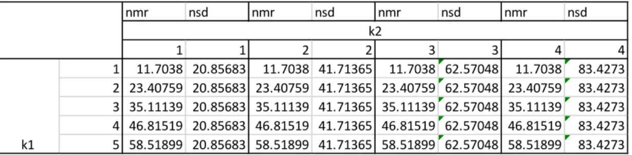
The mirror resolution is increased for nMR by a factor of k1, while the resolution of the solar disk is increased for nSD by a factor of k2, as shown in Table 4. The calculated resolution in Table 4 is then rounded up to match the odd value input requirement for nMR and even value for nSD.
Number of Ray
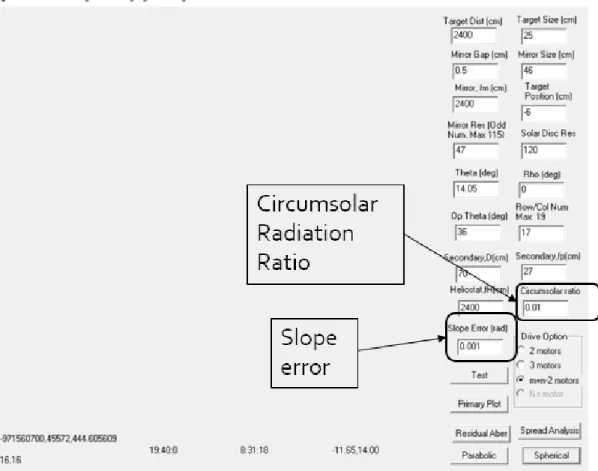
Slope Error
Circumsolar Ratio
Spillage
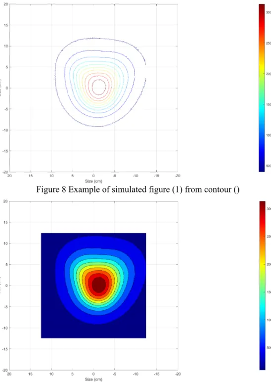
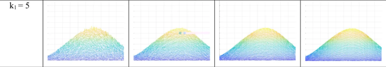
The command lines plot the flux distribution in figure (1), where 'contour()' creates a contour plot containing only isolines of data, while 'contourf()' filled in the contour plot containing isolines of data. The following command lines keep the number 1 and calculate the total concentration in the quadratic form with increasing dimension by integrating the concentration from 1 cm x 1 cm up to 25 cm x 25 cm. The mesh function creates a 3-D surface in terms of the concentration heights from the data plotted in Figure (2).
Plot()' creates a 2-D line plot of the concentration in Y versus the corresponding values in X on Figure(3).
Number of Ray and Corresponding Simulation Time
Comparison between Mirror Resolution and Solar Disc Resolution on Flux Distribution
From Tables 9 and 10, the radius/disk increases along with nSD, while it remains constant for fixed nSD with increasing nMR. The comparison in Table 8 shows that the higher mirror resolution improves the shape of the flux profile most at the center point because the number of rays per disc is constant throughout the increasing resolution of the solar disc. On the other hand, the number of rays per disc increases with a higher value of the solar disc resolution resulting in smaller spikes and increases the smoothness of the flux.
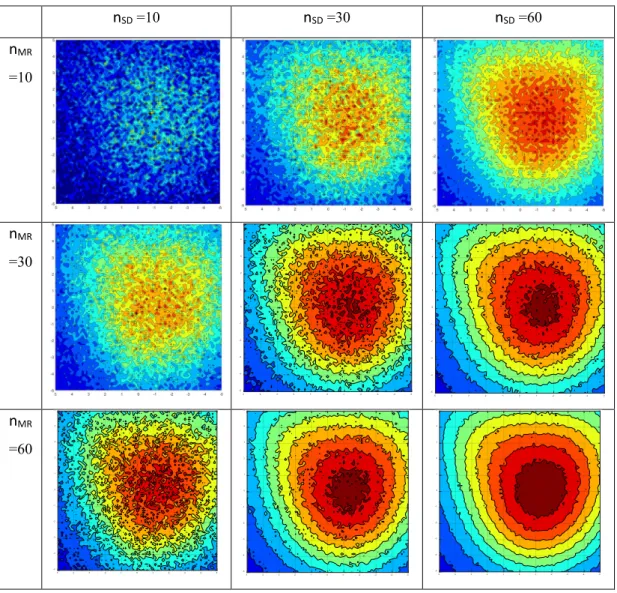
The higher k1 and k2 (high resolution), the smoother the current distribution profile and the more constant and accurate the concentration becomes. At low k1 and k2 (low resolution), the maximum solar concentration ratio is high due to spikes and deviations throughout the flux profile. As shown in Figure 14, the simulation time in the function of k1 and k2 increases considerably with higher resolution, so the optimal resolution value with relatively good results can be sufficient for the simulation work.
High-accuracy simulation results of the solar flux distribution can be generated with a high number of mirror resolutions and a high solar disk resolution. Therefore, the highlighted cell in the table is recommended for the optimal resolution for accurate and mature patterns, with the shortest simulation time.
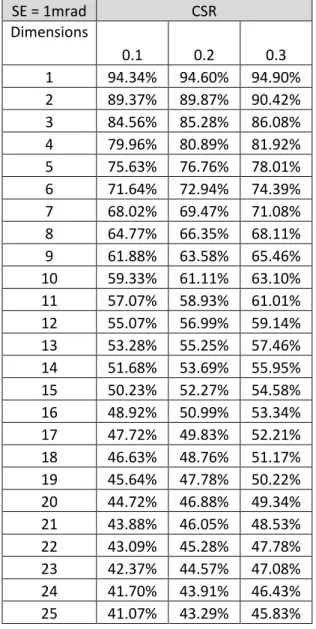
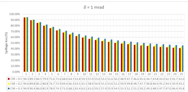
Slope Error and Circumsolar Ratio Effects on Spillage loss of NIFH Figure 15, Figure 16, and Figure 17 show the spillage loss versus receiver size from
This work studies the characteristics of the high temperature solar furnace using NIFH with NIFH simulator and MATLAB. When examining the relationship between the number of beams and the simulation time, the simulation time increased linearly with the number of beams. The number of rays determines the resolution of the output flux distribution, therefore higher number of rays, higher simulation time with more accurate result.
Therefore, optimal resolution factor of k1 factor to mirror resolution and k2 factor to solar disk resolution is studied to obtain a reasonable and accurate result in the shortest time. In addition, the factor affecting the flux distribution profile for the heliostat, such as circumsolar ratio and inclination error, are studied. The circumsolar ratio and tilt error show attenuation of the flux shape resulting in reduced heliostat performance with spill loss as high as 40% for 25cm receiver size.
Recommendations for Future Work
Report of the first prototype non-imaging focused heliostat and its application to high temperature solar furnace. Report on the second prototype non-imaging focused heliostat and its application in food technology. Optimization of imageless focusing heliostat in dynamic astigmatism correction for a wide range of incident angles.
Study of the range of motion for two different sun tracking methods in heliostat field application. Cost-effective solar furnace system using fixed-geometry non-imaging focusing heliostat and secondary parabolic concentrator. Verification of optical modeling of sun shape and surface inclination error for concentrating solar power systems.
Performance optimization of dense array concentrating photovoltaic system considering the effects of circular solar radiation and tilt error. A detailed study on the effects of sun shape and incidence angle on the optical performance of parabolic solar collectors.