The Influence of Temperature on Mechanical Properties and Fiber Damage
by
Muhd. Aizat Nazmi Bin Yusoff
Dissertation submitted in partial fulfilment of the requirements for the
Bachelor ofEngineering (Hons) (Mechanical Engineering)
JANUARY 2009
Universiti Teknologi PETRONAS
Bandar Seri Iskandar 31750 Tronoh
Perak Darul Ridzuan
Approved by,
CERTIFICATION OF APPROVAL
The Influence ofTemperature on Mechanical Properties and Fiber Damage
by
Muhd. Aizat Nazmi Bin Yusoff
A project dissertation submitted to the Mechanical Engineering Programme
Universiti Teknologi PETRONAS in partial fulfilment ofthe requirement for the
BACHELOR OF ENGINEERING (Hons) (MECHANICAL ENGINEERING)
ftl
(Assoc. Prof Dr. Puteri Sri Melor MegatYusoff)
Dr Puteri Sri Melor Bt Megat Yusoff
Associate Professor
Mechanical Engineering Department Universiti Teknologi PETRONAS
UNIVERSITI TEKNOLOGI PETRONAS TRONOH, PERAK
January 2009
CERTIFICATION OF ORIGINALITY
This is to certify that I am responsible for the work submitted in this project, that the original work is my own except as specified in the references and acknowledgements, and that the original work contained herein have not been undertaken or done by unspecified sources or
persons.
r
£
MUHD AIZAT NAZMI BIN YUSOFF
ACKNOWLEDGEMENTS
The author wishes to take the opportunity to express his utmost gratitude to the individual that have taken the time and effort to assist the author in completing the project. Without the cooperation of these individuals, no doubt the author would have laced some minor complications through out the course.
First and foremost the author's utmost gratitude goes to the author's supervisor, Assoc. Prof Dr. Puteri Sri Melor Megat Yusoff. Without her guidance and patience, the author would not be succeeded to complete the project. To the Final Year Project Coordinator, Assoc. Prof. Dr Puteri Sri MelorMegatYusoff(FYP I) and Prof Dr. VijayR Raghavan (FYPII) for providing him with all the initial information requiredto begin the project.
In addition, for the technician post graduate student in Mechanical Engineering Department and Chemical Engineering Department, thank you for assisting the author in completing his project. To all individuals that has helped the author in any way, but whose name is not mentioned here, the authorthankful for the effortand appreciate it.
ABSTRACT
The purpose of this project is to study the influence of processing temperature on
mechanical properties and extent of fiber damage of the empty fruit bunch (EFB) - high
density polyethylene (HDPE) composites during compounding and processing. The
samples produced from the injection molding were subjected to tensile and flexural teststo correlate the effect of various processing temperatures with the mechanical properties
of the composites. Fibers of 3-5 mm in length were compounded with HDPE using an
extruder to form the raw material of the composites. The resulting compound was
transferred to the injection molding to obtain the specimens required for the tensile and
flexural tests. The injection molding temperature was varied from 170°C, 175°C, 180°C,
185°C to 190°C. Finally, fiber damage characterization was conducted by dissolving the
HDPE matrix using xylene and measuring the length of the remaining fiber after
extrusion process, injection molding, tensile and flexural tests.TABLE OF CONTENTS
ABSTRACT .
TABLE OF CONTENTS . LIST OF FIGURES.
LIST OF TABLES .
LIST OF ABBREVIATIONS
CHAPTER 1:
CHAPTER 2:
CHAPTER 3:
CHAPTER 4:
INTRODUCTION
1.1 Background of Study .
1.2 Problem Statement
1.3 Objectives and Scope of Study
THEORY AND LITERATURE REVIEW 2.1 Natural Fibers.
2.1.1 Cell Wall Structure of Natural Fiber
2.1.2 Mechanical Properties of Natural Fiber 2.2 Polyethylene .
2.3 Xylene.
2.4 Natural Fiber Composites 2.5 Processing Technologies
2.5.1 Extrusion
2.5.2 Injection Molding
2.6 Literature Review
MATERIALS AND METHODS 3.1 Materials
3.1.1 Oil Palm EFB.
3.1.2 HDPE .
3.2 EFB Preparation 3.3 Composite Preparation
3.4 Tensile & Flexural Test Sample Preparation 3.5 Mechanical Testing .
3.5.1 Tensile Test . 3.5.2 Flexural Test .
3.6 Fiber Damage Measurement
RESULTS AND DISCUSSION .
4.1 Effects on Mechanical Properties 4.2 Fiber Damage Characterization
l
ii-iii iv
v
vi
1 1 4 5
6 6 6 7 8 9 10 11 11 12 13
16 16 16 16 17 17 18 18 18 20 21
23 23 27
4.2.1 Fiber Damage during Extrusion . 27 4.2.2 Fiber Damage during Injection Molding 29 4.3 Morphological Studies on Fractured Surface
of the Composites 30
CHAPTER 5: CONCLUSION AND RECOMMENDATION . 33
REFERENCES 34
APPENDICES 37
m
LIST OF FIGURES
Figure 2-1 Classification of natural fibers derived from plants 7
Figure 2-2 Structure of natural fibers 8
Figure 2-3 The repeat unit of polyethylene 8
Figure 2-4 Three aromatic hydrocarbon isomers of xylene 10
Figure 2-5 Photograph of an extruder machine 12
Figure 2-6 Photograph of an injection molding machine 13
Figure 3-1 Photographs of (a) oil palm tree and 16
(b) oil palm empty fruit bunch
Figure 3-2 Photograph of fibers with specific average length 17 Figure 3-3 Dog-bone shaped specimens of HDPE composite 18 Figure 3-4 The sample configuration of the tensile test 19
Figure 3-5 Dimension of the EFB-HDPE Specimens 19
Figure 3-6 The sample configuration ofthe flexural test 20 Figure 3-7 Extraction process of EFB-HDPE composites (extrusion) 21
Figure 3-8 Extraction process of EFB-HDPE composites (injection molding) 22
Figure 4.1 Tensile strength of EFB-HDPE composites 24 Figure 4.2 Tensile modulus of EFB-HDPE composites 24 Figure 4-3 Flexural strength of EFB-HDPE composites 25 Figure 4-4 Flexural modulusof EFB-HDPE composites 26 Figure 4-5 Modulus of rupture of EFB-HDPE composites 27 Figure 4-6 Distribution of fiber length before and after extrusion 28Figure 4-7 Distribution of fiber length afterinjection molding at temperature
170°C. 29
Figure 4-8 Distribution of fiber length afterinjection molding at temperature
190°C. 29
Figure 4-9 SEM micrograph of the tensile-fractured surface of high temperature
of the EFB-HDPE composites 31
Figure 4-10 SEM micrograph of the tensile-fractured surface of lowtemperature
of the EFB-HDPE composites 31
IV
TABLES
Table 2-1 Physical and mechanical properties of selected natural fibers 9 Table 4-1 Percentage of Fibers Damaged at Varying Temperatures 30
APPENDIX
Appendix 1 Gantt Chart 37
LIST OF ABBREVIATIONS
EFB Empty fruit bunch
FFB Fresh fruit bunch
HDPE High density polyethylene
OPEFB Oil palm empty fruit bunch
PE Polyethylene
PP Polypropylene
SEM Scanning electron microscopy
UV Ultraviolet
VI
CHAPTER 1
INTRODUCTION
1. PROJECT BACKGROUND
1.1 Background of Study
Oil palm or Elais guineensis was first introduced in Malaysia in 1870. However, the first generation of reinforced plastic industries only began in 1940 with the introduction glass fibers as reinforcement [1]. Owing to its commercial importance, the botanical and cultivation aspects of oil palm have been extensively studied. Recently, much attention has been channeled toward finding suitable applications for oil palm industry by-products. In the light of the scarcity of timber and different environmental issues, various types of by-products have been studied to see whether they can serve as replacements for timber or reduce environmental problems.
Oil palm fruit is attached on fresh fruit bunch. The bunch that left after the removal of the fruit is called empty fruit bunch (EFB). Oil palm empty fruit bunch is one of the Hgnocellulosic materials that have been used in the production of potassium fertilizer as well as in mulching [2]. Mesocarp fibers and oil palm frond are the example of EFB wastes. These fibrous wastes can create major environmental problems when simply left on the plantation fields. However, some
of them are utilized as boiler feedstock in the oil mill which are also left to
degrade as soil fertilizer in the field, while almost of these wastes are not utilized.
The environmental problems will significantly reduced because of utilization of
these biomasses wastes and at the same time it will increase the economical
benefit. Other than that, these fibers gained a lot of advantages such as low cost, low density, sustainable and biodegradable. As a result, natural fibers are gaining ever increasing attention as reinforcement in polymer based composites.
Composite is a combination of two or more materials. In general, composite consists of a matrix material like polymers and ceramics and a discrete phase like fibers and particles. The matrix material acts as a load transferring medium
between the fibers. There are several natural fibers that can be used to reinforce thermoplastic polymer composite. Currently, several natural fibers such as flax, hemp, jute and kenaf are being utilized commercially as reinforcement materials for automotive applications. Recently, automobile industries have started using natural fiber reinforced composites for various interior and exterior applications such as door trim panels, seat backs, floor panels and speaker covers [3].
Natural fibers composites are also utilized as alternate building materials and furniture, especially as replacement of wood-filled plastics [4]. Thermosetting based composites usually have better mechanical performance over thermoplastic composites. It is due to the presence of polar groups in thermosets, which promotes better interaction with natural fibers [5]. Even though they have many benefits, natural fibers also have several disadvantages. For example, these natural fiber composites are sensitive towards water and relatively poor thermal stability [6].
This factor actually will cause the mechanical properties of the natural fibers in the composites to degrade. Because of this factor, several physical methods have been developed in order to improve fiber-matrix adhesion of natural fiber composites. The purpose of the physical methods is to change the structural and surface properties of the fiber and at the same time, improve the adhesion between
the fiber and the matrix.
On the other hand, a wide-ranging study is required before these fibrous wastes could be employed as filler in polymer composites successfully. Besides, research needs to be conducted in order to characterize the behavior of oil palm fibers and their properties when incorporated into polymers. For this project, empty fruit bunch (EFB) is chosen as filler in the polymer composites due to the fact that EFB is the major biomass waste and EFB possess better mechanical properties.
High density polyethylene (HDPE) is prepared from ethylene by a catalytic process. The absence of branching results in a more closely packed structure with a higher density and somewhat higher chemical resistance than low density polyethylene (LDPE). HDPE is also stronger and more opaque and it can withstand higher temperatures of 120°C for short periods or 110°C continuously [7].
The incorporation of fibers into polymer will increase the composites strength and modulus if there is a significant stress transfer from the matrix to the fibers. This can only be attained if the fiber length is greater than the critical fiber length where the critical fiber length is the minimum length necessary for effective transmission of stress from the matrix to those fibers. If the length of the fibers in a composite is shorter than the critical length, failure in fiber-matrix interface can occur even at low stresses due to debonding, resulting in a weak composite.
Whereas, if the fiber length is greater than the critical length, the load transfer is optimal, resulting in a strong composite [8].
However, it is possible to decrease this critical length and yet maintain high composite strength by improving the interfacial bonds between the fiber and the matrix [9]. It should be noted that during compounding and injection molding, fibers are damaged resulting in shorter fiber lengths. The amount of fiber damaged depends on the fiber content, viscosity of the polymer melt and the melt- flow velocity. The average fiber length remaining after processing is an important factor affecting the strength of a composite.
1.2 Problem Statement
Nowadays, natural fiber composites are becoming popular as an alternative to glass or carbon fiber reinforced composites due to their promising properties and environmental friendly nature. However, there are some drawbacks posed by these materials, especially in plastic composites, such as thermal instability at high temperatures and poor mechanical properties. Therefore, a systemic investigation is necessary to fully describe the behavior oil palm fibers and their composites.
Fiber length is an important parameter that needs to be considered in order to achieve significant reinforcement in polymer composites. Longer fiber in the composites generally leads to improved mechanical properties of the composites.
The fiber content should be limited to a certain level, with the length of 3.0-5.0 mm in order to allow the melted material to flow. However, the length of these fibers can be shortened during injection molding and extrusion.
It should be noted that during compounding and injection molding, fibers are damaged resulting in shorter fiber lengths. The amount of fiber attrition depends on the fiber content, viscosity of the polymer melt and the melt-flow velocity. The average fiber length remaining after processing is an important factor affecting the strength of a composite. The strength of these composites will be decreased as a result of fiber attrition during processing. Normally, most of these fibers will be shortened during extrusion. This is because, these fibers will go through the single or twin rotating screws inside the heated barrel of the extruder and injection molding which slowly shorten the length of the fibers due to the rotating screw speed which could be up to 120 rpm.
Further experimental study need to be conducted in order to characterize the fiber length changes during processing at high temperatures. This is because the fibers may further be shortened as the processing temperature increases. Once the
behaviors of the fibers are known, fiber damage can be controlled in order to improve the composites mechanical properties including the tensile and flexural properties.
13 Objective and Scope of Study
As the reinforcement effect of fibers in a composite is influenced by the fiber length, it is the objective of the current study to investigate the effect of temperature on the mechanical properties and fiber damage as the injection molding temperature was varied. The processing technologies involved were extruder and injection molding. During extrusion, the temperature was set as 170°C in zone 1 and 2,180°C in zone 3 to 7,200°C for flange and 210°C at the die.
Throughout the compounding, these temperatures were kept constant with initial fiber length of 3.0-5.0 mm. The injection molding temperatures were varied from 170°C, 175°C, 180°C, 185°C to 190°C. The amounts of fibers that have been damaged during processing were investigated at every temperature. In addition, the effects of varying temperature on mechanical properties were analyzed.
CHAPTER 2
THEORY / LITERATURE REVIEW
2.1 Natural Fiber
Natural fibers become popular due to their low-cost, low density and sustainable characteristics. Although there are some difficulties in dealing with natural fibers especially due to their fibrous structure, they still possess high strength and stiffness [10]. In fiber-reinforced composites, the fibers serve as reinforcement by giving strength and stiffriess to the structure while the plastic matrix serves as the adhesive to hold the fibers in place so that suitable structural components can be
made.
Natural fibers can be broadly classified into two main categories which are non-
wood and wood fibers. Wood fibers can be obtained from softwood and
hardwood, whereas non-wood fibers are obtained from mono or dicotyledonous plants. Currently several non-wood fibers (i.e. hemp, kenaf, flax, and sisal) are being utilized commercially in bio-composites in combination with polyethylene for automotive applications. The classification of natural fibers derived from plants is represented schematically in Figure 2-1.
2.1.1 Cell Wall Structure of Natural Fiber
The cell wall structure of natural fiber is a composite. It consists of hollow cellulose fibrils held together by lignin and pectin in hemicellulose matrix. Each fibril has a complex, layered structure, consisting of a thin primary wall encircling a thick secondary wall as shown in Figure 2-2. The secondary wall is made up of
three layers and the thick middle layer determines the mechanical properties of the fiber. The middle layer consists of series of helically wound cellular microfibrils formed from the long chain cellulose molecules [11,12],
Reinforcing natural/bio-fibers
Non-wood natural/bio-fibers
Bast
Examples:
Kenaf, flax, hemp
Leaf
Seed/
fruit
Examples:
Cotton, coir Examples:
Henequen, sisal
Wood fibers
Examples:
Soft and hard woods
Recycled wood
fibers
Examples:
Newspaper/ma gazine fibers
Figure 2-1 Classification of natural fibers derived from plants [12],
2.1.2 Mechanical Properties of Natural Fiber
The mechanical properties of natural fiber are dependent on the cellulose content in the fiber, the degree of polymerization of the cellulose and the angle of the microfibrils. The microfibrillar angle is the angle between the fiber axis and the microfibril. Fibers with higher cellulose content, higher degree of polymerization and a smaller microfibrillar angle exhibit higher tensile strength and modulus. The physical and mechanical properties of selected natural fibers are shown in Table
2-1.
Secondary wall S3
Helically arranged crystalline microfibrils of cellulose
Amorphous region mainly consisting of lignin
and hemicellulose
Lumen
Secondary wall S2 Spiral angle
Secondary wallS1
Primary wall
Disorderly arranged
crystalline cellulose microfibrils networks
Figure 2-2 Structure of natural fibers [13].
2.2 Polyethylene (PE)
Polyethylene is a polymer consisting of long chains of the monomer ethylene (IUPAC name ethene). The recommended scientific name polyethene is systematically derived from the scientific name of the monomer. In certain
circumstances it is useful to use a structure-based nomenclature. In such cases
IUPAC recommends poly (methylene) [14]. The difference is due to the opening up of the monomer's double bond upon polymerization.
The ethene molecule also known by its common name ethylene, CH2=CH2 and Figure 2-3 shows the repeat unit of polyethylene:
Figure 2-3 The repeat unit of polyethylene [14].
In this study, HDPE will be used as the matrix. This polymer is highly crystalline and tough can be formed by most processing methods.
Table 2-1 Physical and mechanical properties of selected natural fibers [12].
Young's Elongation Density Diameter Tensile Strength Modulus at Break
Fiber (g/cm3) (fim) (Mpa) (Gpa) (%)
Flax 1.5 40-600 345-1500 27.6 2.7-3.2
Hemp 1.47 25-500 690 70 1.6
Jute 1.3-1.49 25-200 393-800 13-26.5 1.16-1.5
Kenaf 930 53 1.6
Ramie 1.55 400-938 61.4-128 1.2-3.8
Sisal 1.45 50-200 468-700 9.4-22 3.0-7.0
Abaca 430-760
Oil palm
EFB 0.7-1.55 150-500 248 3.2 25
Oil palm
mesocarp 80 0.5 17
Cotton 1.5-1.6 13-38 287-800 5.5-12.6 7.0-8.0
Coir 1.15-1.46 100-460 131-220 4.0-6.0 15-40
2.3 Xylene
The term xylene or xylol refers to a mixture of three aromatic hydrocarbon
isomers which is used as a solvent in the printing, rubber, and leather industries.Generally, xylene is a clear, colorless, sweet-smelling liquid that is very flammable. Like other solvents, xylene is also used as an inhalant drug for its
intoxicating properties.Xylene is a generic term for a group of three aromatic hydrocarbon isomers,
essentially benzene derivatives, which encompasses ortho-, meta-, and para-
isomers of dimethyl benzene as shown in Figure 2-4. The o-, m- and p-
designations specify to which carbon atoms (of the benzene ring) the two methyl
groups are attached. Counting the carbon atoms from one of the ring carbons
bonded to a methyl group, and counting towards the second ring carbon bonded to
a methyl group, the o- isomer has the IUPAC name of 1,2-dimethylbenzene, the
m~ isomer has the IUPAC name of 1,3-dimethylbenzene, and the/?- isomer hasthe IUPAC name of 1,4-dimethylbenzene. Solvent grade xylene usually contains a small percentage of ethylbenzene as a contaminant [15].
1,2-dimethylbenzene 1,3-dimethylbenzene 1,4-dimethylbenzene (xylene)ortfto- (xylene)mefa- (xytene)para-
Figure 2-4 Three aromatic hydrocarbon isomers of xylene [15].
2.4 Natural Fiber Composites
Generally, a composite consists of a matrix material like polymers and ceramics
and a discrete phase like fibers and particles. The matrix material acts as a loadtransferring medium between the fibers. In order to form composites, fibers can be combined with thermosets. Thermosetting materials have advantages and disadvantages over thermoplastic. Natural fiber composites based on thermoset matrix usually have good mechanical performance. It is due to the presence of
polar groups in thermosets which promotes better interaction with the naturalfibers.
Thermoplastics composites are produced by two key methods which are extrusion and injection molding. It involves compounding of the fiber and the matrix at the matrix melting point in internal mixer or extruder. Then, it follows by a shaping operation which is injection molding. In order to produce good quality composites, it requires certain viscosity to assure the flow ability of the fiber and melted
polymerduring processing.10
However, the mechanical properties of composites still depend on the individual components and their interfacial compatibility. The strength of composites is determined by the strength of the fiber and by the ability of the matrix to transmit stress to the fiber. Transmission of stress to the fiber is affected by fiber orientation, fiber geometry (e.g. length and diameter) and interfacial bonding between the fiber and the matrix. A good interfacial bond is required for effective matrix-fiber stress transfer whereby maximum utilization of the fiber strength in the composite is achieved [16].
2.5 Composites Processing Technology
Extrusion, compression and injection molding are the methods that will be used to produce thermoplastics composites. Processing of natural fiber composites based on thermoplastic matrix involves compounding of the fiber and polyethylene in extruder, followed by a shaping operation such as injection molding.
2.5.1 Extrusion
In the extrusion of plastics, raw thermoplastic material in the form of small beads (often called resin in the industry) is gravity fed from a top mounted hopper into the barrel of the extruder. Additives such as colorants and UV inhibitors (in either liquid or pellet form) are often used and can be mixed into the resin prior to mixing in the extruder.
The material enters the extruder barrel through the feed throat (an opening near the rear of the barrel) and comes into contact with the screw. The rotating screw which is normally turning up to 120 rpm forces the plastic beads forward into the barrel which is heated to the desired melt temperature of the molten plastic [17].
In most processes, a heating profile is set for the barrel in which three or more independent PID controlled heater zones gradually increase the temperature of the barrel from the rear (where the plastic enters) to the front. This allows the plastic
11
beads to melt gradually as they are pushed through the barrel and lowers the risk of overheating which may cause degradation in the polymer.
The materials will be melted along the path of the extruder screw as shown in
Figure 2-5, although in some cases the feed material is already in the melt form and the extruder screw needs only to convey it. The melting of the polymer is aided by heaters that are tightly encapsulated outside the barrel diameter and are separated into several zones. These zones can be set at different temperatures to
suit to a particular process involved.Die
/
Breaker plate
Feedpipe
/
Barrel
X
Feedthroat
Screw
— — " — — r — i f
Screw drive motor
Figure 2-5 Photograph of an extruder machine [17].
2.5.2 Injection Molding
Injection molding is a manufacturing process to produce parts from both thermoplastic and thermosetting plastic materials. Molten plastic is injected at high pressure into a mold, which is the inverse ofthe product's shape. Photograph
of an injection molding machine is shown in Figure 2-6.
12
Molded Part
Molten Plastic
Raw Plastic
Figure 2-6 Photograph of an injection molding machine [17].
It will start with the plasticizing process and followed by injection process of the plastic melt from the barrel into the closed mold. The subsequent step involves cooling of the thermoplastic molded part in the mold until it is sufficiently rigid to be ejected. The final step is the release of the molded-part, which involves opening the mold, ejecting the part and closing the mold [18].
2.6 Literature Review
Weak interfacial compatibility between the matrix and the fiber results in reduced efficiency of stress transfer from the matrix to the reinforcement component. As highlighted, the quality of interfacial bonding is determined by several factors, such as the nature of Hgnocellulosic and thermoplastic materials as well as their compositions, the fiber aspect ratio including the length of the fibers, the types of incorporation procedures and the processing conditions employed.
Folkes M.J. et al. [19] reported that fiber breakage is a significant problem during extrusion process and the design of the screw is of some importance, deep flights
13
being required. Twin screw extruders are often preferred and the fibers are sometimes fed into the barrel part way along so that they enter directly into melt:
this is found to reduce fiber damage.
In most of the common short fiber thermoplastic molding materials the original fiber length is around 3-5 mm but few fibers survive mixing and molding undamaged, with most fibers present in molding measuring fractions of a millimetre. At the end of the experiment, he found that more than 20% of the fibers damaged after go through the boiling process of the composites in the pure xylene solution at 190°C. The final length of the fibers were measured by image analysis that used automatic two point measuring mode and may serve as the best method as it can generate more accurate and statistically representative data.
Mandell JF et al. [20] reported the molding materials are normally supplied in the form of granules with the fibers already mixed into the polymer, usually at a concentration within the range 10-40% by weight, which corresponds very roughly to 5-20% by volume, depending on the densities of the polymer and the
fibers.
The granules are normally cylindrical with length 3-5 mm and ~3 mm diameter, and the fibers may span their length or, more usually, are much shorter. The fiber length becomes significantly degraded during processing but the residual length still provides useful reinforcement. The fiber attrition occurred when undergo the processing technology such as compounding and injection molding
While for tensile strength, it showed the strength of the EFB composites with different thermoplastic matrix depended on the type of matrix used. The impact strength for various composites will decrease as the filler loading was increased.
The impact strength of EFB-HDPE composite was significantly higher than the others. This maybe attributed to the ability of HDPE matrix to undergo plastic
14
deformation in the form of crazing and shear yielding during the crack propagation process.
H. Ismail et al. [21] in his research investigated the effects of shortening on stretch-induced force enhancement in single skeletal muscle fibers. The experiments were performed with single muscle fibers (^mm length) extruded with polypropylene (PP) as matrix. After compounding process, the granules of muscle fibers-PP were soaked into benzene solution at 130°C for 4 hours. Then,
10 single muscle fibers were taken and performed under scanning electron microscopy (SEM) to investigate the fiber damaged. As a result, 10-30% of the fiber length becomes significantly shortened during the compounding process.
By using the same type of matrix, Mohanty et al. [22] used another approach in order to investigate the mechanical properties of rice straw fiber-PP when the temperatures varied. Increase in temperature led to increased moduli and decreased tensile and impact strength. While X-ray diffraction experiments showed that introducing fiber to PP matrix did not change characteristic peak position, but the fiber increased crystalline thickness of PP system. The study showed that rice straw fibers can work well with PP as reinforcing filler. Future work will deal with effect of coupling treatments of the straw fibers in single phase or commingled plastics composite systems.
15
CHAPTER 3
MATERIALS AND METHODS
3.1 MATERIALS
3.1.1 Oil Palm Empty Fruit Bunch (EFB)
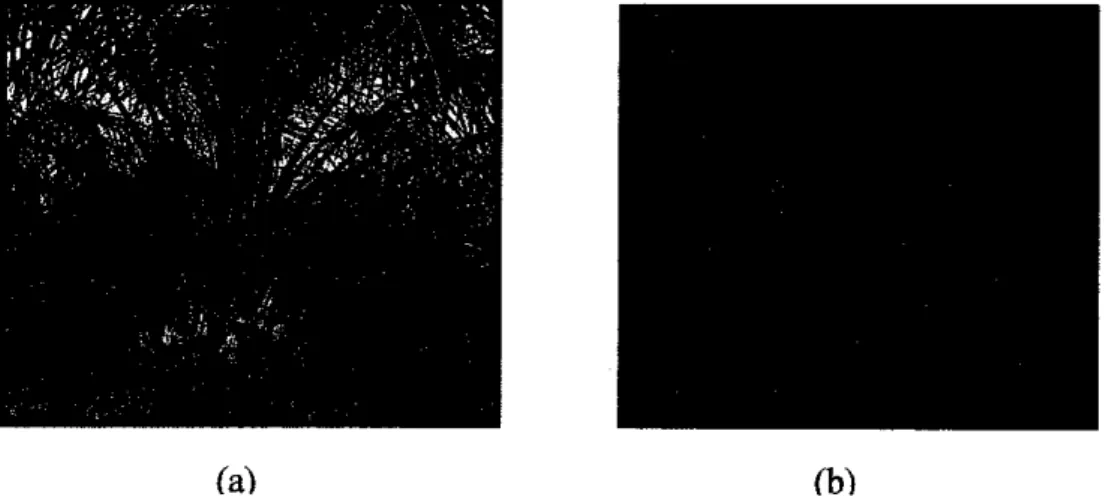
EFB is one of the by product obtained from palm oil industry. It consists of a bunch of fibers in which palm fruit are embedded [23]. The fiber is extracted by retting process of the EFB. Average weight of EFB fiber is about 400-500 g per bunch. Photograph of oil palm tree and EFB are shown in Figure 3-1(a) and (b).
In this project, EFB was obtained in the form of pulverized fiber.
(a) (b)
Figure 3-1 Photographs of (a) oil palm tree and (b) oil palm empty fruit bunch.
3.1.2 High Density Polyethylene (HDPE)
HDPE used was from Titan Petchem (M) Sdn. Bhd. with melting point of 130°C
and a density of0.96 g/cm3.
16
3.2 EFB Preparation
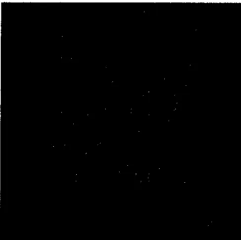
EFB fibers were washed with hot water to remove contaminants. Then, the dried
fibers were cut into the average length of 5 mm and were passed through 500 um
sieve to obtain a uniform sized of filler. The photographof specific average lengthof fibers is shown in Figure 3-2. To remove the moisture content, EFB was put in
an oven at 80-90°C for 24 hours.
Figure 3-2 Photograph of fibers with specific average length.
3.3 Composite Preparation
The specimens were prepared in two steps: compounding and tensile test sample preparation using injection molding. The EFB content of the HDPE composites
was 20%wt. The mixing of EFB and HDPE was carried out using the twin screw extruder. Therefore, the extruder temperatures were set at 170°C (zone 1 and 2), 180°C (zone 3 to 7), 200°C for flange and 210°C for the die temperature. For extrusion process, the temperatures will not be varied. Then, these compounds were extrudedthrough a single rod die, and subsequently cooled in water bath and then palletized.17
3.4 Tensile and Flexural Test Sample Preparation
The compounded granules from the extrusion process were then transferred to the Tat Ming ME20 injection molding machine. For this process, the temperature was varied. Once the cooling and water pump indicator is in the 'ON' position, the required temperature was programmed. The temperature was varied from 170°C to 175°C, 180°C, 185°C and 190°C. Next, after the required temperature was achieved as displayed on the screen, the hopper was filled with the compounded granules containing 20%wt of the EFB fibers.
The injection molding process started with the plasticizing process, which involved heating and melting the plastics in the cylindrical barrel, followed by injecting of the plastic melt from the barrel into the closed mold. Finally, the molded-part will be released, which involved opening the mold and ejecting the dog-bone shaped specimens as shown in Figure 3-3 for subsequent mechanical testing.
Figure 3-3 Dog-bone shaped specimens of EFB-HDPE composite.
3.5 Mechanical Testing
In this work, tensile and flexural testings were employed to investigate the mechanical performance of the composites. Both of these tests were performed at room temperature.
3.5.1 Tensile Test
Figure 3-4 shows the sample configuration of the tensile test. During this testing, all tension testing specimens were cut into dog-bone shape. By referring to the American Society for Testing and Materials (ASTM) standards, the tensile tests
18
were conducted using a cross-head speed of 5 mm/min [24]. Test was performed
until tensile failure occurred. 5 specimens were tested and at least 3 replicate specimens were presented as an average of tested specimens.ForceMeasurement
Crips for Holding Specimen
Firmly*'
fixed Head
Test Specimen
Thickness 1/8"
Constant Rate of Motion
Figure 3-4 The sample configuration of the tensile test.
For the dog-bone specimens, according to the ASTM standard, the dimension of the specimen is shown in Figure 3-5:
* r~ - WO
w
JL _____
I _ — Wc
-*T R
f,
H — G —-4
* -|_*
_ » »
r -
Figure 3-5 Dimension of the EFB-HDPE Specimens.
19
where:
T - Thickness
W - Width of narrow section
L - Length of narrow section WO - Width overall, minimum LO - Length overall, minimum G - Gage length
D - Distance between grips
R- Radius of fillet
= 7 mm or under -13 mm
= 57 mm
= 19mm
= 165 mm
= 50 mm
= 115 mm
= 76 mm
3.5.2 Flexural Test
All flexural samples were cut into rectangular specimens. The flexural modulus
was determined using Universal Testing Machine 5kN as shown in Figure 3-6 accordance with ASTM D790-97 standard. The support span was 65 mm while the crosshead speed utilized was 2.0 mm/min. 5 specimens were tested and at least 3 replicate specimens were presented as an average of tested specimens.
Figure 3-6 The sample configuration of the flexural test.
20
3.6 Fiber Damaged Measurement
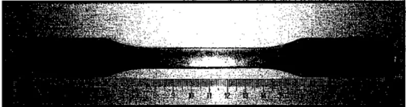
In order to extract the fibers from its matrix, the EFB-HDPE composites were boiled in xylene solution (2.0 mol/L). The granules of the composites after the extrusion process were immersed in the xylene solution and put in a furnace at 170°C for 6 hours. Figure 3-7 shows the fibers that have been extracted from the matrix after boiling process.
After extrusion
Extract EFB-HDPE
composites using xylene solution
Figure 3-7 Extraction process of EFB-HDPE composites after extrusion.
Then, separation process was conducted in order to separate the fibers from the chemical solution. These fibers were rinsed with distilled water and then placed in the drier at 80°C for an hour. Upon removal from the drier, these fibers were kept at room temperature for 1-2 hours. Finally, 100 of the fibers were taken randomly and their lengths were measured using a ruler.
After that, the samples that go through the injection molding process were taken and cut into 10 mm average length. These samples were placed in a beaker and put in a furnace at 190°C for 8 hours. For the injection molding's samples, the fibers were only extracted at about 80% and Figure 3-8 shows the fibers that have been extracted from the matrix after boiling process.
21
After injection molding
Extract EFB-HDPE
composites using xylene solution
Figure 3-8 Extraction process of EFB-HDPE composites afterinjection molding.
The last stage of the experiment is to investigate the fiber damaged on mechanical properties. The mechanical testing that took place was tensile and flexural
strength. At this stage, the sample were cut into average length 10 mm, and then immersed in the xylene solution at 190°C for 8 hours. The steps were slightly same as the process of extracting EFB-HDPE composites after injection molding.
Afterthat, these fibers were rinsed with distilled water and then placedin the drier at 80°C for an hour. Upon removal from the drier, these fibers were kept at room temperature for 1-2 hours. Finally, 100 of the fibers were taken randomly and
their lengthswere measured using a ruler.22
CHAPTER 4
RESULTS AND DISCUSSION
This chapter discusses the mechanical properties of the samples under the
influence of various temperatures during injection molding. The selected temperatures were 170°C, 175°C, 180°C, 185°C and 190°C. The temperature range was considered within the limits of the filler degradation temperature.4.1 Effects of Processing Temperature on Mechanical Properties
The fibers with average fiber length of 3-5 mm were used as reinforcing material in the study. Figure 4-1 shows the effect of temperature on tensile strength of the EFB-HDPE composites. It is observed that, there is a decrease in the tensile strength values as the temperature increases. At temperature 170°C, the tensile strength was 214 MPa, however it decreased by about 4% to 207 MPa when the temperature increased to 175°C.The decrease in tensile strength was up to 15% as the temperature increased from 170°C to 190°C. The results indicate that processing the composites at higher temperature may result in lower tensile strength properties. This could be translated into a weaker molecular structure (morphology) of the composite whereby the polymer chain may be less entangled or the interfacial bonding between the matrix and filler has weakened due to the effect of higher temperature. In addition, processing the composites at higher temperature may have caused more void formation which lead to poor mechanical properties.
23
250
t\3
175 180 185
Temperature (decyee Q
195
Figure 4-1 Tensile strength of EFB-HDPE composites at varying processing temperature.
The tensile modulus of the composites was increased up to 40% when the temperature increased from 170°C to 185°C as shown in Figure 4-2. The increase in tensile modulus indicates the ability of EFB to impart greater stiffness to the HDPE composites through increased amount of crystallinity of the polymer chains. The decrease in tensile modulus of the fiber composites as the temperature increases tol90°C maybe due to the maximum reinforcing ability that has already been reached by the fiber.
Figure 4-2 Tensile modulus of EFB-HDPE composites at varying processing
temperature.
24
The flexural strength of EFB-HDPE composites at varying temperature are presented in Figure 4-3. Initially, the flexural strength of the composites showed an increase of 7% as the processing temperature was increased from 170 to 175°C.
The flexural strength then continued to decrease by about 25% as the temperature
increased to 190°C.
30
25
£ 20
£ 15
? 10
IT 5
0
•; ^/*.***M *-*nl**Ej**% •-"
165 170 175 180 185
Temperature (degree C)
190 195
Figure 4-3 Flexural strength of EFB-HDPE composites at varying processing
temperature.
Unlike the tensile strength which is always decreasing as the temperature increased, the flexural strength increasedinitially and started to decrease when the temperature increased to 180°C and beyond. Basically, flexural loading causes tensile, compression and shear forces to develop inside the material. The increase
in flexural strength of the composites may be due to the ability of the composite
to transfer load into various forces inside the material, such as tension, compression and shearing, with different distribution at each layer, which makes the material's ability to withstand load improves at processing temperature of175°C.
However, composites processed at 180°C and above showed a reduction in its flexural strength due to similar phenomenon discussed earlier. The molecular chains of the polymer and the interfacial bonding between the matrix and the filler
25
may have been weakened during processing at high temperature resulting in poor
flexural properties. The formation of voids could also worsen the situation.
Apart from the effect of the processing temperature, the important factor that needs to be considered is the fiber attrition during processing that may reduce the fiber length and thereby affect the mechanical properties. As reported by Herrera [18], short fiber in polymer composites experienced shorting during extrusion.
This is further investigated in the following section.
While for the flexural modulus, it was increased up to 40% and starts to decrease at about 7% when the temperature increases to 185°C as demonstrated in Figure
4-4. Similar to flexural strength, the increase in flexural modulus of the EFB-
HDPE composites may be due to their capability to support the load that can be
transferred into various forces inside the material.
Figure 4-4 Flexural modulus ofEFB-HDPE composites at varying processing
temperature.
Modulus of rupture indicates the point of the composites that start to break. As illustrated in Figure 4-5, it shows that the modulus of rupture continues to increase as the temperature increases from 170 to 190°C. At high temperature, the polymer chains tend to crystallize more. The higher the amount ofcrystallinity in
26
the composite, the higher the stress needed for rupture. Unlike high temperatures, polymeric materials will become harder and more brittle due to exposure to low temperatures due to less molecular chain mobility.
26 25.5
• 25
J-24.5
IS 24 3
3 2a5
* 23
225
srfrafttf-f:-
165 170 175 180 185
Temperature (degreeC)
190 195
Figure 4-5 Modulus of rupture of EFB-HDPE composites
4.2 Fiber Damage Characterization during Processing
4.2.1 Fiber Damage during Extrusion
Duringprocessing, especially in extrusionprocess, fibers are damagedresulting in shorter fiber lengths. The amount of fiber attrition depends on the fiber content,
viscosity of the polymer melt and the melt-flow velocity. Figure 4-6 shows the
distribution of the initial fiber length (per-hundred) before extrusion and after extrusion process.The results indicate that the initial lengths of the fibers which are 3.0-5.0 mm in average were shortened after extrusion process. Based on the histograms, 56% of
the fiber decreased in their length. At the beginning of the experiment, all the
fibers are in the range of 3.0-5.0 mm in length, but at the end, 56% of the fibers are less than 3.0 mm in length.27
<i.oo 1.01-2.00 2.01-aoo aoi-4.oo 4.01-5.00 Fiber Length (mm)
• Before Extrusion
n After Extrusion
Figure 4-6 Distribution of fiber length before extrusion and after extrusion.
This phenomenon happened because during the processing, these fibers went through the twin rotating screws inside the heated barrel of the extruder which slowly shorten the length of the fibers due to the rotating screw speed which could be up to 120 rpm. In other words, the stress experienced by the fiber during the compounding process exceeded the fiber's strength and hence the fiber breaks or shortens in length.
4.2.2 Fiber Damage during Injection Molding
After the extrusion process, the granules were transferred to the injection molding
machine. Even though the temperatures were varied here, but there were nolonger changes in fiber length as the temperature increased. Figure4-7 and Figure 4-8 show the distribution of the fiber length (per-hundred) after injection molding
process at temperature 170°C and 190°C respectively.Based on histograms, about 59% of the fibers were shortened during injection molding compared to 56% during extrusion. This suggests that only a further 3%
of the fibers experienced damage due to the injection molding process.
28
30
25
20
15
10
5
0
< loo 1.01-2.00 zoi-aoo aoi-400 4.01-500
fiber Length (mm)
Figure 4-7 Distribution of fiber length afterinjection molding at temperature
170°C.
This is because, injection molding machine is not like an extruder which has twin rotating screw and breaker plate that caused the fibers to shorten, but it is a manufacturing machine that only functioning to produce parts from both thermoplastic and thermosetting plasticmaterials.
<1.00 1.01-200 201-a00 3.01-4.00 4.01-500 Fiber Length (mm)
Figure 4-8 Distribution of fiber length after injection molding attemperature
190°C.
29
While for the temperature 190°C, about 63% of the fibers were shortened during injection molding compared to 59% at temperature 170°C. It shows an additional 4% of the fibers experienced damage when the temperature increased to 190°C.
Table 4-1 tabulates the percentage of fibers damaged as the temperature was
varied from 170°C to 190°C.
Table 4-1 Percentage of Fibers Damaged at Varying Temperatures.
Injection Molding Processing Temperatures (°C)
170°C 175°C 180°C 185°C 190°C
Percentage of fibers
Damaged (%) 59% 59% 60% 62% 63%
From the table, it shows that there were no further shortening of the fibers when the temperature of injection molding process increased from 170°C to 175°C and only additional 1% of the fibers experienced further damage when the temperature was increased to 180 °C.
When the temperatures were increased to 185°C and 190°C, the percentage of fibers damaged also increased to 62% and 63% respectively. It can be observed that there has been a steady increase of fiber damage as the processing temperature increases from 170°C to 190°C although the increase may be considered minimal. The temperature increase may have caused the fibers to split or break more easily.
4.3 Morphological Studies on Fractured Surface of the Composites
According to the morphological studies of the tensile-fractured surface using
SEM, the failure modes of the high temperature composites during injection
molding are dominated by fiber pull out as illustrated in Figure 4-9. However, for the low temperature composites, plastic deformation in the form of matrix tearing is observed, as demonstrated in Figure 4-10.30
It can be inferred that, even though the high temperature composites experienced
fiber pull out, the contribution of the fiber in improving the mechamcal properties
is still observed. The incidence of fiber pull out indicates that there is load beingtransferred to the fiber to a limited extent.
lOOfim Mag = 100 X EHT =15.00kV Dale :ZApr 2009 Time :10:44:I8 wd= 20mm SgnaiA=SEi UniversitiTeknologi PETRONAS
^ • • I H B H i i ^ ^ H H H a n H r M
Fiber pulls
Figure 4-9 SEM micrographof the tensile-fractured surfaceof high temperature of the EFB-HDPE composites during injectionmolding and 100X magnification.
100pm Mag= 100X EHT = 15.00kv Date2 Apr2009 Time:10:52:06 ' ' wd= 11mm sig™iA=SEt Universiti Teknologi PETRONAS
Matrix tearing
Figure 4-10 SEM micrograph of the tensile-fractured surface of low temperature of the EFB-HDPE composites during injection molding and 100X magnification.
31
While for the low temperature composites during injection molding, matrix tearing indicates that the composites still possess ductile properties and the energy absorbed during mechamcal testing is mainly transferred in matrix tearing
formation.
32
CHAPTERS
CONCLUSIONS AND RECOMMENDATION
5.1 Conclusions
Processing techniques such as injection molding and extrusion can cause high fiber attrition and reduction in the fiber length. The current study showed that major fiber damage happened during the extrusion process where 56% fibers were shortened. This phenomenon is largely due to the effect of the rotating screw of the machine during the compounding process. During the injection molding process, only further 3% fibers were damaged with fiber length less than 3mm.
As the injection molding temperature was increased from 170°C to 190°C, the amount of fiber damaged increased steadily from 59% to a maximum 63%. The increased in temperature has weakened the fibers and caused them to break more
readily. The study also found that the tensile and flexural strength decreased as the processing temperature increased. The opposite trend was observed for the tensile and flexural modulus exceptat 185°C and 190°C. The findings showed that using high processing temperature may affect the mechanical properties of the
composites.5.2 Recommendation
In this case, the fiber shorting phenomenon during processing could be investigated further. It could be carried out by boiling the composites in xylene and the fiber then extracted. Image analysis to measure the fiber length using two point measuring mode may serve as the best method as it can generate more
accurate and statistically representative data.33
REFERENCES
[1] Kumar, R.N., Rozman, H.D., Abusamah, A., and Chin, T.H., 1994,Sheet Moulding Compounds Based on Palm Fruit Pressed Fiber, National Seminar on Utilization of Palm Tree and other Palms, Forest Research Institute of Malaysia (FRIM),.
[2] Khalil, H.P.S. and Rozman, H.D., 2000, Polym.-Plast Technol Eng, 39, p.
757,.
[3] Ismail, H., Jaffri, R.M., Aminullah and Mohd Ishak, Z.A., 1998, Int. J. Polym.
Plast Technol. Eng, 37,493.
[4] Raj, R.G. and Kokta, B.V., and Daneault, C. 1989, International J. Polymer
Material, 12, p. 239.[5] M. Wladyka-Przybylak, 2004, Uses ofNatural Fiber Reinforced Plastics, in
Natural Fibers, Plastics and Composites, F.T. Wallenberger and N.Weston, Editors. Kluwer Academic Publishers, p. 263-274.
[6] Sreekala, M.S., M.G. Kumaran and S. Thomas, 1997, Oil Palm Fibers:
Morphology, Chemical Composition, Surface Modification, and
Mechanical Properties. Journal of Applied Polymer Science,. 66:p. 821-
835.
[7] Hartley, C.W.S., 1997, The Oil Palm, 3rd ed., Journal of Reinforced Plastics and Composites 2005.24(2): p. 122-134 Longmans, London,.
[8] Kawawada, Karen, The Record. 22 May 2008
<http:/en.wilriDedia.org/wiki/HDPE>
34
[9] Maldas, D., Kokta, B.V., Raj, 1998, Polymer, Journal of Applied Polymer Science, 1996.29,1255,.
[10] Valadez-Gonzalez, A., et al., 1999, Effect ofFiber Surface Treatment on the Fiber Matrix Bond Strength of NATURAL Fiber Reinforced Composites. Composite: Part B,. 30: p.309-320.
[11] Kavelin, K.G., Investigation ofNatural Fiber Composites Heterogeinity with respect to Automotive Structures. 2005, Delft University of Technology.
[12] Bismarck, A., S. Mishra, and T. Lampke, Plant Fibers as Reinforcementfor Green Composites, in Natural Fibers, Biopolymers, and Biocomposites, A.K. Mohanty, M. Misra, and L.T. Drzal, Editors.
2005, CRC Press, p. 37.
[13] Rong, M.Z. et al., Composites Set Technol, 61,1437-1447,2001.
[14] J. KAHOVEC, R.B. FOX and K.HATADA; ''Nomenclature of Regular Single-Strand Organic Polymers. 05-12-2006.
<http:/en.wikipedia.ora/wiki/Polvethvlene>
[15] Clark J. E.; Luthy, R. V. (1955). "Separation of Xylenes". Ind. Eng Chem.
47 (2): 250-253. 07-10-2003.
<http://en.wikipedia.org/wiki/Xylene>
[16] Li, Y., Y.-W. Mai, and L. Ye, Sisal Fiber and Its Composites: A Review of RecentDevelopments. Composites Science and Technology, 2000.
60:p.2037-2055.
[17] Xanthos, C.H. Chunda N., Mandell JF, Folkes M.J, 1983, Plast. Processing Tech. Appl. 3, p. 223.
35
[18] Herrera-Franco, P. and A. Valadev-Gonzalez, 2005, A study of the Mechanical Properties of Short Natural-fiber Reinforced Composites. Composites: Part B,. 36:p. 597-608.
[19] Folkes MJ, .V., D.V. Rosato, and M.G. Rosato, 2000Jnjection Molding Handbook. 3rd ed.: Kluwer Academic Publisher.
[20] Mandell, Kavelin, K.G., Investigation of Natural Fiber Composites Heterogeneity with respect to Automotive Structures. 2005, Delft University of Technology.
[21] H. Ismail, Salmah, and A.A. Bakar, Effects of Chemical Modification of Paper Sludge Filled Polypropylene (PP)fEthylene Propylene Diene Terpolymer (EPDM) Composites. Journal of Reinforced Plastics and Composites, 2005.00(00).
[22] Mohanty, Kalaprasad, G., et al., Theoretical Modelling of Mechanical
Propeties of Short Sisal Fiber Reinforced - Polypropylene Composites. Journal of Materials Science, 1997. 32: p. 4261-4267[23] Mallick, P.K., 2000. .Particulate and Short Fiber Reinforced Polymer
Composites. Comprehensive Composite Materials, 2: p. 291-331.[24] Annual Book of ASTM Standards, Vol 01.03, A 370 - 97a, Standard Test Methods and Definitions for Mechanical Testing of Steel Products.
36
APPENDIXT No.Detail/Week12345679 M I D S E M B R E A K
1011121314 1ProjectWorkContinue •Continuelabworkatblock17-Determinethe tensilestrengthfortheEFB-HDPEbyusingUTM 5kN. •5specimensweretestedandatleast3replicate specimenswerepresented. *Graphobtainedanddatawillberecorded • 2SubmissionofProgressReport1 3ProjectWorkContinue •Continuelabworkatblock-5(Chemicalblock). Investigatefiberdamagecharacterizationofthe composites. •Immersedthecompositesinxyleneat175°Cfor6 hours. •Afterthematrixandfillerwasextracted,separate thefiberandrinsewithdistilledwater. •Putthefibersinthedrierat80°C. •Measurethelengthofthefibers. * 4SubmissionofProgressReport2 • 5Seminar(compulsory) •Examiner:Dr.BambangandDr.SibiChacko. •Makesomecorrectionsindatacollected. 6Projectworkcontinue •Redotheexperimentsespeciallyinmechanical testings(TensileandFlexuralTest) m 7PosterExhibition
8SubmissionofDissertation(softbound) •Makesomechangesinresultsanddiscussions• 9OralPresentation •Examiners:Dr.BambangandDr.SibiChacko• 10SubmissionofProjectDissertation(HardBound)•
![Figure 2-1 Classification of natural fibers derived from plants [12],](https://thumb-ap.123doks.com/thumbv2/azpdforg/10247315.0/17.846.134.767.228.659/figure-classification-natural-fibers-derived-plants.webp)
![Figure 2-2 Structure of natural fibers [13].](https://thumb-ap.123doks.com/thumbv2/azpdforg/10247315.0/18.846.211.631.96.426/figure-structure-of-natural-fibers.webp)
![Figure 2-3 The repeat unit of polyethylene [14].](https://thumb-ap.123doks.com/thumbv2/azpdforg/10247315.0/18.846.323.476.890.1017/figure-the-repeat-unit-of-polyethylene.webp)
![Table 2-1 Physical and mechanical properties of selected natural fibers [12].](https://thumb-ap.123doks.com/thumbv2/azpdforg/10247315.0/19.846.105.752.230.565/table-physical-mechanical-properties-selected-natural-fibers.webp)
![Figure 2-4 Three aromatic hydrocarbon isomers of xylene [15].](https://thumb-ap.123doks.com/thumbv2/azpdforg/10247315.0/20.846.181.672.248.485/figure-aromatic-hydrocarbon-isomers-xylene.webp)
![Figure 2-5 Photograph of an extruder machine [17].](https://thumb-ap.123doks.com/thumbv2/azpdforg/10247315.0/22.846.171.624.408.714/figure-photograph-of-an-extruder-machine.webp)
![Figure 2-6 Photograph of an injection molding machine [17].](https://thumb-ap.123doks.com/thumbv2/azpdforg/10247315.0/23.846.132.669.93.469/figure-photograph-injection-molding-machine.webp)