The theory of shock dynamics in two dimensions is reformulated to treat shock propagation in a non-uniform medium. The analysis yields a system of hyperbolic equations with source terms that represent the generation of disturbances on the shock wave as it propagates in the fluid inhomogeneities. The theory is applied to problems involving the breaking of a planar shock wave at a free planar gaseous interface.
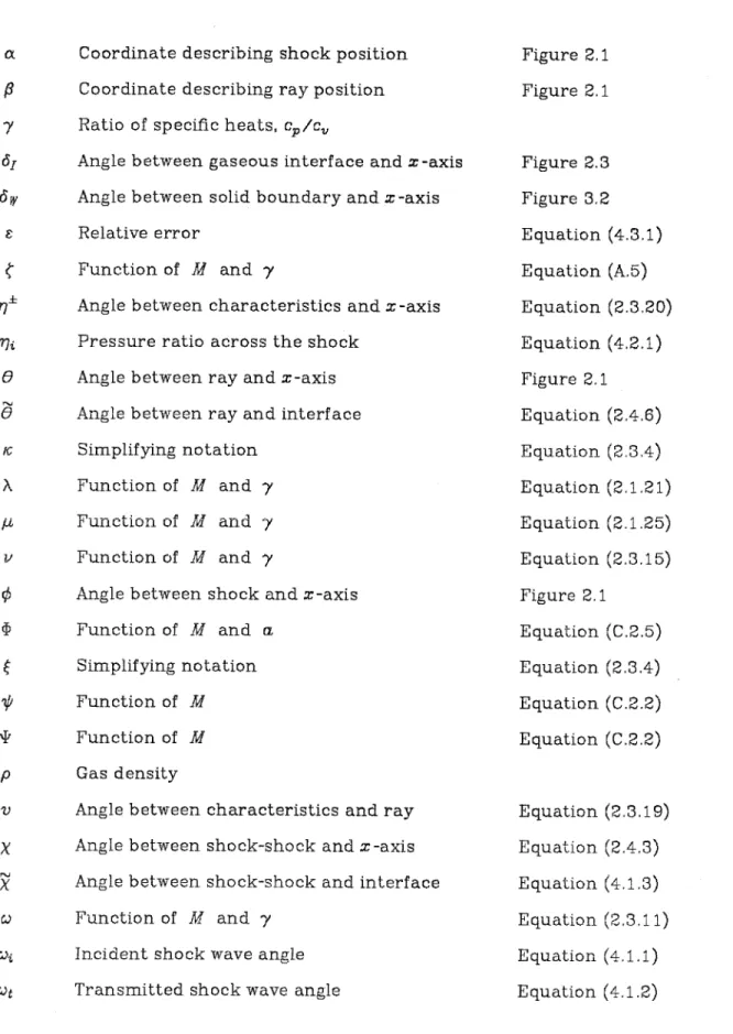
Integration of the ray tube area function 66 B. Shock wave interaction with a normal contact BO discontinuity. Transmitted shock wave angle (,)t versus incident shock wave angle (;)i for breaking a plane shock at a contaminated carbon dioxide–helium interface. Function of M and ?' Simplifying notation Function of M and / Sirn.plifying notation Function of M and ?' Riemann invariants.
Angle between features and radius Angle between stroke-stroke and x-axis Angle between stroke-stroke and interface Function of M and 7 .
Chapter 1
In general, regular refraction occurs when the angle between the shock front and the interface is small, while irregular refraction occurs when the angle of incidence is large. The theory involves the treatment of wave-like disturbances, which propagate at the shock front and carry information about the changes of shock strength and beam angle. They attempted to solve the problem of a shock propagating in two half-planes separated by a free surface by imposing the condition that the two parts of the shock front at the free surface move at the same velocity.
The present work reformulates the theory of shock dynamics in a non-uniform environment, using Whitham's characteristic rule, and derives a fully general expression for the area-Mach number relationship that accounts for any spatial variation in the environment ahead of the shock front. As mentioned above, a case of particular interest is that in which discontinuities in fluid properties, that is, contact discontinuities, occur ahead of the shock front. In Chapter 2, the shock dynamics equations are reformulated to include the effects of sound speed changes in the environment ahead of the shock front, which may be caused by spatial changes in the thermodynamic state or gas concentration, or by the presence of forces of the body.
It is these source terms that generate perturbations on the shock front as the shock propagates through the inhomogeneities.
Chapter 2
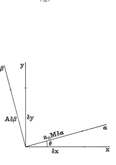
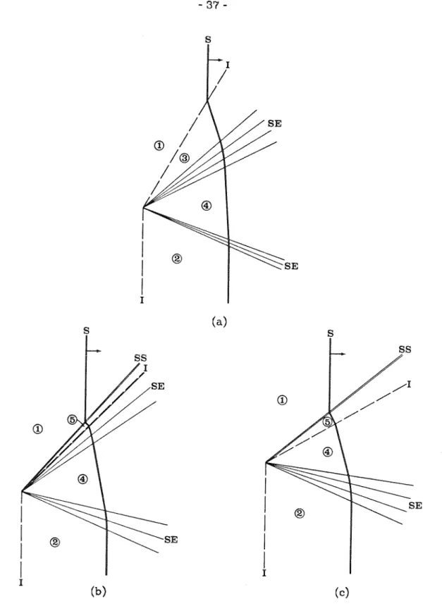
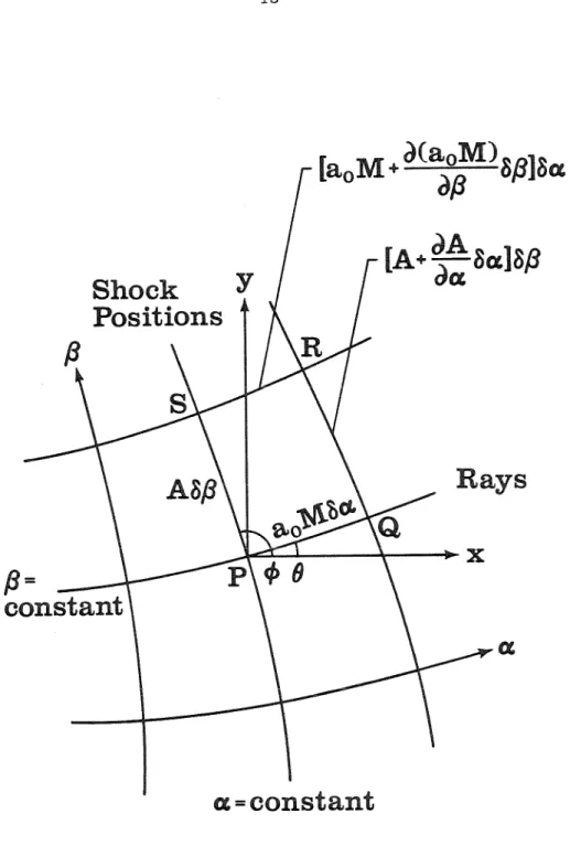
We note that equation (2.1.20) treats any spatial variations in the perfect gas ahead of the shock front. Physically, the shock-shock is the locus of the triple-shock intersection, and its appearance indicates the formation of a Mach strain. To remove the x -dependence of the source terms, we introduce a simple rotation of the shock and the interface through an angle -OJ, so that the interface lies parallel to the x axis.
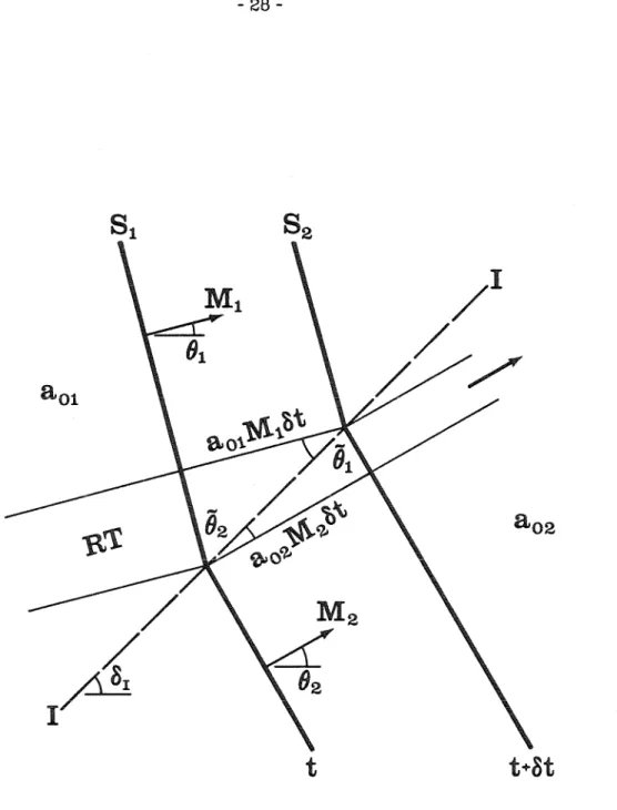
To complete the solution of the jump conditions across the interface, the slope of the shock front in the secondary region is found from equation (2.4.8). When e = o1, the shock is normal to the interface and the jet tubes do not cross the interface. S1 is the shock front and S2 is the shock front at a subsequent time after interaction with the interface.
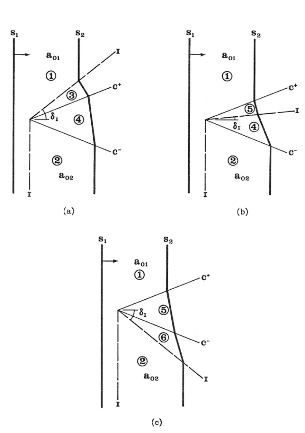
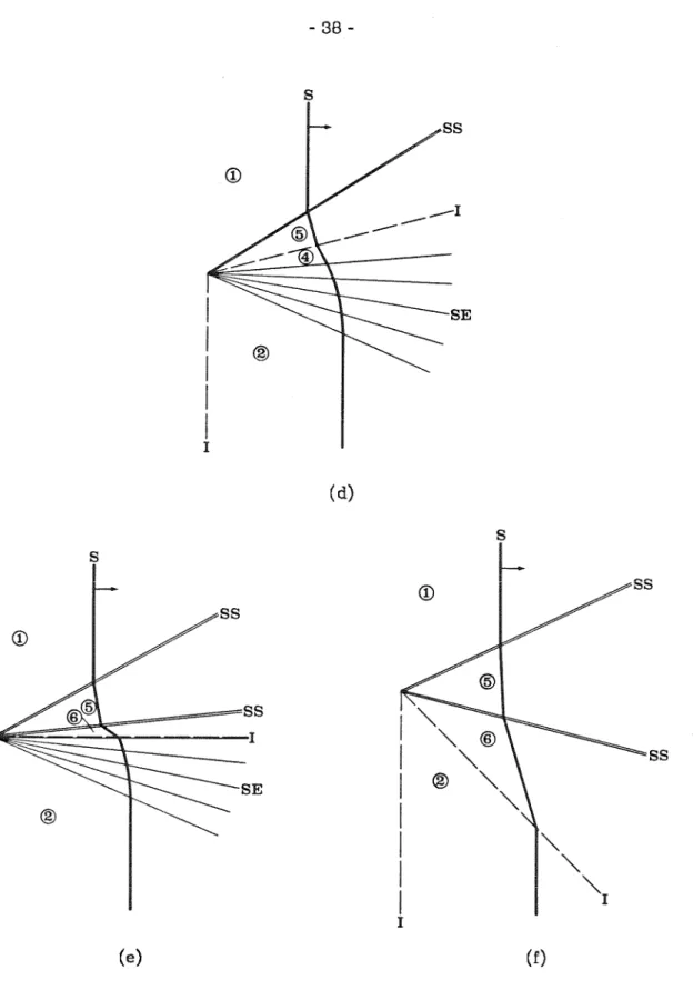
The shock is transmitted through the vertical part of the contact surface and breaks from the other. As the interfacial angle is further reduced, the shock-shock separates from the interface, as shown in Figure 3.3(b) (Case 5), and the upper shock expansion decreases, until it finally disappears (Case 6). As the interface angle continues to decrease, the shock front becomes perpendicular to the interface (case 8) and then reverses the curvature (case 9) from convex forward at the interface to concave forward, as shown in Figure 3.3(d). .
For case 8, in which we designate the interface angle as 61, we note that the shock fronts on both sides of the interface are perpendicular to the interface, so the jet tubes do not cross the interface. For even smaller interface angles, the shock-shock may be sufficiently weak that the effects of the interface are again compressive (cases 9 and 10), and the cycle repeats itself through the formation of a second shock-shock (cases 11 to 15). As the interface angle is reduced, the shock shock weakens, degenerates into a c+ characteristic (case 17), and is converted into a shock expansion as shown in figure 3.4(b) (case 18).
The transition from shock-shock to shock-expansion causes regions 2 and 3 to become identical (case 17), and corresponds to a zero contribution of the angular signal, referred to by Jahn (1956). However, as the interfacial angle decreases, the shock travels to the interface (case 25), crosses it (case 26), and moves outward into the primary medium, resulting in a simple, irregular refractive result (case 27). . As the force of the incident shock decreases, the force of the shock becomes against the wall, ma'am.
However, in the case of problem 2, the part of the shock front below the interface comes only from the ray tubes crossing the interface from above.
Chapter 4
The experimental result has a discontinuous main shock front and a precursor wave at the interface. Shock dynamics, on the other hand, tries to find a solution where the main shock front is continuous across the interface. Thus, although the result for case 46 is approximate, the agreement of the theory with the experimental result shows that under these conditions the shock front is not continuous at the interface.
This series of incident wave angles corresponds to the bound precursor series discussed by Abd-el-Fattah, Henderson and Lozzi. Their photographs show that in this range the transmitted wave is slightly ahead of the incident wave at the interface. Although their results were not conclusive, they did note that both the incident and transmitted shock fronts had the same, or very nearly the same, velocity along the interface, and they inferred that the discontinuity of the shock front at the interface was the result of one or other non-pseudo-stationary process on the corner.
This series of incident wave angles corresponds to the free precursor result discussed by Abd-el-Fattah, Henderson and Lozzi, in which the velocity of the precursor (transmitted wave), Their measurements indicated contamination at the interface, and that the methane was only 90% pure (10% by volume of carbon dioxide), giving a sound speed ratio across the interface of about 1.54. For the strong group, shock dynamics predicts anomalous refraction from transition at through 61 = 0°, i.e. until the interface lies on the wall.
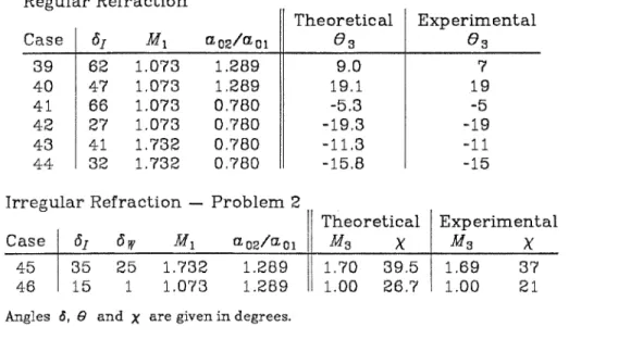
Abd-el-Fattah, Henderson and Lozzi (1976) calculated the transition angles for refraction of a plane shock at a pure carbon dioxide - helium interface as a function of the incident shock strength. The results of the current theory are entered as data points in the figure. Again, for simplicity, we have taken the ratio across the interface as unity, instead of using the actual value of 1.28.
An interesting check of the accuracy of the theory can be done in the case of Problem 1 with o1 = 90°, for which the shock interacts normally with the interface (table 4.2). Their solution essentially has two regions lying adjacent to the interface, and they find that the beam angle changes from about 19° above the interface to about 3° below.
Chapter 5
1957 The motion of a shock wave in a channel, with applications to cylindrical and spherical shock waves. Equation (A.B) is a more compact form of the expression obtained independently by Henderson (1980), who also pointed out the errors in the expression published by Bryson and Gross (1961). To study the behavior of (C.1.1) at the singularity, it is first shown that M is bounded, and then the right-hand side of the equation is expanded in a Taylor series around the singularity (r0 , M0.
When a shock wave is incident normally at an interface separating two regions of gas at different sound speeds, in general, the result is a transmitted wave and a reflected wave. The transmitted wave is always a shock, while the reflected wave can be either a shock or an expansion, depending on the properties of the gas on either side of the interface. The powers of the transmitted and reflected waves can be found by matching the gas pressures and velocities across the interface.
Interaction of a shock wave with a normal contact discontinuity when the reflected wave is an expansion. Equation (D.1.13) gives the strength of the transmitted shock at a normal interface in terms of the strength of the incident shock and the ratio of the speed of sound when the reflected wave is a shock. In the reflected expansion wave, the Riemann invariant on the characteristic c+ is preserved, so that.
Equation (D.2.13) gives the strength of the transmitted shock at a normal interface in terms of the incident shock strength and the sound speed ratio when the reflected wave is an expansion. Equation (D. l. 13) is an expression for the strength of the transmitted shock when the reflected wave is a shock, while equation (D.2.13) is a similar expression for the case where the reflected wave is an expansion. At the transition from a reflected shock to a reflected expansion, the reflected wave is an acoustic wave, so that from equation (D.1.11) or (D.2.11), Mt= Mi.
In summary, with a decrease in the speed of sound across the interface, the transmitted shock is stronger than the incident shock and the reflected wave is a shock. This appendix contains information about the algorithms used in the shock absorption calculations and provides an overview of the most important sub-programs. C THIS FUNCTION SUBPROGRAM EVALUATES THE SLOPE OF THE C SHOCK SHOCK LINE IN RELATION TO THE X AXIS.
C THIS FUNCTION SUBROUTINE CALCULATES THE SLOPE OF THE C CHARACTERISTIC LINE RELATED TO THE FLOW DEFLECTION ANGLE.