In fact, the melancholy situation in the 1950s was that the introduction of radar did not lead to any reduction in the number of serious collisions at sea. The Royal Institute of Navigation has generously provided a rare copy of The Uses of Radar at Sea.
Introduction
Purpose and scope
The operator always decides whether and how to use the radar and its information. The connected components of the radar - transmitter, scanner, display - are often called a system.
Radar users and uses
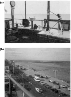
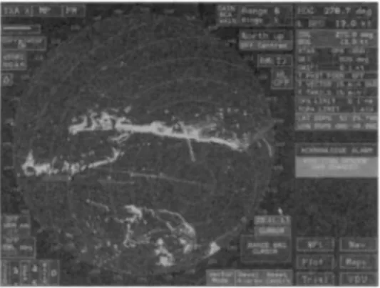
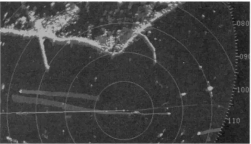
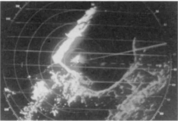
The watchman is usually the skipper or mate who operates the radar for most of the above tasks. At the other end of the scale, coastal surveillance radars are used by coastguards and voluntary organizations to keep watch on coastal vessels near popular resorts, especially where currents can so often cause problems for the inexperienced, see Figure \A(a) -(c).

The past and future
At the other end of the scale, miniaturization and price reductions allowed smaller vessels to benefit from radar, and a large specialist yacht market developed, particularly in the United States and the Far East. Sollosi [10] gives a useful summary of the VTS function and the problem of combining radar and AIS data.
The regulators
- UNCLOS
- IALA
This paragraph is reproduced from Seaways, The International Journal of The Nautical Institute, April 2002, 'Nautelex', Brian Bailey. As with any other radio device, radar transmissions are regulated by the Radiocommunication Sector (ITU-R) of the International Telecommunication Union.
The regulations
This standard is, in fact, an extension of the above and describes additional requirements for radars to be installed in HSC. We have tried our best to keep the inevitable mathematics of calculations as simple as possible.
The layout of this book
Some of the values reported in the literature are reviewed, followed by an attempt to clothe the experimental results with an elementary theoretical justification. At the end of this chapter, all the information needed to calculate the average echo strength of all target classes is collected, including variation with range, weather, and other environmental factors.
7 LANG, G.: 'IfGPS fail', Seaways, The InternationalJournal of the Nautical Institute, 2002, report of a meeting of the Royal Institute of Navigation Technical Committee, 26 June 2002. 9 COX, P: 'Memories of surface warning radar' Transmission lines , The Newsletter of the Defense Electronics History Society, Bournemouth, UK SOLLOSI, M.: 'The Automatic Identification System and Ship Traffic Services',.
The system and the transmitter
The operator and the system
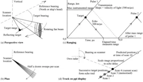
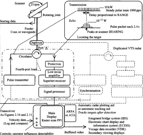
The Master or 0OW then monitors the proceedings, partly by observing the radar secondary viewing screen, but remains in control. The traffic area of port VTS usually extends well to seaward of the port area. Object bearing is that of the antenna, range is measured by the delay before reception.
Components of the radar
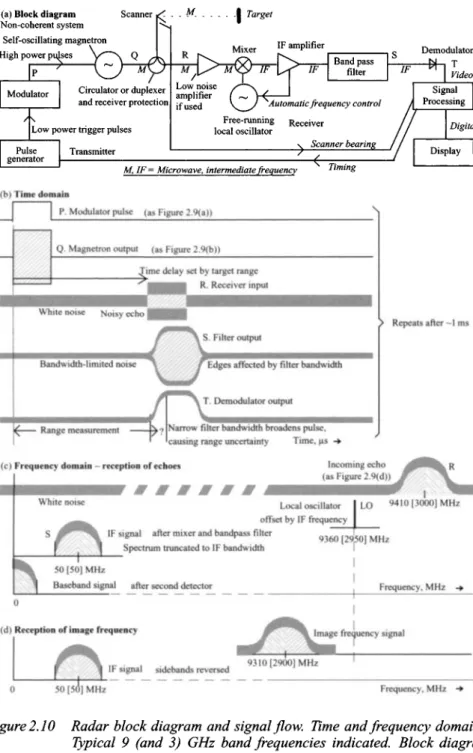
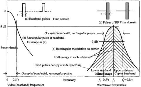
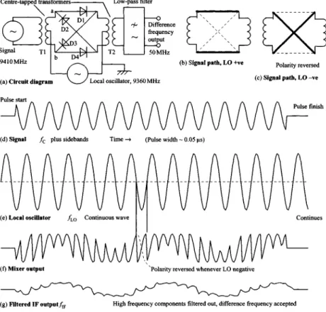
The amplitude of the nth harmonic, Vn (with frequency fn = nk/x Hz) is found by. This envelope detection process preserves the envelope of the IF and microwave signals (compare Figure 2.10 S and T). A coupler (a pair of parallel waveguides connected by small slots, or parallel stripline conductors) extracts a sample of the actual generated transmitter frequency, from which the pulse sidebands are then removed.
Transmitter
This moment is arranged to coincide with the transit time of the rotating beam to Pole 2, which feeds more energy into the tuned circuits. Intermediate C-shaped cavities form the tuned circuits of the cavity resonators within the copper anode block. When the supply is long, quite small frequency change sharply changes the phase of the mismatch power sent back to the magnetron.
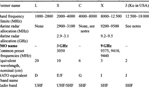
Transmitted frequency
As we have seen, the transmission frequency of incoherent radars is not under the control of the user - the tuning control does not work on the transmitter, but on the receiver. Marine radar must use a centimeter frequency, with lower frequencies giving poor illumination of the sea surface and higher frequencies suffering from excessive precipitation. Choosing the best belt for a particular application depends on several factors and should be made after a detailed cost/effectiveness/benefit analysis using the methods in Chapter 15.
Choice of other parameters
Long-range precipitation attenuation: slight at 3 GHz, moderate to severe at 9 GHz, prohibitive at 14 GHz. Radar data sheet power can mean: (a) power at the magnetron output or (b) the power available at the transceiver enclosure flange or at the scanner flange when the scanner is integrated with the transmitter. For equal performance, it may be cheaper to choose a set with receiver noise 1 dB lower, or to shorten the path of the feeder to reduce its one-way loss by 0.5 dB (see below).
Feeder
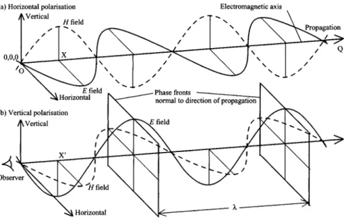
When a plane wave such as that of Figure 2.14(a) strikes a perfectly conducting metal plate placed perpendicular to the direction of propagation. the magnetic field component of the wave induces circulating surface currents of finite amplitude in the plate; without resistivity there can be no tension in the plane of the plate. Immediately above the surface there must be a canceling electric field that is in phase opposite to the incident wave. The speed of information propagation in the guide is called the group velocity and is the forward component of the velocity vector.
Scanner, qualitative description
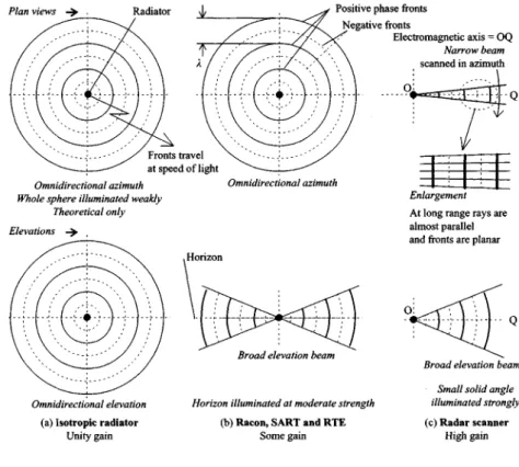
An isotropic radiator, Figure 2.17(a), is an antenna that radiates uniformly through the entire 360° x 360° (4n sr) of the surrounding space. As also shown in Figure 2.25(a), a small primary radiator (sometimes confusingly called the power supply) is mounted in front of the reflector. The primary radiator is usually located under the dish (Figure 2.25(b)) to keep it out of the beam.
Quantitative scanner analysis
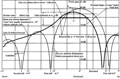
In the cosec2 elevation region, for a half-power beamwidth of 0 rad: .. voltage at v rad off-axis = ) numerical. The pattern locus lies a few decibels below the sidelobe peaks of a uniformly illuminated scanner of the same size, due to the energy transferred to the former null angles. When considering the operation of any type of scanner with an off-axis target of angle v, and with a beam width of half power O9, the gas loss factor is defined in the same way as ge\.
Radar receiver
Scanner - receiving
Receiver input
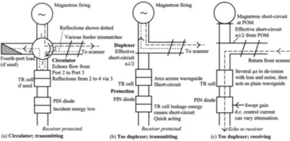
During de-ionization, the attenuation of the TR cell (incorporated in the swept gain attenuation) and the noise generated by the ionized gas affect the reception of short-range echoes. The TR cell and in particular the PIN switch also protect the receiver from powerful transmissions received by other radars as interference. A TR cell or PIN diode placed an integral number of half wavelengths apart causes the dual receiver gate to appear short-circuited, directing all transmitter power to the scanner.
Receiver and filter
The first amplifier stage dominates the noise performance of the entire system because its noise is the most amplified. Therefore, great attention is paid to reducing the sources of pre-amplification noise and the noise generated in the first stage of the receiver. Therefore, great attention is paid to reducing the noise factor of the first amplifier stage.
Superhet receiver and mixing
In non-coherent systems the LO frequency is subject to similar but smaller frequency shifts as some of those in the microwave. This is not important if there is only one pulse, but the integration gain of non-coherent systems relative to their coherent cousins is lower and increases more slowly with N9 the number of pulses in the packet. The integration loss (relative to perfect integration) approaches A/TV numerically or 5 log Af dB, and is thus greatest when there are many pulses in the packet, on short-range scales where prf is highest;
IF amplifier, demodulator and video sections
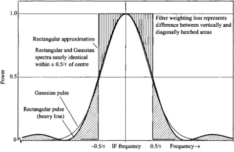
If the filter bandwidth is too wide, all frequency components of the signal are indeed accepted, but with a lot of noise, where the noise is proportional to the bandwidth. The amplitude/frequency transfer function is the complex conjugate of the Fourier transform (in frequency domain) of the signal pulse shape. When the radar is used conventionally, all parts of the echo are detected and displayed as an axial trace.
Signal processing basics
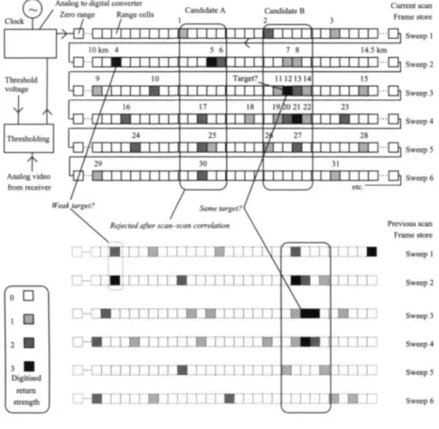
The threshold voltage is set partly by the processor, by reference to the clutter environment (generally assessed by the average cell content) and partly by the operator's use of the gain control. The detection threshold in any part of the monitoring area is automatically adjusted to match the average local root when referring to the map. Control of the time frame or persistence of the track may be provided as an operator control.
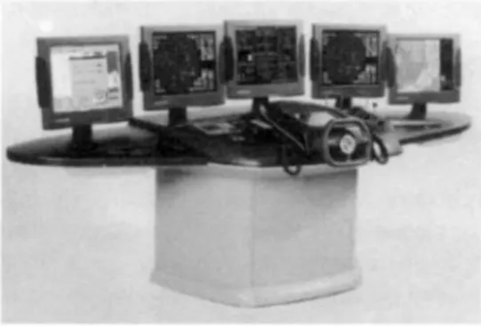
Display principles
On the other hand, the mainframe can be duplicated for reliability at moderate cost, and the tracking and clustering algorithms are easy to adapt to prevailing circumstances. Graphs are reported scan-by-scan centered at moderate bandwidth for later post-processing and trace shaping. 100 |xA to fly to the glass screen at the front of the tube, which is pulled by a grounded metal cylindrical anode (plate) inside the neck.
Raster scan display
The beams are electrostatically focused to sharp points and can be directed by the time base system to any part of the screen by applying voltage to pairs of deflector plates (or by current to pairs of coils) surrounding the neck. To support text and graphic data and to avoid degradation of echoes, radar displays need higher resolution than television. The digital input format facilitates the connection of secondary displays using local area network (LAN) techniques.
Cursive display
Each pulse causes the phosphor in the diffuser scale location to glow dimly, fading after 20 seconds or so. Luminance is a measure of the strength of the echo, within the limits set by the dynamic range of the phosphor, augmented by the previous soft limiting applied to the video. Indeed, the earliest large devices such as the BTH RMS-I came in their own separate cockpit, the operator calling out indicated plots by voice on the bridge in the tradition of crow's nest surveying.
Plots on the screen
Under ideal conditions, raw radar detection performance is little worse than that of modern equipment, and the same detection calculations can be used with an operator correction that takes into account: (a) inadequate control settings and (b) failure to detect displayed targets, perhaps faintly, on the display. They can be allowed for by assuming a high detection probability threshold or by adding an operator loss term, Lo p, to the radar range equation.
Radars for special purposes
The strict 35m range discrimination requirement specified in the HSC Code requires short pulse lengths and many beam cells. Although built especially hard to withstand combat impacts and has some special features, especially in the display area, it is essentially a civilian naval radar, with similar transmission characteristics. Warships on training in the Mediterranean are believed to have moved undetected by 'hostile' forces for several days.
Calibration
It was about a kilometer long and measured the entire system capacity, including the scanner and the source. Its echo appears in all directions like a sunbeam around one's own ship; radius is the measure of the system without scanner and feeder. For this, a small neon lamp is mounted on the static housing of the scanner drive.
A few were detected by the scanner and displayed as feathers or feathers on the box bearing. Nowadays, the echo box is usually loosely coupled to the scanner feeder and has an electromechanical preset to the magnetron frequency. Although these arrangements do not pretend to be accurate, they have two major advantages: they check the entire radar system, including the scanner, and they are system independent.
Echo strength in free space
- Introduction
- Radiated power density
- Passive reflector; radar cross section, radar range equation
- Active target
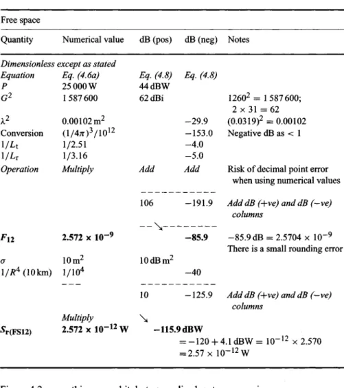
- Range equations in practical form
- Calculations and graphs
- Limitations of free space formulae
For example, RCS of a flat conductive plate falls off rapidly when it is turned obliquely to the radar. This form of the radar range equation relates the radar parameters (such as transmitter power, scanner gain, received signal strength) to target and external factors (such as RCS and range). We include radar receiver loss, to give the signal strength at the radar receiver of the response broadcast.
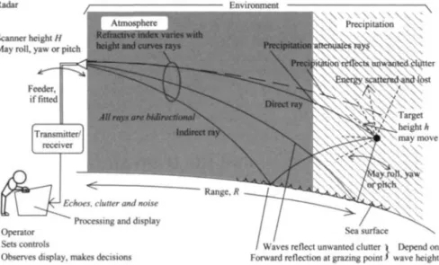
Environmental effects on propagation
- Scope of chapter
- Atmospheric refraction
- Measurement of refraction factor
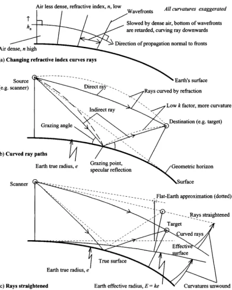
- Ray geometry; geometrical optics
For a given frequency, increasing n from 1 by inserting the atmosphere, A., reduces the distance traveled per cycle, thus reducing the propagation velocity below the free space value. This flat-earth approximation (indicated in figure 5.1(c)) is equivalent to setting E = oo, with k = oo as well. As shown in Figure 5.2(d), decay rate can be negative in the first tens of meters above the surface before becoming positive.