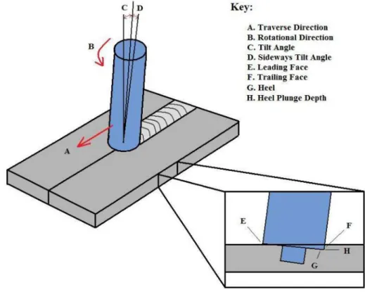
The rotating tool is dipped into the joint line until the shoulder contacts the top of the plates. The stirring and mixing of the material is the result of the rotation of the tool, and the stirred material from the front to the back of the pin is moved by the translation of the tool. Nevertheless, the parameter that most controls the heating is the frictional coupling of the tool surface with the workpiece.
In addition, another important process parameter is the angle of the spindle relative to the surface of the workpiece, or it is sometimes known as the tool inclination (see Figure 3). Sometimes it is desired that there is a slight inclination of the spindle towards the rear direction. This will lead to inefficient movement of the material from the face of the tool and may cause internal channel or surface groove welds.
Also in the extrusion zone, within a limited width, the material will flow around the pin from the front to the rear of the tool. The area where the material from the front of the tool is forced into the cavity left by the forward moving pin under conditions of hydrostatic pressure is called the forging zone. The index point is the location on the transducer where the main beam of ultrasonic sound exits the transducer and enters the material.
The beam angle is the angle the main beam travels in the material and is measured from the normal of the incoming surface. A transducer's beam spread is the angle between a particular edge in the cone to the other side of the same particular edge (eg 10% edge – 10% edge). Before starting the welding, the tool is first placed over the desired starting point for the welding.
Figure 14, The left side of the image shows the resulting "Exit Hole" effect when the tool is removed from the material. The transducer is then turned to face the 50mm radius surface and the procedure is repeated for the other side of the transducer. The SS stands for Shear Wave which is the propagation mode of the sound wave.
70o is the nominal angle sound travels in carbon steel and 4MHz is the center frequency of the transducer. The time-of-flight of the ultrasound was taken at intervals as the temperature rose and also as it was cooling down. For consistency, the TOF was taken as the positive maximum point of the received signal (Appendix B).
The advantage of having a tapered shoulder tool is the ability to control the width of the weld so that it does not interfere with the US transducers located behind the tool.
The tool has a and a threaded pin
Before each weld, coupling agent was placed on the sample along the path that the transducers would take and a reference TOF was taken for the initial temperature of the sample. During welding, coupling agent was continuously sprayed onto the sample to ensure that there would not be any loss of coupling, which in turn would lead to a loss of the US signal. It was also noted that with the increase in temperature, the shape of the US pulse would change and it was sometimes more difficult to find a positive maximum.
During the experimental part of this study, it was found that the motors of the FSW vehicle, mainly the vertical motor and the shaft motor when driving the FSW vehicle caused significant interference to the US instrument system. The interference was magnified when the gain was increased to compensate for the temperature rise according to the temperature calibration, leading to saturation of the oscilloscope and a total loss of the US signal. It was also noted that the volume was more forgiving when it came to interference, but both installations experienced a loss in the US signal even before the vehicle began traversing the weld (ie during the dive routine) causing the hardly get any meaningful data.
The interference is thought to be less due to the mechanical vibration of the FSW system and more to the electromagnetic interference of the motors. By changing the active element, it may be possible to operate the transducers at a lower gain setting and therefore a reduction in exposure to the interference. Type – The use of non-contact electromagnetic acoustic transducer (EMAT) probes that are less susceptible to the high temperatures that will affect the piezoelectric crystal.
Therefore, a smaller gain would have to be added to keep the amplitude of the received signal at a certain level. The challenge with them would be trying to overcome the limitations of the ultrasound beam. It is likely that a change to the layout proposed in this paper could allow inspection of the overlay welds.
Comparisons can then be made with previous models such as those of Nunes et al. 2001) and also to the torque measurements obtained with the FSW machine. The temperature calibration results showed that there is a strong correlation between the change in the time of flight of the ultrasonic waves and this change in the temperature of the sample. The use of ultrasonic TOF also has the advantage of measuring weld temperatures without the need to drill holes and embed foreign objects in the sample, which could affect the welding process and cause inaccuracies.
GB SS 70(St) 4MHz SN:72330
GB SS 70(St) 4MHz SN: 72331