In my opinion, the thesis has reached the standard that meets the requirements for the award of the degree of Doctor of Philosophy in accordance with the regulations of the institute. Also thanks to CIF HOC, staff and TA of SEM and FESEM for their helping hand in analyzing the samples.
Abstract
One of the problems that occurs in dissimilar welding is the formation of intermetallic compounds (IMC) in the weld zone, and the presence of IMC degrades the quality of the weld. Whereas in the case of Zn, thin, continuous and uniform IMCs are formed within the weld zone with improved mechanical and metallurgical properties.
List of Acronyms
Nomenclature
FESEM images of fractograph without interlayer (a) Al/Cu-EWF2 failed on Al side, (b) Al/Cu-EWF3 failed on NZ/TMAZ interface. XRD analysis of the welded samples on the Al side, the middle and the Cu side on the cross section of the Al/Cu joint (a) sample Al/Cu-EWF2 (b) sample Al/Cu-T2, (c) sample Al/Cu-T6 and (d) sample Al/Cu-T10.
List of Tables
Contents
- FSW of AM20 Magnesium Alloy with Metallic Foil
- Optimization and Influence of Process Parameters in
- Al/Cu Dissimilar FSW Using Third Material 129
- Dissimilar Thickness Al Alloy Weld by Single/Double
- Conclusions and Future Scope of the Work 177
Strategy-2: Some output responses taken as "Higher the better" and others are taken as "Lower the better" 57 4.3 Effect of individual parameters on microstructure and mechanical.
Introduction
- Overview of Friction Stir Welding
- Motivation
- Research Objectives
- Contribution of the Thesis
- Outlines of the Thesis
Improvement of mechanical and metallurgical properties of dissimilar Al/Cu FSW joint using third material at the joint interface. It covers the optimization of considered process parameters and their effects on mechanical and microstructural properties.
Literature Review
Introduction
Fig.2.1 Schematic representation of the FSW process: (a) positioning of plates and tool before immersion, (b) immersion of the pin, (c) tool passing along the joint, (d) pin removal and. Some of the aerospace companies namely Eclipse, Boeing, Airbus and Emblaze use the FSW process for the production of individual parts.
Optimization of Process Parameters Using Taguchi based Techniques
2015) optimized the process parameters on AA6061 and AA6082 dissimilar FSW process of Taguchi GRA considering the tensile strength and elongation percentage. 2013) optimized the process parameters such as rotational speed, tool tilt angle and traverse speed using Taguchi GRA in Al-brass uneven FSW process.
Effect of Process Parameters on FSWed Mg Alloy Joint
It was found that the tensile properties added with cerium were more compared to without cerium and the microhardness in the weld patch slightly lower than that in BM. 2013) reported the strain rate and tensile strength of AZ91 Mg alloy processed by friction stir processing (FSP). Mg alloy added to cerium and Dobriyal et al. 2008) studied the hardness distribution of AE42.
The effect of the threaded pin tool was investigated by Nia et al. 2013) on FSP AZ31B. 2015) observed that the hook defect was reduced in the case of Mg–Al–Zn alloy by using a Zn interlayer in the FSSW process with a significant improvement in tensile strength.
Effect of Process Parameters on Al/Cu Joint Properties
They observed the formation of large amounts of intermetallic rich structures that profoundly affect the strength and surface morphology of the joint. They also observed that IMC formation in the weld area is significantly inhibited by tool offset.
Dissimilar Al/Cu FSW by Addition of Third Material
The tensile strength of the joint was observed to decrease with increasing aluminum content in the Mg base material, Aonuma et al. This prevented the formation of a Ti–Al IMC layer at the joint interface and resulted in a higher tensile strength of the dissimilar joint.
Joining of Dissimilar Thickness Plates Using FSW Process
This indicates that the thickness of the Ti-Al IMC layer affected the tensile strength of the joints. The influences of welding parameters and tool geometry on the mechanical properties of the joint were studied by Sheikhi et al.
Major Gaps from the Literature
Investigation can be done to control the IMCs formation by using third material in the form of metal foil at the joint interface. However, in actual practice this difference can be more and investigation can be done for successful joining of plates with different thicknesses with different joint configurations with acceptable joint properties.
Objectives of the Present Work
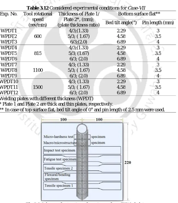
When joining plates of different thickness using the FSW process, the published literature reported a maximum difference of 1 mm between the adjacent plates.
Introduction
Material Preparation
Experimentation
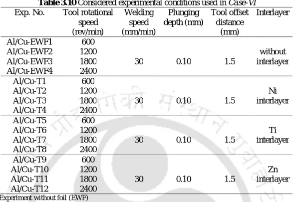
By changing four process parameters, a total of twelve experiments are performed for analysis of mechanical and metallurgical properties of the joints. The schematic of the workpiece plates and the interlayer foil position is shown in Fig.
Tensile Test
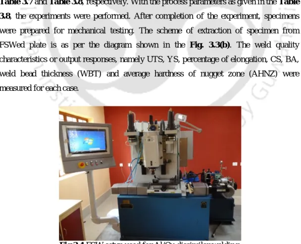
From each experimental condition, two tensile test specimens and one specimen each for fatigue test, bending/bending test, impact test, microhardness test and macro/microstructure analysis were extracted as shown in the diagram shown in Fig.3.8. Joint photographs of flat welded bottom surface samples for both single and double passes are shown in Figure 3.9. UTS and YS are measured on each of the weld samples and the percent elongation was measured on the same tensile test sample.
Hardness Test
For Al/Cu welded samples and Al/Al with different thickness, welded samples were measured at a force of 300 g for 10 s dwell time.
Compressive, Flexural and Bend Test
When the material is in a bending state, the outermost layer of the material experiences the maximum stress. However, if the same material is subjected to tensile forces only, then all layers in the material are under the same stress and failure will begin when the weakest layer reaches its ultimate tensile stress value. The bend test is a simple and inexpensive qualitative test to evaluate the strength and ductility of the material.
Fatigue Test
Impact Test
Macro/Microstructure by Optical Microscope (OM)
Scanning Electron Microscope (SEM)
Field Emission Scanning Electron Microscope (FESEM)
Some of the fractograph samples are observed by the FESEM with much higher resolution to observe the intergranular and transgranular fracture to the surface. The FESEM-EDX analysis was performed on the fracture surface of the tensile tested specimen to observe the type of IMCs formed at the fractured area. In some set of experiments, the FESEM-EDX analysis was performed on the cross-section of the weld center to detect various IMCs formed by the alloy element at the weld zone.
X-ray Diffraction (XRD)
3D complete and fractured grains at respective fracture states are observed in different zones of the weld for respective sets of experiments. There are various methods for phase analysis and the methods considered for the present work are FESEM equipped with EDX followed by line scanning and elemental mapping. The purpose of this analysis is to detect the formation of different phases in the NZ area, IMCs and compared with EDX analysis.

FSW of AM20 Magnesium Alloy
Introduction
Optimization of Process Parameters by Taguchi Grey Relational Analysis
- Taguchi Grey Relational Analysis
- Implementation of Taguchi GRA for Selection of Optimal Parameter
- Strategy-1: All the output responses are taken as “Higher the better”
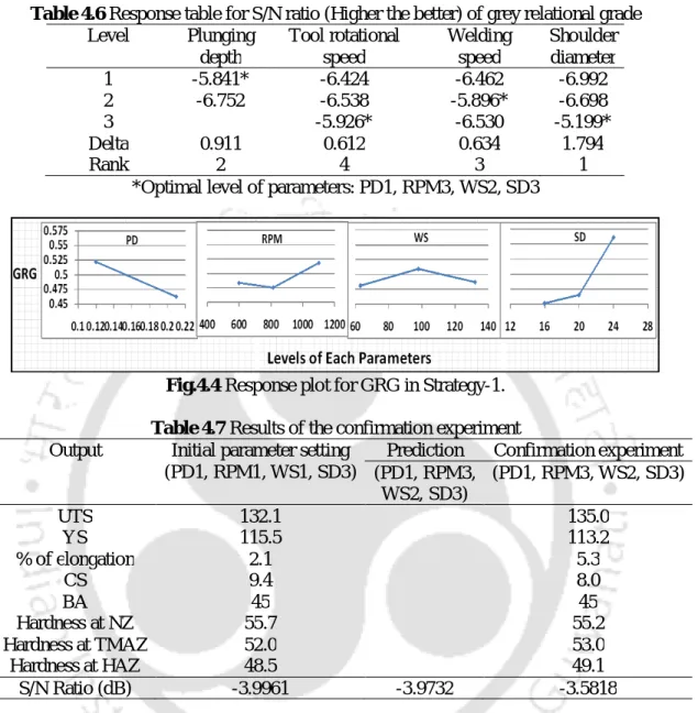
For optimization, two strategies were considered: Strategy 1 – all quality parameters were considered as 'the higher the better', that is, the goal of Strategy 1 is to maximize all quality parameters. Table 4.4 and Table 4.5 show that the contributions of all design parameters remain the same. Based on the average effect plot (Figure 4.4), it appears that the optimal parameter combination for this multi-criterion optimization problem is at factor levels 1, 3, 2, and 3. The multi-criterion optimization problem is at levels 1 , 3, 2 and 3 of the factors of plunge depth, tool rotation speed, welding speed and shoulder diameter, respectively.
- Strategy-2: Some output responses taken as “Higher the better” and other are taken as “Lower the better”
- Effect of Individual Parameters on Microstructure and Mechanical Properties
- Mechanical Properties Analysis
- Thermal Analysis
- Fractured Surfaces and Fractographs
- Metallographic Analysis
- a) which leads to proper grain mixing and refinement. With increasing shoulder diameter tool-workpiece contact area increases which leads to higher frictional heat
- Correlation of Mechanical Properties with Grain Size
- Summary
It was also found that the hardness of the NZ is significantly higher compared to TMAZ, HAZ and BM. The mean grain size of the NZ is also significantly affected by the variation in diving depth. The effect of grain size, due to variation in tool rotation speed, on the mechanical properties of the weld is shown in Fig.
FSW of AM20 Magnesium Alloy with Metallic Foil Alloying
Introduction
Therefore, the idea of reducing brittleness and improving ductility with improved mechanical properties of the FSWed Mg joint can be achieved by using Al and Zn as alloying elements. The purpose of this study is to focus on the effectiveness of individual alloying using Al or Zn on Mg matrix to improve the mechanical and microstructural properties of FSW joint. An Al and Zn interlayer is added to the joint interface before the start of the welding process to promote adhesion during welding and improve the properties of the welded plates.
Analysis of the Experimental Results
- Tensile Properties
- Fracture Behavior and Fractographs
- Flexural and Bending Properties
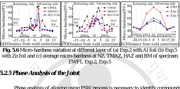
- Micro-hardness Distribution
- Phase Analysis of the Joint
- XRD Analysis
- Elemental Distribution (Mapping and Line Scan)
- Metallographic Analysis
- Specimen EWF1
- Effect of Rotational Speed and Alloying on Grain Size
However, in the case of Exp.5, the maximum hardness of the weld zone is 71 HV as shown in figure. The exact view of the NZ in the case of Exp.2 is shown in the figure. Similarly, the line scan and elemental mapping were performed on the NZ. of the sample Exp.5 as shown in Fig.
Summary
The average grain size of NZ with Al and Zn alloying element is 25% and 65% finer than NZ for welds without alloying elements. The alloying element Zn shows finer grains in NZ due to local melting of Zn. The local melting of Zn caused a decrease in temperature and leads to a higher effective cooling rate at NZ, resulting in smaller grain sizes.
Optimization and Influence of Process Parameters in FSW of Al/Cu Dissimilar Joint
Introduction
Optimization and influence of process parameters in FSW of Al/Cu dissimilar Joint optimized parameters in mind, part of this research work is dedicated to developing effective multi-objective optimization techniques for dissimilar Al/Cu FSW processes. Section 6.2 (Case IV mentioned in Chapter 3) contributes to the optimization of the quality of multiple welds using the Fuzzy-grey-Taguchi analysis technique of Al/Cu dissimilar joints. Section 6.3 (Case V as mentioned in Chapter 3) contributes to the effects of individual process parameters on the mechanical and metallurgical properties of Al/Cu dissimilar FSWed joints.
Hybrid Fuzzy-Grey-Taguchi Method for Optimization of Process Parameters
- Implementation of Fuzzy-Grey-Taguchi Method
- Fuzzy Inference Process
- Fuzzification
- Fuzzy Rule Base
- Selection of Optimal Parameters Setting
- Analysis of Variance
- Verification of the Predicted Result
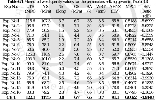
The output of the inference system, i.e. the multi-performance characteristic index (MPCI), is divided into six fuzzy levels, namely very low (VL), low (L), between low and medium (LM), between medium and high (MH ), high (H) and very high (VH). The effect of control parameters on the ratios of the MPCI values was calculated and shown in Table 6.3. The predicted / ratio, using the optimal level of the design parameters, is calculated using Eq.
Influence of Individual Process Parameters on Mechanical and Microstructures Properties
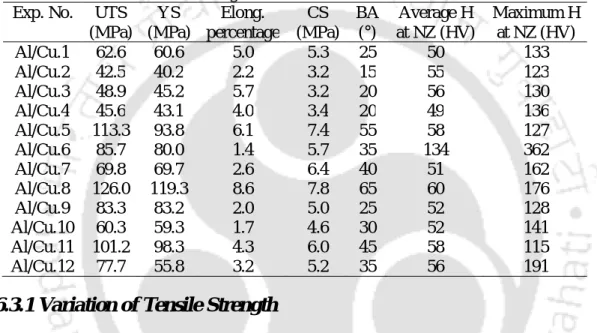
- Variation of Tensile Strength
- Fracture Behavior and Fractographs
- Compressive Strength and Bending Angle
- Micro-hardness Distributions
- Phase Analysis of Al/Cu Weld
- Material Flow during Al/Cu FSW
- General Feature of Microstructure
- Analysis of NZ Microstructure and Grain Size
The SEM image of the tensile tested fracture surface of sample Al/Cu.8 is shown in the figure. The size of grains on the NZ of experiments Al/Cu.1‒6 is shown in the figure. From the grain size analysis, it was found that the sample Al/Cu.8, as shown in fig.
Summary
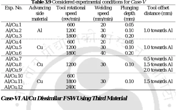
The effects of the tool offset were investigated from the experiments Al/Cu.5 and Al/Cu.7‒9. From this set of experiments it was observed that Al/Cu.8 gives the highest tensile strength and hardness value. This is one of the reasons for the improved tensile strength for the sample Al/Cu.8.
Al/Cu Dissimilar FSW Using Third Material
Introduction
Analysis of Experimental Results
- Variation of Tensile Strength
- Fracture Behavior and Fractographs
- Flexural Properties and Bending Angle of the Joints
- Micro-hardness Distribution of Joints
- Phase Analysis of the Joint
- Material Flow, Flow Control by Interlayer and Microstructural Analysis
Figure 7.5 (a) Variation of bending stress without and with interlayer, (b) variation of bending angle without and with interlayer, (c) Al/Cu-T10 bending specimen. A detailed view of the NZ in the case of Al/Cu-EWF2 is shown in Fig. Ti interlayer, (c) junction interface and formation of smaller IMCs, (d) junction interface and thin interlayer, (e) end point of Ti interlayer, (f) NZ on Al side, 38 μm, (g).
Summary
Phase analysis revealed that the Al/Cu IMCs are hindered by Ni and Ti interlayer. Thin, continuous and uniform IMCs are observed in the case of Zn interlayer with improved mechanical and metallurgical properties. The macro/microstructural analysis revealed that the flow of IMCs is controlled in the case of Ti interlayer and thin, continuous and uniform IMCs with finer grains in the NZ with Zn interlayer.
Dissimilar Thickness Al Alloy Weld by Single/Double Pass FSW
Introduction
Analysis of the Weld
- Tensile Strength Analysis
- Flexural Strength and Bending Angle Analysis
- Impact Strength Analysis
- Fatigue Life Analysis
- Temperature Analysis
Figure 8.3 (a) Tensile tested fractured surface of SPBF specimen, (b) enlarged view of (a), (c) DPBF specimen with cup on first part of fractured surface, (d) cone shape on opposing surfaces, (e) tensile fractured surface of SPTF samples and (f) magnified. However, none of the DPBF samples were fractured by the same impact energy shown in the figure. It was also found that the temperature of the advancing side is 25°C to 40°C higher compared to the retreating side shown in the figure.
Metallographic Analysis
- Material Flow and Feature of Microstructure at Various Zones
- SPBF Specimen
- DPBF Specimen
- SPTF Specimen
- Analysis of NZ Microstructure and Grain Size
- Hardness Analysis
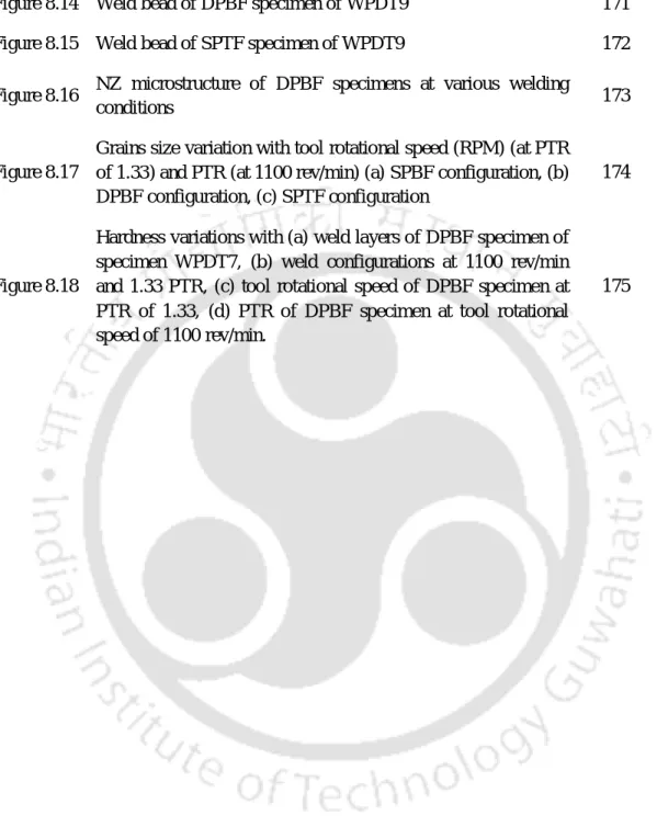
It was observed that the difference in material flow in joints with different thicknesses on both sides of the NZ changes the onion-ring pattern (Fig. 8.14b-c). The difference is due to the generation of more than one onion ring (Fig. 8.14a-c) in the same joint with non-uniform structure. Fig.8.15 (a) Weld bead of SPTF sample of WPDT9, (b) NZ microstructure, (c) TMAZ microstructure on advancing side, (d) HAZ microstructure on advancing side, (e) flow of.