First, a geometrically nonlinear vibration analysis of smart isotropic FG plates (ceramic-metal) with a heated plate surface is performed in the frequency domain. The analysis is further extended to investigate the effect of FG plate surface temperature on the control performance of PFRC actuator when used in the form of ACLD layer.
LIST OF FIGURES
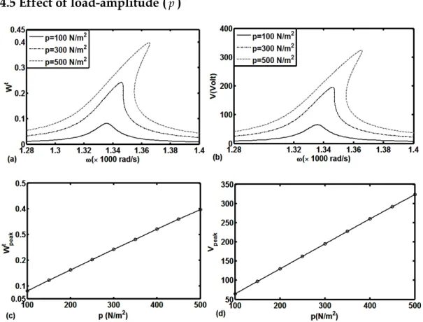
6.3 (a) Nonlinear frequency responses of the overall symmetrical CGLCP (n 1)/CLCP and (b) the corresponding variations of the control voltage (kd 100); variations of (c) peak amplitude (Wpeak) of the frequency response curve and (d) the corresponding control voltage (Vpeak) with the load amplitude (p). 6.4 (a) Nonlinear frequency responses of the overall asymmetric CGLCP (n 1)/CLCP and (b) the corresponding variations of the control voltage (kd 100); variations of (c) peak amplitude (Wpeak) of the frequency response curve and (d) the corresponding control voltage (Vpeak) with the load amplitude (p).
LIST OF TABLES
NOTATIONS
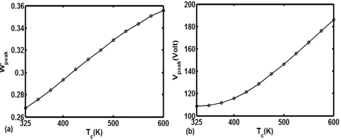
S Harmonic terms represented in matrix form Tc Ceramic rich surface temperature of the FG plate Tm Metal rich surface temperature of the FG plate. Wt Maximum value within a period of time at a certain frequency Wpeakt Peak point of the response curve.
INTRODUCTION
Introduction
This GFRC concept provides graded material properties within the fiber reinforced composite panel, which certainly improves the performance of composite structures in various aspects such as reduction of thermal stresses, reduction of stress concentration, etc. A brief review of the application of piezoelectric fiber reinforced composite (PFRC) and active limited layer damping (ACLD) smart structures.
Functionally graded materials (FGMs)
- Linear static analysis of FG plates
- Nonlinear static analysis of FG plates
- Linear dynamic analysis of FG plates
- Nonlinear dynamic analysis of FG plates
Many studies on the linear thermoelastic behavior of FG plates have been reported in the literature. Alibeigloo (2010) presented analytical solutions for the three-dimensional thermoelastic behavior of simply supported rectangular FG plates.
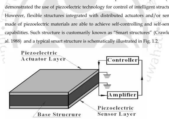
Smart structures
- Smart FG structures
Huang and Shen (2004) analyzed the nonlinear vibration responses of a smart FG plate under the thermal environment. Behjat and Khoshravan (2012) performed nonlinear static and free vibration analyzes of smart FG plates under different sets of mechanical and.
Piezoelectric composites
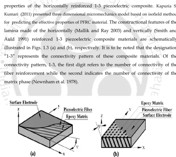
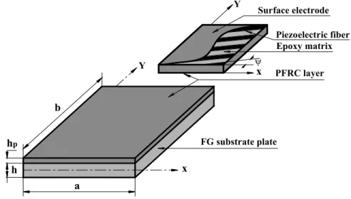
The structural characteristics of a lamina made of horizontally (Mallik and Ray 2003) and vertically (Smith and Auld 1991) reinforced 1-3 piezoelectric composite materials are shown schematically in fig. In the case of a lamina of vertically reinforced 1-3 piezoelectric composite material (Smith and Auld 1991), the piezoelectric fibers are aligned in the vertical plane so that they are coplanar with the xz plane or the yz plane, while they may be inclined. in the vertical plane with the vertical direction (z) forms an angle .
Active constrained layer damping
Ray (2006) investigated the performance of PFRC as a material in the confining layer of ACLD treatment for active control of FG plates. They also investigated the effect of piezoelectric fiber orientation angle in the active confining PFRC layer on the damping properties of the overall FG plates.
Graded fiber-reinforced composites
In this study, a symmetrical FG fiber laminated composite beam with variable FVF along the thickness direction is analyzed to demonstrate the advantage of creating graded material properties for thermal deflection control of the laminated beam. This analysis revealed the effect of different fiber orientation on the mechanical responses of the structures.
Research motivation and objectives
In the aforementioned available studies on the design and analysis of structural behavior of graded fiber reinforced composite laminate/laminate, the graded material properties are estimated using standard micromechanics theories. This issue of changing laminate stiffness is not addressed in the same study (Fu et al. 2010) while obtaining continuous variations of stresses/material properties in the thickness direction.
Contributions
A microstructure for a graded orthotropic fiber-reinforced composite lamina with variable fiber volume fraction (FVF) in the thickness direction is designed and its (lamina) effective graded elastic properties are evaluated using a finite element method in conjunction with an available micromechanics model for FG composites (Reiter and Dvorak f) A new lamination scheme is proposed in the design of composite laminates using conventional and graded orthotropic fiber-reinforced composite inserts. The objective in this proposed lamination scheme is to achieve continuous stress/material property changes through the thickness while maintaining sufficient laminate stiffness and stress within their allowable values. g).
Dissertation overview
In this chapter, a new lamination scheme for the design of graduated laminated composite plates is proposed. The new lamination scheme is demonstrated by the conversion of a conventional laminated composite sheet into a graduated laminated composite sheet.
HARMONICALLY EXCITED NONLINEAR VIBRATION OF HEATED FUNCTIONALLY GRADED PLATE INTEGRATED
Introduction
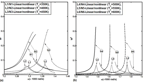
The ceramic-rich surface of the FG plate is considered to be exposed to a high temperature, while the metal-rich surface of the same is at room temperature. Based on von Karman's nonlinear stress-displacement relations, an incremental closed-loop finite element model of the overall smart FG plate is derived by assuming its (plate) periodic motion.
Problem statement and incremental finite element formulation
- Implementation of harmonic balance method (HBM)
- Smart damping
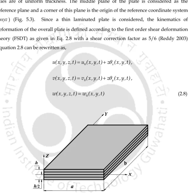
A state of deformation of the overall plate can be defined in terms of the generalized displacements (u0, v0, w0, x and y) which can also be expressed in the form of a generalized displacement vector as follows,. 2.8), the von Karman nonlinear strain displacement relations can be expressed as, . For the vibration of the overall plate, the first variation of its total kinetic energy (Tk) can be written as follows,.
Solution methodology
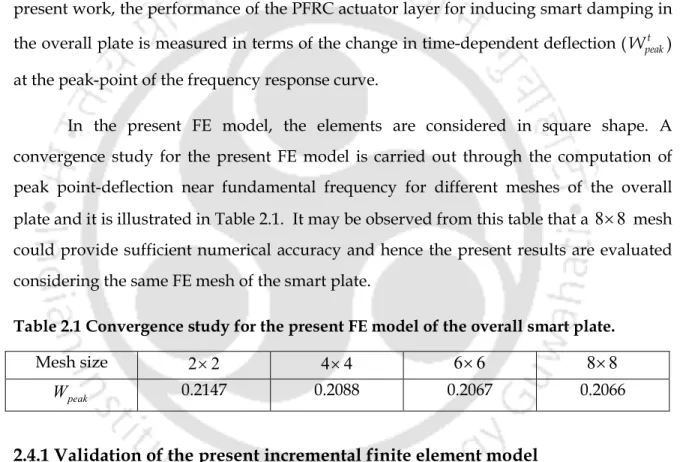
- Validation of the present incremental finite element model
- PFRC layer on metal/ceramic rich surface of substrate FG plate
- Effect of volume fraction index ( n ) of FG substrate plate
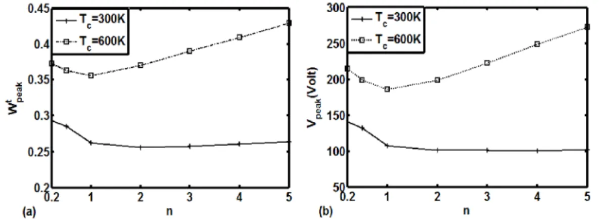
The corresponding variations in the required control voltage over the thickness of the PFRC actuator layer are also illustrated in Fig. 2.16(a) shows a decrease in the control authority of the PFRC actuator layer at a higher value of n.
Conclusions
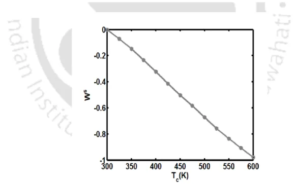
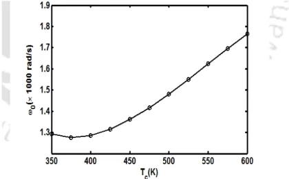
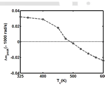
Normally, the fundamental vibration frequency of the assembled FG plate decreases as its temperature increases. The fundamental vibration frequency of the assembled FG plate decreases with the increase of the metal volume fraction in the FG substrate.
Chapter 3
- Introduction
- Problem Statement and Incremental Finite Element Formulation
- Implementation of GHM model
- Implementation of harmonic balance method (HBM)
- Implementation of control strategy
- Numerical results and discussions
- Validation of the present incremental finite element model
- Effect of volume-fraction index ( n ) of substrate FG plate
- Effect of fiber volume fraction ( v f ) in constraining
- Effect of fiber orientation angle ( ) in constraining PFRC layer For constant values of control gain
- Effect of substrate FG plate thickness ( h )
- Conclusions
Next, these equations are expressed in the frequency domain assuming periodic motion of the assembled plate. The damping in the assembled plate caused by the ACLD layer is measured in relation to the parameter Wpeakt (section 2.4).
SIZE AND LOCATION OF PFRC/ACLD PATCH FOR EFFECTIVE CONTROL OF NONLINEAR VIBRATION OF
Introduction
Numerical procedure for effective size and location of PFRC/ACLD patch
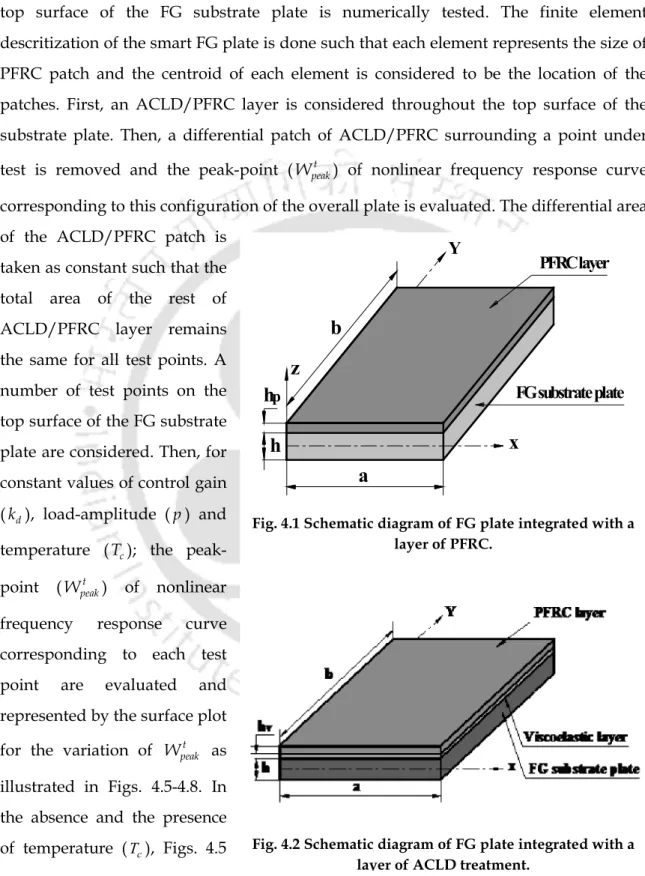
First, the ACLD/PFRC layer over the entire top surface of the substrate plate is considered. Several test points on the top surface of the FG substrate plate are considered.
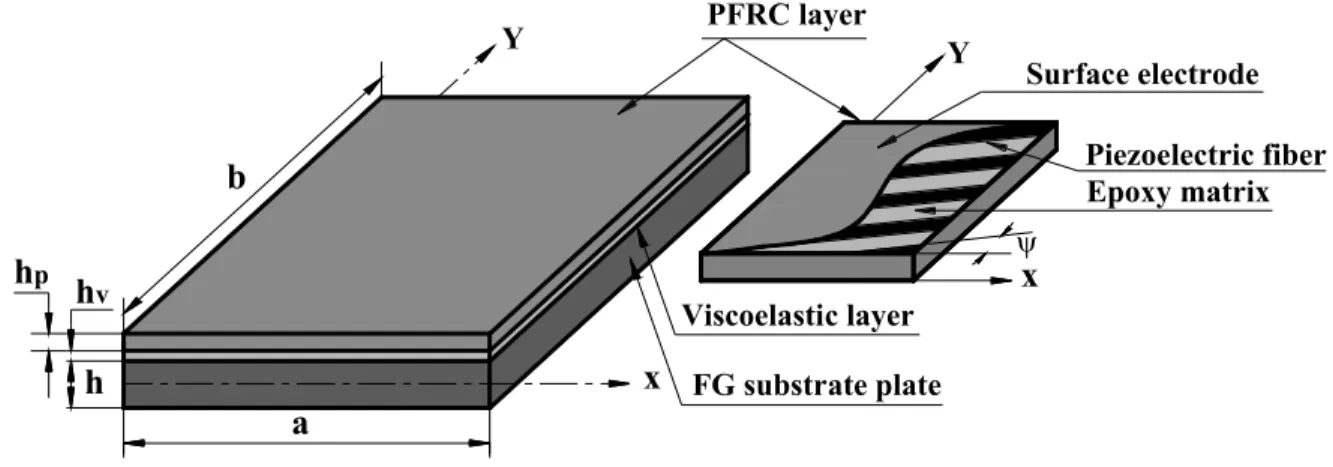
PFRC layer
FG substrate plate
Viscoelastic layer
The differential patch of ACLD removed surrounding a typical test point
Conclusions
This chapter describes a numerical procedure to estimate the size and location of the PFRC/ACLD patch on the top surface of the FG slab foundation for effective vibration control of the entire FG slab. But the effective size of the same (patch) may change due to the presence of temperature.
DESIGN OF LAMINATED COMPOSITE PLATES USING GRADED ORTHOTROPIC FIBER-REINFORCED
Introduction
The new lamination scheme is demonstrated by converting a conventional laminated composite plate (CLCP) into a conventional graded laminated composite plate (CGLCP). A bending analysis of these plates (CLCP and CGLCP) is performed to investigate the suitability of current conversion of a CLCP by the corresponding changes in laminate stiffness, stress mismatch at interlaminar surfaces, stress concentration and maximum values of stress in the laminate.
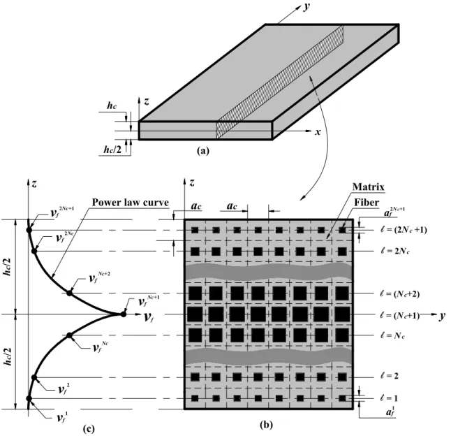
Present graded composite lamina
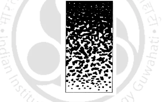
Although the use of a power law ensures a continuous variation of the FVF along the thickness (z) direction, the FVF of a layer is considered as the point on the power law curve where the center line of this layer intersects (Fig. Since the identical square cross-section (ac) of all fiber-matrix bundles is considered within the composite lamella, the variation of FVF between the layers is achieved by the variation of the cross-section of the fibers through the individual layers.
FiberMatrix
Graded effective elastic properties
Then, the effective properties of each homogeneous layer are derived from the volume-averaged properties of the RV. Similarly, the volume average strain vectors ({ }f ,{m}) for the fiber and matrix phases within a layer () can be expressed in terms of the volume average stress vector ( { }ε ) of RV as,.
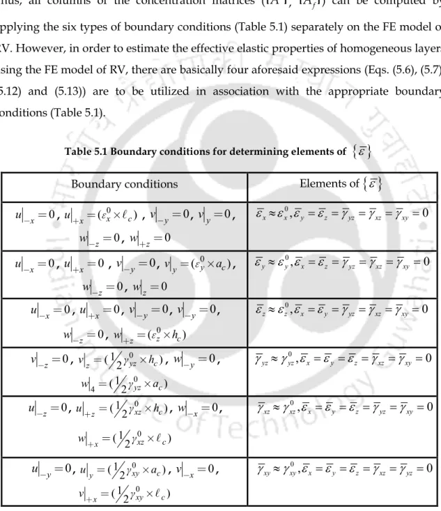
Finite element model of RV
After composing the elementary equations (Eq. 5.23)) in the global space, we can obtain a global expression for the first variation of the deformation energy as,. Accordingly, the generalized displacement vector (Eq. 2.9)) within a typical element can be written according to Eq.
Numerical results and discussions
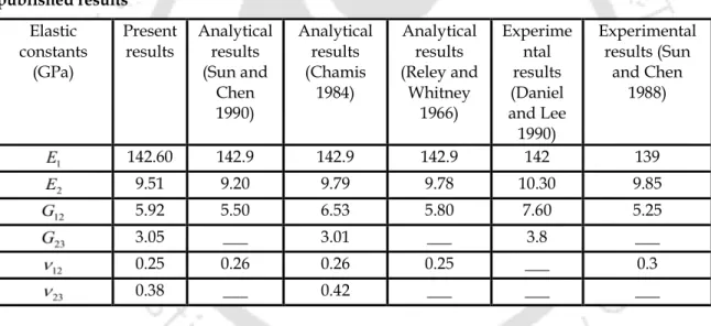
- Effective elastic properties of graded composite lamina
- Verification of FE model of laminated composite plate
- Bending responses of GLCPs
In the aforementioned fiber-reinforced composite layer (Fig. 5.1), the variation of FVF is considered to be symmetric with respect to the mid-plane (z0 ) of the layer. For two different loads (p = 10 N/m2, 5 kN/m2) corresponding to the linear and nonlinear bending deformations of the symmetric CGLCP, the stress distributions (x,y) along the laminate thickness are illustrated in Fig.
Conclusions
The numerical analysis of the effective properties of graded composite lamina shows identical nature of variation of each elastic coefficient as it is (nature) for the variation of corresponding FVF. It is observed that the number of composite layers within a given thickness of lamina does not have much effect on the nature of variation of any effective elastic coefficient.
Introduction
First, an incremental finite element model of smart CGLCP is derived for its dynamic analysis in the frequency domain. The corresponding changes in active attenuation caused by the ACLD layer are also illustrated through the same numerical results.
Incremental finite element formulation
Thus, the layerwise FSDT as illustrated in Eq. 3.3) is considered for determining the kinematics of its deformation (laminated plate) with a shear correction factor of 5/6 (Reddy 2003). Thus, the various sub-matrices in Eq. 6.4) are defined by the same expressions as those given in Eqs.
Numerical results and discussions
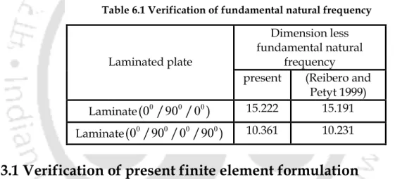
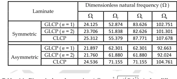
- Verification of present finite element formulation
- Free vibration response of CLCP/CGLCP
The methodology for solutions of this form of equations is described in Section 2.3 and it is also currently followed in the evaluation of the non-linear frequency responses of the graded laminated composite plate integrated with an ACLD layer. Similar to the previous numerical analysis (Section 3.3), the maximum value of W is considered to be less than five terms (r1, 2, 3) of Fourier series are considered for the solutions.
Han and Petyt
- Effect of power law exponent (n)
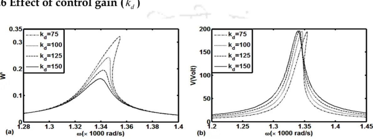
- Effect of control gain ( k d )
- Effect of viscoelastic-layer thickness ( h v ) in ACLD arrangement
- Effect of fiber-orientation angle ( ) in PFRC layer
- Conclusions
This may be mainly due to the decrease in overall plate stiffness after a CLCP is converted to a CGLCP. However, for any of the laminates, the variations of the peak amplitude for two different values of control gain (kd) show that the active limiting layer (PFRC) effectively increases the overall damping.
CONCLUSIONS
General conclusions
Conclusions
- Specific conclusions