저작자표시-비영리-변경금지 2.0 대한민국 이용자는 아래의 조건을 따르는 경우에 한하여 자유롭게
l 이 저작물을 복제, 배포, 전송, 전시, 공연 및 방송할 수 있습니다. 다음과 같은 조건을 따라야 합니다:
l 귀하는, 이 저작물의 재이용이나 배포의 경우, 이 저작물에 적용된 이용허락조건 을 명확하게 나타내어야 합니다.
l 저작권자로부터 별도의 허가를 받으면 이러한 조건들은 적용되지 않습니다.
저작권법에 따른 이용자의 권리는 위의 내용에 의하여 영향을 받지 않습니다. 이것은 이용허락규약(Legal Code)을 이해하기 쉽게 요약한 것입니다.
Disclaimer
저작자표시. 귀하는 원저작자를 표시하여야 합니다.
비영리. 귀하는 이 저작물을 영리 목적으로 이용할 수 없습니다.
변경금지. 귀하는 이 저작물을 개작, 변형 또는 가공할 수 없습니다.
February 2019 Master’s Degree Thesis
A study of camera-integratable inverted-F antenna for
capsule endoscope
Graduate School of Chosun University
Department of IT Fusion Technology
Se Woong Kim
[UCI]I804:24011-200000267311
A study of camera-integratable inverted-F antenna for
capsule endoscope
카메라와 집적이 가능한 캡슐형 내시경용
inverted-F 안테나에 대한 연구
February 25, 2019
Graduate School of Chosun University
Department of IT Fusion Technology
Se Woong Kim
A study of camera-integratable inverted-F antenna for
capsule endoscope
Advisor : Prof. Youn Tae Kim
This thesis is submitted to The Graduate School of Chosun University in partial fulfillment of the
requirements for the Master’s degree
November 2018
Graduate School of Chosun University
Department of IT Fusion Technology
Se Woong Kim
Table of Contents
Table of Contents ··· v
List of Tables ··· vi
List of Figures ··· vii
Acronyms ··· ix
요약 ··· x
Abstract ··· xi
I. Introduction ··· 1
II. Previous methods ··· 2
A. Purpose ··· 2
B. Capsule endoscopy ··· 2
C. WBAN system ··· 5
D. Planar inverted-F antenna ··· 8
E. Smith chart ··· 10
III. Proposed structure ··· 11
IV. Experiment and result ··· 14
A. Simulation ··· 14
B. Performances of fabricated antenna ··· 17
V. Conclusion ··· 21
References ··· 23
List of Publications ··· 26
Acknowledgement ··· 30
Table 1 Application service of WBAN ··· 6
List of Tables
Figure 2.1 Capsule endoscope and internal components in
Mayo clinic ··· 3
Figure 2.2 Capsule endoscopy classification by transmission method ··· 4
Figure 2.3 The concept of WBAN ··· 5
Figure 2.4 Configuration of WBAN healthcare system ··· 7
Figure 2.5 The basic structure of PIFA ··· 9
Figure 2.6 The principle of miniaturization of PIFA ··· 9
Figure 3.1 Structure of the proposed antenna ··· 11
Figure 3.2 Structure of the camera-integratable inverted-F antenna ··· 12
Figure 4.1 The antenna inside a capsule module ··· 14
Figure 4.2 Simulated return losses with the LEDs and camera ··· 16
Figure 4.3 Simulated return losses with the PEC cylinder ···· 16
Figure 4.4 Fabricated antenna ··· 17
List of Figures
Figure 4.5 Assembling parts and antenna assembled with the
capsule module ··· 17
Figure 4.6 Measurement setup to measure return loss ··· 18
Figure 4.7 Measured return loss ··· 19
Figure 4.8 Radiation pattern at
∘··· 20
Figure 4.9 Radiation pattern at
∘··· 20
RF Radio Frequency
HBC Human Body Communication
WBAN Wireless Body Area Network
PIFA Planar Inverted-F Antenna
CST Computer Simulation Techonology
Acronyms
요 약
카메라와 집적이 가능한 캡슐형 내시경용 inverted-F 안테나에 대한 연구
김세웅
지도교수: 김윤태 교수 Ph. D.
조선대학교 대학원 IT 융합학과
캡슐형 내시경은 일반 내시경을 대신하여 고통이 없으며 쾌적한 소장 검사 방법이 다. 기존 상용화된 캡슐의 지름은 11mm, 길이는 23mm 내외로 매우 소형이다. 또한 캡슐 내부에는 영상 기록장치, 무선 송신부, 배터리가 위치하고 이러한 전자 소자들 이 차지하는 공간을 고려해 최소화된 안테나 구조가 요구된다.
2.4 GHz의 ISM 무선 통신 대역에서 동작하는 캡슐형 내시경용 안테나를 제안한 다. 상용 캡슐의 크기를 고려하여 안테나를 설계하였다. 제안된 안테나는 카메라의 영상 촬영을 방해하지 않기 위한 구조로 설계되어 카메라와 동일한 면에 집적이 가 능하다. 그리고 캡슐 내부에 위치하는 다양한 전자 소자들에 의한 커플링 간섭으로 데이터 손실, frequency shift, mismatching을 막기 위해 차폐가 가능한 구조를 가진 다. 설계한 안테나의 인체 매질 환경에서의 시뮬레이션과 실제 제작 후에 제작된 안 테나의 전기적 특성과 방사 패턴을 측정하기 위해 인체 팬텀은 초순수로 구성하였 다. 설계한 안테나는 평균과 최대 이득이 각각 –7.99, -3.13 dBi이며 전방향 방사 패 턴을 보인다. 또한 2.386 GHz에서 151 MHz의 대역폭으로 동작한다. 따라서 캡슐형 내시경의 양방향 촬영과 넓은 시야각 확보를 통해 정확한 질병 진단이 가능하다.
Abstract
A study of camera-integratable inverted-F antenna for capsule endoscope
Se Woong Kim
Advisor : Prof. Youn Tae Kim, Ph.D.
Department of IT Fusion Technology, Graduate School of Chosun University
Capsule endoscopy is a painless and more pleasant experience alternative to the usual endoscopic examination of the small intestine. A capsule endoscope consists of a subminiature camera, a lens, a light emitting diode, an instrument for recording pictures, a wireless transmitter, and a battery. The capsule endoscope captures images while moving through the digestive tract, and the image is transmitted to the outside of the human body through an antenna.
This paper presents an inverted F antenna for a capsule endoscope. This antenna operates in the 2.4 GHz ISM band. The proposed antenna has high gain and accomplishes miniaturization by employing an inverted-F antenna structure.
The proposed antenna is also designed to have an electric shield to prevent coupling with other electronic components at both sides of the capsule endoscope.
In addition, it is designed to avoid interference with the view of the camera. A human phantom consisting of de-ionized water is used for simulation and to measure the antenna performance. The designed antenna has average and maximum gain of –7.99 and –3.13 dBi. And the center frequency and the bandwidth are 2.386 GHz and 151 MHz. Therefore, accurate disease diagnosis in
the digestive tract with a capsule endoscope using the proposed antenna is possible at wide viewing angles.
I. Introduction
Capsule endoscopy is a painless and more pleasant alternative to the usual endoscopic examination of the small intestine. A capsule endoscope consists of a subminiature camera, a lens, a light emitting diode, an instrument for recording pictures, a wireless transmitter, and a battery. The capsule endoscope captures images while moving through the digestive tract, and the image is transmitted to the outside of the human body through an antenna [1]-[5]. For the image transmission, a transmitting antenna is required.
A capsule endoscope has a limited space and size; hence, the transmitting antenna should be designed to take minimum space. For this, various microstrip line antennas positioned on the surface of a capsule endoscope have been proposed [6]-[11]. Such a surface antenna, however, has a high complexity because the antenna should be installed on a curved surface.
Instead of the surface, a transmitting antenna can be installed inside a capsule endoscope [12]-[17]. Such a modular antenna, however, obstructs the view of the camera and therefore, should be installed on the opposite side of the camera. In addition, the modular antenna can experience signal loss or frequency shift due to coupling with other electrical components composing the capsule endoscope. Therefore, it is essential that the modular antenna is electronically shielded and does not interfere with the view of the camera.
This paper proposes an inverted-F antenna that is printed on a ring-shaped substrate. The proposed antenna has a structure that helps avoid the obstruction of the view of the camera while simplifying the fabrication process of the antenna. As a result, the antenna can be integrated with a camera for the capsule endoscope at the same side. This will help in accurate diagnosis of diseases by bi-directional photographing and securing of a wide viewing angle without power consumption for direction control. The antenna is designed to prevent the electrical coupling with the other components of the capsule endoscope. The proposed antenna operates at the 2.4 GHz
industrial, scientific, and medical (ISM) radio band. The antenna is designed considering the effects of light emitting diodes (LEDs) and the camera module on the antenna performance.
II. Previous methods
A. Purpose
This study presents a new antenna structure for transmitting image data captured by a capsule endoscope to an external image acquisition device.
B. Capsule endoscopy
The capsule endoscope includes a small camera, a battery, a signal processing circuit, and a wireless transmission circuit in a capsule having a volume of about 4cc. The capacity of the battery is not as large as 60 mAh or less. With this small battery capacity, the capsule endoscope should be taken continuously for more than 8 hours.
In the medical field, endoscopy is used for examination and surgery.
Typically, there is an upper digestive tract endoscopy that examines the esophagus, gastric, and duodenal with the endoscope inserted through the mouth or nose, and a colonoscopy that examines bowel disease with the endoscope inserted through the anus.
The small intestine which is long and twisted proceeds a digestive process through repeated contract and relax. Although it is not appropriate to use conventional endoscopes, a method of inserting an endoscope with a balloon into the mouth or anus and fixing the small intestine has been introduced.
However, this method is too difficult for patients because it takes too long.
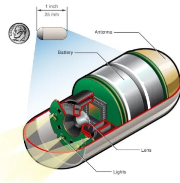
Figure 2.1. Capsule endoscope and internal components in Mayo clinic.
A capsule endoscope can solve this problem. As shown in figure 2.1, the capsule endoscope is a capsule-shaped endoscope. It consists of a camera (image sensor) that observes the inner wall of the digestive tract, a light emitting diode (LED) for photographing illumination, a wireless communication circuit, a signal processing circuit, an antenna, and a coin cell battery.
A person who is examined by a capsule endoscopy has a receiver on the abdomen. Then swallow the capsule endoscope with water. The capsule endoscope passes through the esophagus, stomach, and duodenum to the small intestine. The capsule endoscope continues to photographing until it reach the small intestine. The capsule endoscope continuously transmits the photographed image to the outside. The received signal is stored as image data through an external acquisition device. It is also possible to observe photographed pictures in real time.
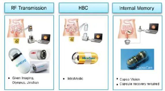
Figure 2.2. Capsule endoscopy classification by transmission method.
Figure 2.2 shows a method of transmitting image data stored in the capsule endoscope to the outside [18]. The transmission method includes an RF transmission method, a human body communication method, and an internal memory method. The RF transmission method and the HBC method transmit the images taken in the digestive tract immediately by the wireless communication, so there is no need to collect the capsule endoscope after use.
And capsule endoscopy has the advantage of confirming results quickly. On the other hand, the internal memory method require a cumbersome process of retrieving the capsule endoscope in order to obtain the image data stored in the memory, which is a drawback that it takes more time to check the result. Therefore, the capsule endoscope market occupies more than 90% of the capsule endoscope with wireless communication module.
However, a capsule endoscope with a wireless communication module can not be free from the problem of capsule size and transmission speed. Capsule endoscopy has many limitations on the size of the capsule for the patient to take it. If the size of the product is increased due to the wireless communication module, the product is inevitably out of the market. Therefore,
it is essential to design an optimized antenna for a small capsule size in order to miniaturize the capsule endoscope.
C. WBAN system
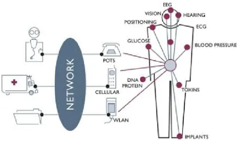
WBAN(Wireless Body Area Network) application system can be classified into the medical system which measures human vital signs such as blood sugar or electrocardiogram, transmits by wireless or operates devices in the human body, and the non-medical system which transmits voice or image data around the body or provides entertainment. Medical WBAN is classified into the wearable device which is attached to the body, and the implant device which is implanted to the body. WBAN technology measures vital signs inside and outside human body, accesses to the network through many devices, it is the wider concept service than existing health care service and this technology can provide true health care service.
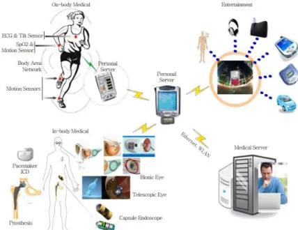
Figure 2.3. The concept of WBAN.
As shown in figure 2.3, WBAN is attached or implanted to the body according to the usage to collect vital information and utilized to the application of entertainment around human body. The coordinator forms Star topology with these devices to provide two ways communication, and controls and manages these devices. In addition, the coordinator is realized into the individual portable terminal type to provide various multimedia services that users want, and provides the function to collect, analyze and manage own health information .
The figure shows the structure WBAN service. It supports the interface for the medical service and non-medical service. The medical service is divided into the implantable type and the wearable type, the non-medical service provides the entertainment services such as voice, video stream delivery, data stream delivery and game. In order to provide these services, WBAN is implanted to human body for operation or performs the function to deliver personal medical service, so it needs the features such as Low latency, low power and high security.
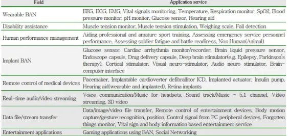
Table 1. Application service of WBAN.
WBAN should provide various features required to the application service, the application service submitted to CFA of IEEE 802.15.6 TG BAN in table
1 is proposed. When it comes to medical WBAN application service, about 40 services are suggested in the application fields such as wearable BAN, implantable BAN, remote control of medical device and hospital related fields, when it comes to non-medical WBAN, 20 services are suggested in the entertainment fields such as real time video, audio streaming, delivery of data file and stream and game.
Figure 2.4. Configuration of WBAN healthcare system.
Figure 2.4. shows WBAN health care system for the provision of healthcare service has the structure which is similar with the existing system. WBAN health care system needs the mobile service of WBAN unit focusing on the coordinator according to the movement of human in order to provide seamless service anytime and anywhere. In addition, WBAN system should be able to manage the subscription and withdrawal of individual devices commonly used such as training machine or weighing machine of fitness center according to the need [19]-[22].
WBAN health care system consists of WBAN which collects vital information, the medical server that collects, stores and manages vital
information and the network which interlocks them. It is composed of various WBAN devices focusing on WBAN coordinator. WBAN devices is implanted in human body or worn by human to play a role to collect vital information or operate devices.
WBAN services are provided through WBAN devices. WBAN coordinator plays a role to manage various WBAN devices, to collect vital information from WBAN devices and operate them. WBAN devices deliver the detected vital information to the personal server or the medical server, or detect vital information under the request of medical server or personal server, or operate devices.
Medical server performs the function to save, analyze and print the collected vital signs by managing the subscription to WBAN, the control of various WBAN devices, the type of data and the detection cycle of vital signs.
WBAN can figure out the present and past health condition of people through personal portable terminals because it provides mobility according to the trace of human. The personal portable terminal performs the function to collect the data from the device that subscribed WBAN system for analysis, and the function to check the health information stored in the remote medical server. Network should secure stable quality of transmission and provide the security technique in order to delivery personal medical data.
D. Planar inverted-F antenna
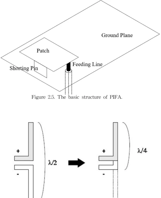
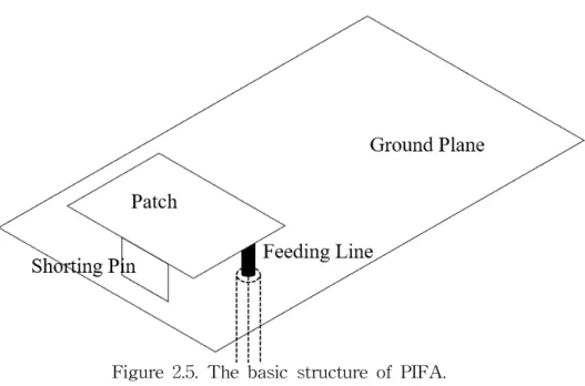
The Planar inverted-F antenna(PIFA) consists of a ground plane, a patch, a feed line, a shorting plate, or a shorting pin, as shown in Figure 2.5. The ground plane and the patch are connected by a shorting plate or a shorting pin, and the antenna is fed through the feed line.
Figure 2.5. The basic structure of PIFA.
Figure 2.6. The principle of miniaturization of PIFA.
The operating principle of the PIFA is that the patch is excited through the current feeding in the state where the rectangular patch is placed on the finite ground plane and serves as the radiation element together with the
ground plane. As shown in Figure 2.6, one side of the patch is shorted to the ground plane through a shorting pin, so that it can resonate at about 1/4 wavelength or less instead of 1/2 wavelength. Therefore, the size of the antenna can be reduced half or more. PIFA can be miniaturized, light in weight and easy to manufacture, so it is widely used as a small antenna.
E. Smith chart
The loop shaped inverted-F antenna was designed considering the basic principle of PIFA. The radiators of the designed antenna are connected to the feeding point as shown in the figure, and the radiators are located on the first and second layers of the multilayer substrate. The conductive line constituting the radiator has a resistance corresponding to the sum of the radiation resistance and the conductive resistance. The radiation resistance is a resistance representing the electric power of a radio wave from the conductive line. In the case of an antenna, the radiation resistance is known to be expressed by the following equation.
∙ ∙
(1)Where R is the radiation resistance, N is the number of turns of the conductive line, A is the area of the antenna, and Lambda is the wavelength at the operating frequency. On the other hand, the conductivity resistance due to the conductivity of the conductive line is expressed by the following equation according to the definition of the conductivity.
∙
(2)
Where Rc is the conductive resistance, σ is the conductivity, l is the length of the conductive line, and A is the area of the conductive line.
It is easy to use the smith chart for impedance matching when designing the antenna. In the Smith chart, the diameter of the circle starting from the right means the real part, and the curve spreading dispersedly means the imaginary part. For impedance matching, the thickness and length of the
copper line can be adjusted by moving the load impedance at the target frequency along the real and imaginary trajectories from the center of the circle to the point of 50 Ω.
III. Proposed structure
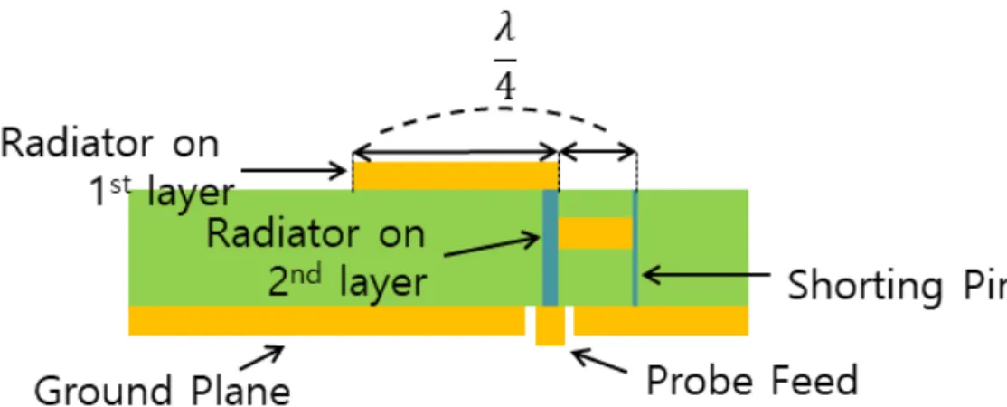
Figure 3.1. Structure of the proposed antenna.
Figure 3.1 shows the proposed antenna structure. This is a modified structure of an Inverted-F antenna that resonates at a quarter wavelength.
And it is easy to match the input impedance by adjusting the space between the shorting pin and the probe feed point. That being so, it can be manufactured as an small antenna for capsule endoscope. Also, in the fourth layer, there is a ground plane which effectively prevents interference of internal electronic elements of the capsule endoscope.
Capsule endoscopes are difficult to adjust their position and orientation themselves in the digestive tract. For this reason, the antenna should have a omni-directional radiation pattern in order to reliably transmit data to the external image acquisition device. Also, considering the complexity of the human body [23]-[24], the antenna should be designed to have wide bandwidth characteristics. The new structure of the inverted-F antenna
proposed in this study satisfies all the requirements mentioned above.
Simulations and measurement results that support this are explained in detail in Chapter 4.
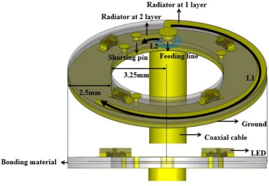
Figure 3.2. Structure of the camera-integratable inverted-F antenna.
Figure 3.2 shows the structure of the modified inverted-F antenna. The inverted-F antenna has the ring shaped and multi-layer substrate. The proposed antenna has the advantage that it is very easy to tune by adjusting the length of the radiator in first layer. The inverted-F antenna has a multilayered substrate of a ring shape. The radiator of the proposed antenna has a modified shape to fit the ring-shaped substrate. The proposed inverted-F antenna is located on the first and second layers. A copper radiator placed along the ring-shaped substrate and has a width of 0.5 mm.
A line of radiator connecting the shorting pin is located on the second layer.
The two radiators are connected through the via. A capsule endoscope has a camera and LEDs to illuminate inside the digestive tract. The LEDs could
affect the antenna performance. In Consideration of this, the LEDs and the copper pads for LEDs to be mounted were included in the design stage. The copper pads for the LEDs are connected to a ground plane through via respectively. The ground plane with copper is located on the fourth layer of the multi-layer substrate. A coaxial cable is used to feeding. The coaxial cable is connected to the ground plane at fourth layer. A signal is fed to the radiator on the first layer through the via. The feeding line connected to the radiator has a radius of 0.4 mm. Each via has a radius of 0.15 mm.
The substrate is made of Teflon with dielectric constant of 2.16, it is relatively low dielectric constant and it increase the radiation efficiency of the antenna. The inner radius is 3.25 mm and the width is 2.5 mm. The thickness of the layer is 0.25 mm. The bonding material between the bonded two substrates is located between the second and third layers. The inverted-F antenna is composed of two lines whose lengths are equal to L1 and L2, respectively, as shown in Fig. 3.1. In the proposed antenna, L1 and L2 are 21.4 mm and 1.5 mm respectively.
IV. Experiment and result
A. Simulation
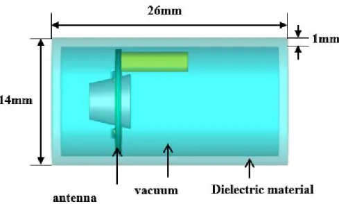
Figure 4.1. The antenna inside a capsule module.
Figure 4.1 shows the antenna installed inside a capsule module with a camera module. In the proposed antenna, the antenna substrate has a ring shape; hence, the camera module can be inserted inside the antenna and accordingly, the antenna and camera modules can be located on the same left side, as shown in Figure 4.1, while the other electronic components can be located on the right side. The capsule module has a dielectric constant of 3.15 and a thickness of 1 mm. In the proposed antenna, the antenna is located on the same side with the camera modules and LEDs; hence, the antenna's performance could be affected by the LEDs and the camera. To investigate this, the return losses of the designed antenna were simulated, with the camera module and LEDs added to the antenna sequentially. In the simulation, the camera module was modeled with homogeneous dielectric
material whose dielectric constant is 2.75; the LED was modeled with metal pads and a semiconductor substrate whose dielectric constant is 10.
The operating frequency of the antenna is greatly affected by the permittivity. Therefore, it is necessary to analyze the influence of the objects having the permittivity adjacent through the simulation. The effect on the dielectric can be confirmed by the return loss graph of the antenna. The camera module does not affect the return loss of the antenna as shown in figure 4.2. This is because, as shown in Figure 3.2, the antenna radiator has a separation distance from the inner ring of the antenna substrate and hence, the effects of the camera module is reduced. The LED, however, affects the return loss of the antenna. The center frequency decrease slightly when the LEDs are added to the antenna.
The center frequency of the antenna can be affected by other electronic components contained in the capsule endoscope. As in the previous simulation, the effect of the electronic components was simulated. In the simulation, the electronic component was simply modeled with a single perfect electric conductor (PEC) cylinder. The radius and length of the PEC cylinder were 4.75 and 7.2 mm, respectively. The PEC cylinder was placed on the right side of the antenna. The return losses were simulated varying the distance between the antenna and the PEC cylinder. Figure 4.3 shows the simulated return losses with PEC cylinder. In comparison with the absence of the PEC cylinder, the center frequency is not significantly affected by the PEC cylinder. This confirms that the ground plane on the fourth layer of the antenna substrate effectively prevents coupling between the antenna and the electronic components inside the capsule endoscope.
Figure 4.2. Simulated return losses with the LEDs and camera.
Figure 4.3. Simulated return losses with the PEC cylinder.
B. Performances of fabricated antenna
Figure 4.4. Fabricated antenna.
Figure 4.5. Assembling parts and antenna assembled with the capsule module.
Figure 4.4 and 4.5 show the fabricated inverted-F antenna, the assembling parts, and the assembled antenna, respectively. As shown in Figure 4.4, the
proposed antenna was fabricated on the multilayered substrate of the ring shape. Chip LEDs having a size of × respectively were mounted on the antenna surface. To assembling the fabricated antenna with the capsule module, the assembling parts shown in figure 4.5 were used. A connector board was used to connect the outside cable to the coaxial cable feeding the antenna. During the simulation, it was confirmed that the connector board does not affect the antenna's performance. The antenna should be fixed inside the capsule module for the antenna measurement. For this, the filler was located between the antenna and the connector board.
After assembling all the parts with the camera model, the assembled antenna was inserted into the capsule module. The capsule module has an outside cable for the antenna measurement. A waterproof tape was wrapped around the capsule module to prevent water leakage during the antenna measurement.
Figure 4.6. Measurement setup to measure return loss.
Figure 4.7. Measured return loss.
Figure 4.6 shows the measurement setup used to measure the return loss of the fabricated antenna. The capsule module including the fabricated antenna was placed at the center of the container. The antenna was located at a height of 75 mm from the bottom of the container. The container has a diameter and a height of 12.5 and 30 cm, respectively. The container was equipped with vertical and horizontal arms that were used to fix the position of the capsule module inside the container. After fixing the position of the capsule module, the container was filled with deionized water that was used as the human phantom. The return loss was measured using a vector network analyzer (VNA). Figure 4.7 shows the measured return loss of the fabricated antenna. The center frequency and the bandwidth are 2.386 GHz and 151 MHz, respectively. As shown in Figure 4.2, the LEDs decrease the center frequency of the antenna. During the return loss measurement, the antenna was tuned to compensate for the deviation of the center frequency.
The tuning could be easily done by cutting off the antenna radiator at the first layer, shown in Figure 4.4.
Figure 4.8. Radiation patterns at ∘.
Figure 4.9. Radiation patterns at ∘.
For the fabricated antenna, the radiation pattern was measured. Figure 4.7 shows the return loss that was measured after removing the deionized water in the container. The center frequency slightly increased, but the return loss is still low enough to measure the radiation pattern at the center frequency before removing the deionized water. This means that the return loss does not affect the radiation pattern even when the radiation pattern is measured in the free space at the center frequency before removing the deionized water. The radiation pattern was measured in a full anechoic chamber. The gain of the fabricated antenna was measured using a standard horn antenna located 3 m away from the capsule module. Figure 4.8 and 4.9 shows the antenna gains that were measured on two orthogonal planes respectively. The fabricated antenna has average and maximum gains of -7.99 and -3.13 dBi, respectively, when θ is 90°. In general, a capsule endoscope cannot control its direction and position when it moves along the digestive tract. Therefore, the transmitting antenna for a capsule endoscope should have an isotropic radiation pattern so that a signal receiver outside the human body can receive a constant-power signal regardless of the direction and position of the capsule endoscope. The radiation pattern close to an isotropic radiation pattern, in which the deviation of the antenna gain is less than 10 dB.
Ⅳ. Conclusion
In this study, an inverted-F antenna was proposed for a capsule endoscope [25]. The proposed antenna can be integrated on the same side with a camera inside a capsule endoscope. Various electronic components, such as a camera and LEDs, can affect the antenna's performance including its return loss and radiation pattern. The antenna's performance was simulated to investigate the effect of the electronic components. The simulation results show that the ground plane of the proposed antenna prevents coupling with
the electronic components. The human phantom for the simulation was a homogeneous one consisting of deionized water. The fabricated antenna has a height and a radius of 0.614 and 5.25 mm, respectively. The fabricated antenna operates at 2.386 GHz while having the bandwidth of 151 MHz. It has average and the maximum gains of -7.99 and -3.13 dBi, respectively.
The fabricated antenna has an isotropic radiation pattern.
The proposed antenna satisfies the basic requirements that can be used in capsule endoscope. It has an omni-directional radiation pattern for constant data transmission efficiency in any position and direction. And it has a wide bandwidth considering the frequency shift caused by the complexity of human body. It is also suitable for capsule endoscopes with optimized antenna size.
The proposed antenna has several advantages compared with the existing microstripline antenna. The proposed antenna operates at 2.4 GHz, which is higher than that of conventional micro strip line antenna, and has a bandwidth of about 2 times. Therefore, a higher data rate is guaranteed when data is transmitted from the capsule endoscope to the outside. The existing microstripline antenna occupies much space of capsule surface and does not effectively protect the interfere with radiation characteristics of antenna. On the contrary, the proposed antenna has a structure that can effectively prevent the interference of the electronic devices while satisfying the optimized size.
The proposed antenna has a performance that is satisfactory enough to be used as a transmitting antenna for a capsule endoscope while occupying a small space inside a capsule endoscope. Accurate disease diagnosis in the digestive tract is possible with a capsule endoscope equipped with the proposed antenna.
Reference
[1] P. M. Izdebski, H. Rajagopalan and Y. Rahmat-Samii, "Conformal ingestible capsule antenna: a novel chandelier meandered design," IEEE Trans. Antennas Propag., vol. 57, no. 4, pp. 900-909, April. 2009.
[2] C. Liu, Y. Guo and S. Xiao, "Circularly Polarized Helical Antenna for ISM-Band Ingestible Capsule Endoscope Systems," in IEEE Transactions on Antennas and Propagation, vol. 62, no. 12, pp.
6027-6039, Dec. 2014.
[3] Y. Jin, J. Tak and J. Choi, "Broadband hybrid water antenna for ISM-band ingestible capsule endoscope systems," 2016 International Workshop on Antenna Technology (iWAT), pp. 82-85, FL, March. 2016.
[4] M. M. Suzan, K. Haneda, C. Icheln, A. Khatun and K. Takizawa,
"An ultrawideband conformal loop antenna for ingestible capsule endoscope system," 2016 10th European Conference on Antennas and Propagation (EuCAP), pp. 1-5, June. 2016.
[5] F. Arifin and P. K. Saha, "Bandwidth enhancement of a compact planar antenna for Wireless Capsule Endoscopy," 2016 9th International Conference on Electrical and Computer Engineering (ICECE), pp. 411-414, Dec. 2016.
[6] Z. Duan and L. Xu, "Dual-band implantable antenna with circular polarisation property for ingestible capsule application," in Electronics Letters, vol. 53, no. 16, pp. 1090-1092, March. 2017.
[7] Y. Li, Y. X. Guo and S. Xiao, "Orientation insensitive antenna with polarization diversity for wireless capsule endoscope system," IEEE Antennas Wireless Propag. Lett., vol. 65, no. 7, pp. 3738-3743, July.
2017.
[8] Z. Bao, Y. Guo, R. Mittra, “An ultrawideband conformal capsule antenna with stable impedance matching,” IEEE Trans. Antennas Propag., vol. 65, no. 10, pp. 5086-5094, Oct. 2017.
[9] K. Zhang, C. Liu, X. Liu, H. Guo and X. Yang, "A miniaturized
antenna applied for biomedical applications," 2017 International Applied Computational Electromagnetics Society Symposium (ACES), pp. 1-2, Sep.
2017.
[10] L. Xu, B. Li, M. Zhang and Y. Bo, "Conformal MIMO loop antenna for ingestible capsule applications," in Electronics Letters, vol. 53, no. 23, pp. 1506-1508, Nov. 2017.
[11] D. Nikolayev, M. Zhadobov, L. Le Coq, P. Karban and R. Sauleau,
"Robust Ultraminiature Capsule Antenna for Ingestible and Implantable Applications," in IEEE Transactions on Antennas and Propagation, vol. 65, no. 11, pp. 6107-6119, Nov. 2017.
[12] Z. Bao, Y. Guo and R. Mittra, "Single-Layer Dual-/Tri-Band Inverted-F Antennas for Conformal Capsule Type of Applications," in IEEE Transactions on Antennas and Propagation, vol. 65, no. 12, pp.
7257-7265, Dec. 2017.
[13] R. Li, Y. Guo and G. Du, "A Conformal Circularly Polarized Antenna for Wireless Capsule Endoscope Systems," in IEEE Transactions on Antennas and Propagation, vol. 66, no. 4, pp. 2119-2124, April. 2018.
[14] Z. Duan, L. Xu, S. Gao and W. Geyi, "Integrated Design of Wideband Omnidirectional Antenna and Electronic Components for Wireless Capsule Endoscopy Systems," in IEEE Access, vol. 6, pp.
29626-29636, May. 2018.
[15] J. Wang, M. Leach, E. G. Lim, Z. Wang, R. Pei and Y. Huang, “An implantable and conformal antenna for wireless capsule endoscopy”, IEEE Antennas Wireless Propag. Lett., vol. 17, no. 7, pp. 1153-1157, July.
2018.
[16] W. Lei and Y. Guo, "Design of a Dual-Polarized Wideband Conformal Loop Antenna for Capsule Endoscopy Systems," in IEEE Transactions on Antennas and Propagation, vol. 66, no. 11, pp.
5706-5715, Nov. 2018.
[17] S. I. Kwak, K. Chang and Y. j. Yoon, “Small spiral antenna for wideband capsule endoscope system,” Electron. Lett., vol. 42, no. 23, pp.
1328-1329, Nov. 2006.
[18] S. E. Kim, H. I. Park, I. G. Lim, K. I. Oh, T. W Kang, M. J. Park, S. W. Kang, “Trends of Human Body Communications in WBAN“, 2016 Electronics and Telecommunications Trends, vol. 31, no. 6, Dec. 2016.
[19] H. S. Nam, H. S. Lee, J. Y. Kim, “Trend of WBAN Application Service“, Electronics and Telecommunications Trends, vol. 24, no. 5, October. 2009.
[20] S. Movassaghi, M. Abolhasan, J. Lipman, D. Smith and A.
Jamalipour, "Wireless Body Area Networks: A Survey," in IEEE Communications Surveys & Tutorials, vol. 16, no. 3, pp. 1658-1686, Third Quarter, Jan. 2014.
[21] R. Cavallari, F. Martelli, R. Rosini, C. Buratti and R. Verdone, "A Survey on Wireless Body Area Networks: Technologies and Design Challenges," in IEEE Communications Surveys & Tutorials, vol. 16, no. 3, pp. 1635-1657, Third Quarter, Feb 2014.
[22] R. Negra, I. Jemili, A. Belghith, “Wireless Body Area Networks:
Applications and technologies“, Procedia Computer Science 83, pp. 1274 – 1281, 2016.
[23] Dielectric constants of body tissues. [Online]. Available:
http://niremf.ifac.cnr.it/tissprop.
[24] H. Sato, Y. Li and Q. Chen, "Measurement of dipole antenna in deionized water," 2015 International Symposium on Antennas and Propagation (ISAP), pp. 1-3, TAS, 2015.
[25] S. W. Kim, J. J. Baek, Y. T. Kim, “Design of inverted F antenna for capsule endoscope”, AP-S/URSI, July. 2018
List of Publications
Paper
1. Se Woong Kim, Jong Jin Baek, Youn Tae Kim, “A study of camera-integrated inverted F antenna for capsule endoscope”, submitted to Antenna and Wireless Propagation Letters.
2. Se Woong Kim, Jong Jin Baek, Kun Ho Park, Min Joo Jeong, Youn Tae Kim, "Ring-shaped camera-integratable antenna for capsule endoscope", submitted to Electronics Letters, Nov. 19, 2018.
3. Min Joo Jeong, Kun Ho Park, Jong Jin Baek, Se Woong Kim, and Youn Tae Kim, “Wireless charging with textiles through harvesting and storing energy from body movement”, Textile Research Journal, First Published March 1, 2018.
DOI:10.1177/0040517518760759
4. Kunho Park, Min Joo Jeong, Jong Jin Baek, Se Woong Kim, and Youn Tae Kim, “BER Performance of Human Body Communicatons using FSDT”, IEICE Trans. Commun., Aug. 2018 DOI:10.1587/transcom.2018EBP3053
5. Jong Jin Baek, Se Woong Kim, Kun Ho Park, Min Joo Jeong,
and Youn Tae Kim, “Design and Performance Evaluation of
13.56-MHz Passive RFID for E-skin Sensor Application”,
Microwave and Wireless Components Letters, Oct 11. 2018.
List of Publications
Patent
1. “Apparatus for transferring power wireless using capacitively- coupled method and clothes comprising thereof", Y. T. Kim, J. H.
Lee, K. H. Park, M. J. Jeong, J. J. Baek, S. W. Kim, KR (10-1866176)
2. “Apparatus and method of charging mobile terminal using energy harvesting device", Y. T. Kim, M. J. Jeong, K. H. Park, J. J.
Baek, J. H. Lee, S. W. Kim, KR (10-2016-0032004)
3. “Apparatus and method of charging mobile terminal using energy harvesting device", Y. T. Kim, J. H. Lee, K. H. Park, M. J.
Jeong, J. J. Baek, S. W. Kim, U.S.A (15/351,651)
4. “Loop antenna module for capsule-type endoscope and capsule- type endoscope comprising thereof”, Y. T. Kim, S. W. Kim, J. J.
Baek, J. H. Lee, KR (10-1905589)
5. “Loop antenna module for capsule-type endoscope and capsule- type endoscope comprising thereof”, Y. T. Kim, S. W. Kim, J. J.
Baek, J. H. Lee, USA (15/848,046)
List of Publications
Conference
1. “Design of Camera-integrated 2.4-GHz Loop Antenna for Wireless Endoscope ”, S. W. Kim, J. H. Lee, J. J. Baek, Y. T.
Kim, AP-S/URSI, July. 2017
2. “Design of inverted F antenna for capsule endoscope”, S. W.
Kim, J. J. Baek, Y. T. Kim, AP-S/URSI, July. 2018
3. “Optimal impedance matching for power and data transmission in wearable devices”, J. J. Baek, S. W. Kim, J. H. Lee, Y. T. Kim, AP-S/URSI, July. 2017
4. “Passive RFID for wearable system between a patchable tag and a textile reader”, J. J. Baek, S. W. Kim, Y. T. Kim, AP-S/URSI, July. 2018.
5. “Analysis on frequency-dependency of conductive signal transmission channel for biosensor network", J. H. LEE, K. H. Park, M. J. Jeong, J.
J. Baek, S. W. Kim, Y. T. Kim, IEEE Sensors 2016, Nov. 2016.
Acknowledgement
I would like to thank my advisor, Professor Youn Tae Kim for his supervision, understanding, support, encouragement and personal guidance as I was working on this research and the thesis. I am deeply grateful to all of the professors from whom I have learned great deal of knowledge.
In addition, I have the deepest appreciation for the constructive criticism and excellent advice that provided by Prof. Tai Won Um, Prof. Sung Bum Pan and Prof. Youn Tae Kim during the preparation of my thesis, as well as for their detailed review of the thesis after it was completed.
During this work, I collaborated with all my colleagues in the laboratory and I have great regard for all of them and wish to extend my sincerest thanks to all those in the Department of IT Fusion Technology who helped as I conducted my work.
My deepest thanks go to my family for all the care and support they have given me over many years. They are the best family in the world.
October 2018 Se Woong Kim