저작자표시-비영리-변경금지 2.0 대한민국 이용자는 아래의 조건을 따르는 경우에 한하여 자유롭게
l 이 저작물을 복제, 배포, 전송, 전시, 공연 및 방송할 수 있습니다. 다음과 같은 조건을 따라야 합니다:
l 귀하는, 이 저작물의 재이용이나 배포의 경우, 이 저작물에 적용된 이용허락조건 을 명확하게 나타내어야 합니다.
l 저작권자로부터 별도의 허가를 받으면 이러한 조건들은 적용되지 않습니다.
저작권법에 따른 이용자의 권리는 위의 내용에 의하여 영향을 받지 않습니다. 이것은 이용허락규약(Legal Code)을 이해하기 쉽게 요약한 것입니다.
Disclaimer
저작자표시. 귀하는 원저작자를 표시하여야 합니다.
비영리. 귀하는 이 저작물을 영리 목적으로 이용할 수 없습니다.
변경금지. 귀하는 이 저작물을 개작, 변형 또는 가공할 수 없습니다.
Z-Wave
A Study on Implementation of a Wireless Sensor Network Node using Z-Wave Module
2009 2
Abstract Abbreviations
1 1
1.1 1
1.2 2
2 USN 4
2.1 USN 4
2.1.1 USN 4
2.1.2 USN 5
2.2 USN 9
2.2.1 USN 9
2.2.1 16
3 Z-Wave System 18
3.1 Z-Wave 18
3.2 Z-Wave 20
3.2.1 (Physical Layer) 20
3.2.2 (Mac Layer) 20
3.2.3 (Transfer Layer) 23
3.2.4 (Routing Layer) 28
3.2.5 (Application Layer) 30
4 Z-Wave 31
4.1 Z-Wave 29
4.2 Z-Wave 36
4.2.1 36
4.2.2 37
4.3 Z-Wave 41
5 52
54
Abstract
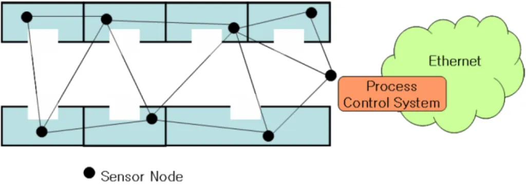
WSN(Wireless Sensor Network) is an essential technology for USN(Ubiquitous Sensor Network) and it consists of process treating collected information, transmitting and receiving devices and sink nodes. The Sink node roles sending the collected data by sensors.
WSN is not designed for communication means, but for automated remote data collecting. And it can be utilized at scientific, military and commercial application.
There are many technologies such as Z-Wave, Zigbee, Bluetooth, UWB(Ultra-Wideband), NFC(Near Field Communication) for USN.
Recently, Zigbee has been in the spotlight among low-power and low-rate technologies. Z-wave technology is similar to Zigbee technology. Z-Wave, a proprietary technology developed by Zensys of Denmark, is competing with Zigbee to become the standard for automated home controls. About 50 companies in USA or Europe adopt Z-wave technology and they are making several products.
Comparing with other technologies, Z-Wave has an advantage of low power consumption, two-way RF communication and mesh network. Its merits are available to control a sensor and device. Z-wave is possible to make it lighter, more energy efficient. With this special features, Z-Wave is expected to be a available solution in USN area.
In this thesis, the platform of automated home sensor network with Z-Wave is studied and implemented. The Z-Wave chipset, the ZW0201, is used at each sensor board. The 8-bit microcontroller interrelated 8051 is adopted to synchronize and control a sensor node. The 8051 functions at 16MHz includes 2kbyte RAM memory and 32kbyte flash ROM memory.
Using the microprocessor, it receives or transmits digital data.
Master sensor board is connected with a computer and RS-232c through UGI(User Graphic Interface).
SHT11 developed by SENSIRION is used for humidity and temperature sensor. The Z-Wave chipset, the ZW0201, and GUI is controled by C language. The compiler offered by developers kit of Zensys is used for implementing this system.
Realized sensor nodes are activated for the line of sight range 13m at hight 0m, 35m at hight 0.75m and 65m at hight 2m.
Output power is -3.619dBm at center frequency 868.42MHz. The
system is stably operated over input power 3.3V and its current
consumption is 6.8mA at standby mode, 30.3mA at active mode.
Abbreviations
USN : Ubiquitous Sensor Network WSN : Wireless Sensor Network UWB : Ultra-Wideband
NFC : Near Field Communication GUI : Graphic User Interface
MEMS : Micro Electro Mechanical System MCU : Micro Controller Unit
API : Application Program Interface OSWA : Open Sensor Web Architecture NRZ : Non Return Zero
FSK : Frequency Shift Keying
CSMA : Carrier Sense Multiple Access MPU : Micro Processor Unit
PCB : Printed Circuit Board MAC : Media Access Control PCB : Personal Digital Assistant OS : Operating System
SQL : Structured Query Language SQL : Structured Query Language QoS : Quality of Service
TTA : Telecommunication Technology Association
1
1.1
,
.
, ,
. ,
, u-City . u-City USN
, , , , , ,
,
, , ,
. ,
,
, USN USN
USN .
USN (Wireless
Sensor Network)
, (Sensor Node)
(Sink Node) .
, , ,
. WSN
Z-Wave, Zigbee, Bluethooth, UWB, NFC .
2.4GHz ISN , Zigbee
. Zigbee ,
Zensys Z-Wave Z-Wave
/ .
Z-Wave Zigbee , ,
RF, Mesh .
Z-Wave USN 9.6/40Kbps
/ , on/off, ,
, .
1.2
Z-Wave . Z-wave Chip
, /
ID .
, , , , ,
,
, , ,
.
Z-Wave , MAC
, ,
. Z-Wave
Zensys 868.42MHz ZW0201
ZW0201 8051 8bit
Microcontroller . 8051 16MHz 2kbyte
32kbyte .
,
UGI(User Graphic Interface) RS-232c
. SENSIRION
SHT11 . Z-Wave ZW0201
GUI C , Zensys Developers Kit
. Z-Wave
Controller Digital
Oscilloscope , OUTPUT POWER Agilent Spectrum
Analyzer ,
0m, 0.75m, 2m .
2 USN
2.1 USN
2.1.1 USN
USN(Ubiquitous Sensor Network) , , ,
(bade-station sink)
.
,
.
. , ,
,
.
2.1 .
2.1 USN
Fig. 2.1 USN Applications.
2.1.2 USN
USN
Ad-Hoc .
, , PDA
.
. Ad-Hoc
(AP)
.
.
.
AP
.
.
.
. 2.2 Ad-Hoc
.
2.2 Ad-Hoc
Fig. 2.2 Structure of ensor network using Ad-Hoc.
.
. 8bit CPU 8kByte ,
128Kbyte
, .
micro-controller .
(actuator)
.
.
.
.
. (
) ( )
1 (hop)
, (Sink
Node) .
,
.
USN , , , ,
.
,
, , ,
, ,
.
CPU , ,
, ,
, .
WSN
, , ,
,
.
,
, / ,
, /
.
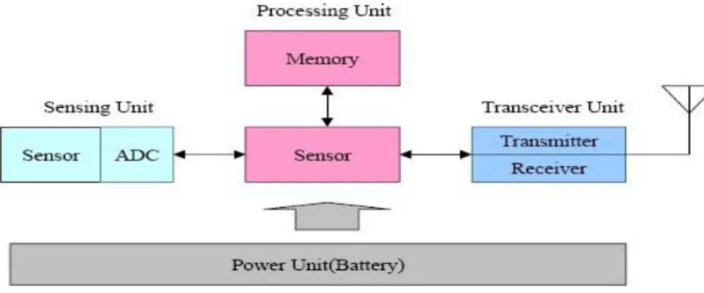
2.3
Fig. 2.3 The component structure of sensor node.
, ,
. USN , , USN
.
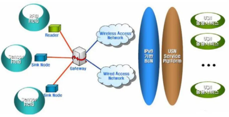
USN 2.4 . Access
Network IPv6 BcN USN
IPv6 .
.
2.4 USN
Fig. 2.4 Schematic diagram of USN.
2.2 USN
2.2.1 USN
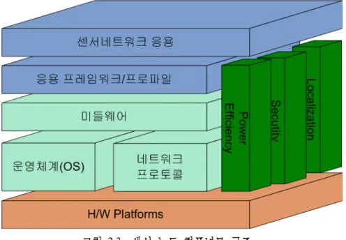
USN 2.1
, (OS), , USN
. .
,
. , ,
.
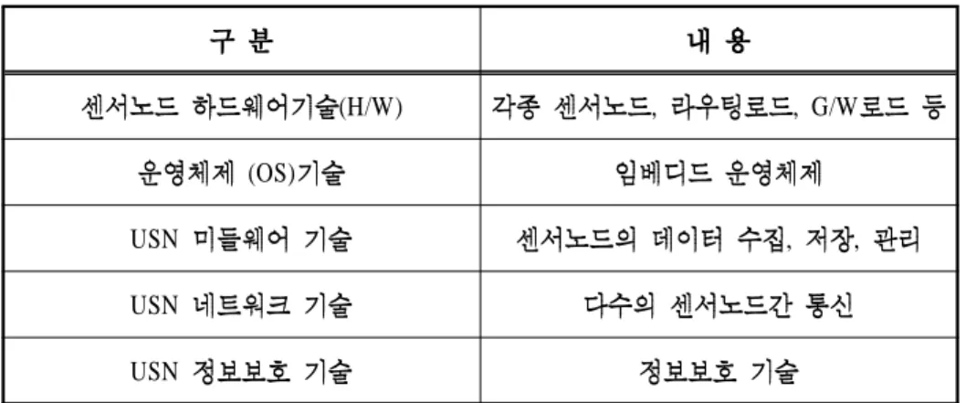
(H/W) , , G/W (OS)
USN , ,
USN USN 2.1 USN
Table 2.1 Core technology of USN.
.
.
.
2.5 , ,
. MEMS(Micro Electro Mechanical System)
Bio .
MCU(Micro Controller Unit) Atmel
Atmega128L, TI MSP430, PIC18F
IEEE 1451 .
2.5
Fig. 2.5 Structure of sensor node.
.
Atmel, ARM, Motorola ,
.
USN OS
OS
. OS ,
, , I/O, ,
, API .
OS 32~128Kbyte , OS
4~8Kbyte OS
. OS
UC Tiny OS, UCLA SOS,
MANTIS, TRON
T-Engine . ANTS, ETRI
Nano-Qplus OS .
, , . USN
USN ,
, , ,
, 2.2
( ) USN
(USN ) .
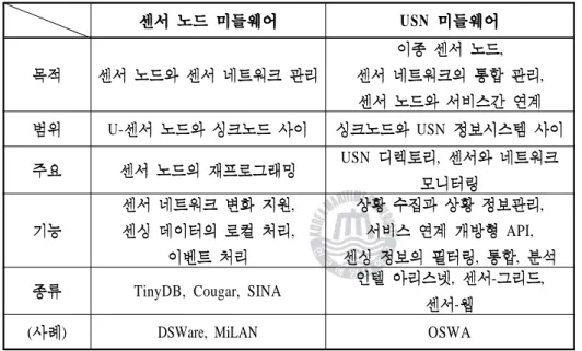
USN
, ,
U- USN
USN ,
, ,
, API, , ,
TinyDB, Cougar, SINA , - ,
-
( ) DSWare, MiLAN OSWA
2.2 USN
Table 2.2 Compare middleware of sensor node with middleware of USN.
, , , ,
, ,
( ) . TinyDB, TinySec,
Cougar, SINA, DSWare, MiLAN . USN , ,
, , , , USN
, .
USN USN , U- , USN
, USN API
.
, , - (Sensor-Grid), -
(Sensor-Web), OSWA(Open Sensor Web Architecture) USN
R&D . 2.3 USN
.
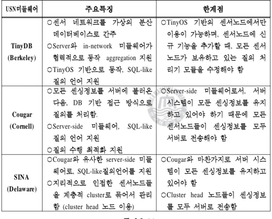
2.3 USN
Table 2.3 Features of USN middleware and a limit.
USN
TinyDB (Berkeley)
Server in-network
aggregation
TinyOS , SQL-like
TinyOS
,
,
Cougar (Cornell)
, DB
.
Server-side , SQL-like
Server-side ,
SINA (Delaware)
Cougar server-side , SQL-like
cluster
(cluster head )
Cougar
Cluster head
2.3 (a)
USN
Impala (Princeton)
Binary
Hewlett-Packard
,
DSWare (Virginia)
DB SQL-like
in-network aggregation
,
Milan (Rochester)
USN QoS
QoS
lifetime QoS
USN tightly-coupled
Mate (Berkeley)
(TinyOS )
Byte code Virtual Machine(VM)
VM
,
interpretation
COSMOS (ETRI)
( , , )
In-network aggregation
2.3 (b)
,
.
, .
,
. 2.6 .
2.6
Fig. 2.6 Specification of sensor network protocol.
.
. .
.
, .
MAC .
, Z-Wave,
, HomeRF, ZigBee, , 1394
1394, UWB Z-Wave
. 2.4 .
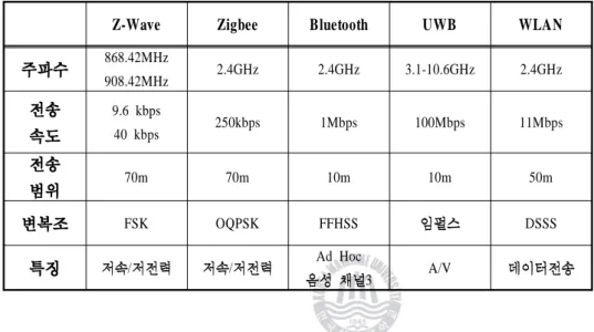
2.4
Table 2.4 Wireless communication technologies.
Z-Wave Zigbee Bluetooth UWB WLAN
868.42MHz
908.42MHz 2.4GHz 2.4GHz 3.1-10.6GHz 2.4GHz 9.6 kbps
40 kbps 250kbps 1Mbps 100Mbps 11Mbps
70m 70m 10m 10m 50m
FSK OQPSK FFHSS DSSS
/ / Ad Hoc
3 A/V
2.2.2 USN
,
. 1993 NIST IEEE IEEE1451
. IEEE 802.15 ,
ZigBee Aliance, IETF 6LoWPAN , IPv6 Convergence
.
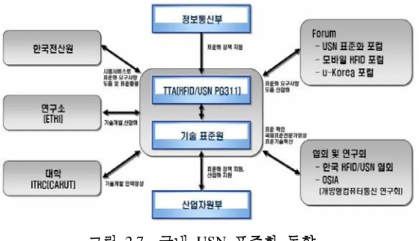
TTA RFID/USN 2004 USN
, , ,
. 2.7
.
2.7 USN
Fig. 2.7 standardization movement of domestic USN.
IPv6 Convergnce .
IPv6 IPv6
IPv6
. IT IT839
IT .
IPv6 USN .
3 Z-Wave
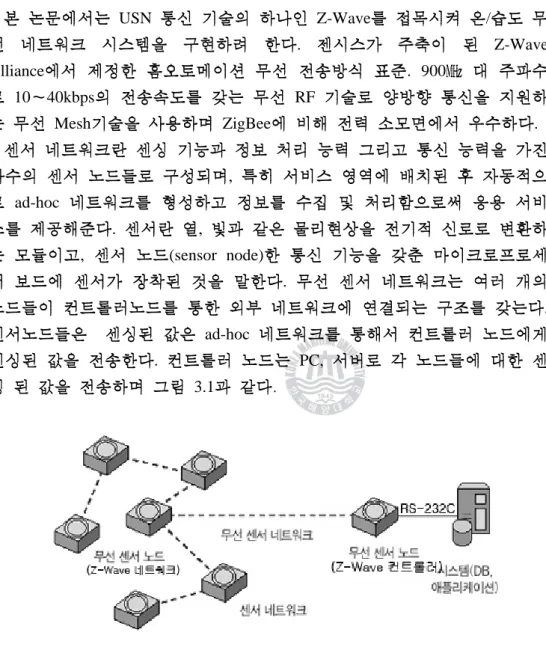
3.1 Z-Wave
USN Z-Wave /
. Z-Wave
Alliance . 900
10 40kbps RF
Mesh ZigBee .
, ad-hoc
. ,
, (sensor node) .
. ad-hoc
. PC,
3.1 .
3.1 Z-Wave
Fig. 3.1 Schematic diagram of Z-Wave sensor network.
3.1 Z-Wave Zigbee
Table 3.1 Features of Z-Wave and Zigbee.
Z-Wave(ZW0201) Zigbee(CC2420)
RF Transceiver
Frequency 868.42MHz(EU)/
908.42MHz(US)
868.42MHz(EU)/
908.42MHz(US) 2,4GH/z(Globa)l Data rate 9.6 kbps/ 40 kbps
20 kbps /40 kbps /250 kbps High
sensitivity
9.6 kbit : -104 dBm
40 kbit : -101 dBm 250 kbps : -94 dBm
Modulation FSK O-QPSK
Coding Manchester Coding No Use
Spreading/PSK Microcontroller
Core 8051 MCU 8051 MCU
Clock
Frequency 16MHz 16MHz
Memory Flach Memory 32 kbyte 32 kbyte
SRAM 2 kbyte 2 kbyte
3.2 Z-Wave (Z-Wave )
3.2 Z-Wave
Fig. 3.2 The layer structure of Z-Wave.
3.2.1 (Physical Layer)
RF MEDIA , Manchester
NRZ , FSK .
3.2.2 (Mac Layer)
Z-Wave Mac layer RF Manchester
, (SOF), (EOF)
.
3.3 MAC FRAME
Fig. 3.3 The transmission structure of MAC layer's FRAME.
little endian , ,
Mac layer
access Manchester
.
8 ,
DC free Manchester .
(Collision avoidance) .
3.4 Manchester Fig. 3.4 Manchester code.
/
. CSMA
.
3.5 Backoff
Fig. 3.5 backoff algorithm.
CSMA
free busy .
CSMA
.
A
B C
CSMA B C A
free
.
.
3.2.3 (Transfer Layer)
Z-Wave ,
.
. Frame Layout
Z-Wave 4
. - Singlecast Frame Type
- Transfer Acknowledge Frame Type - Multicast Frame Type
- Broadcast Frame Type
Z-Wave 3.6
.
7 6 5 4 3 2 1 0 Home ID
Source Node ID Frame Header
Length Destination Address
Data Byte 0 Data Byte 1 Data Byte 2
...
Data Byte n Checksum 3.6 Z-Wave
Fig. 3.6 The frame structure of Z-Wave.
. Single cast Frame Type
,
. .
.
3.7
Fig. 3.7 The frame structure of singlecast.
. Transfer Acknowledge Frame Type
. 3.7
.
. Multicast Frame Type
1~232 .
.
3.8 Multicast Frame Fig. 3.8 Multicast frame transmission.
, .
.
.
. Broadcast Frame Type
. .
.
.
3.9
Fig. 3.9 Retransmit of transmission layer.
3.10 Broadcast Frame Fig. 3.10 Broadcast frame transmission.
3.9 .
3.9 . B
Ack
Ack A B A
. 3.9
.
3.2.4 (Routing Layer)
Z-Wave
.
. ,
.
.
. Frame Layout
Z-Wave 2
. Routed Single cast Frame Type Z-Wave 3.11
. ,
.
3.11 Routed Single cast Frame Fig. 3.11 Routed single cast frame transmission.
. Routed Acknowledge Frame Type
Z-Wave
. .
3.12 Routed Acknowledge Frame Fig. 3.12 Routed acknowledge frame transmission.
. Routing Table
.
.
, .
3.13
Fig. 3.13 Routing table of network topology.
. Route to Node
. .
,
.
3.2.5 (Application Layer)
Z-Wave Z-Wave
.
. Frame Layout
Z-Wave 3.14
.
7 6 5 4 3 2 1 0
Single/Multi/Broadcast frame header Application command class
Application command Command parameter 1 Command parameter 2
...
Command parameter n
3.14 Z-Wave
Fig. 3.14 Routing table of network topology.
4 Z-Wave
4.1 Z-Wave , ,
EEPROM, RS-232, , , PIC
.
4.1 Z-Wave
Fig. 4.1 Z-Wave Board block diagram.
Z-Wave Chip Z-Wave RF .
4.1 Z-Wave Chip ,
4.1 / Z-Wave RF
RS-232
PC . Z-Wave
EEPROM
ID ID
.
4.2 Z-Wave Chip Z-Wave
Fig. 4.2 Communication module designed by Z-Wave Chip.
4.3
Fig. 4.3 Temperature-Humidity sensor node design.
Temperature & Humidity Sensor SHT11 14 AD . Calibration memory
Calibration .
. 2-wire MPU
, 2.7V 5.5V 280uA
, 0.1uA . -40
+80 2 , -40 +100
.
4.1 /
Table 4.1 Temperature & Humidity Sensor spec.
Sensor Sensirion SHT11
Channel Humidity Temperature
Range 0 ~100 % -40 ~ 80 °C
Accuracy ± 3 % RH(Typical) ± 0.5 °C
Operation Volt 2.4 ~ 5.5V
(a) (b)
4.4 (a) ; (b) MAIN PCB
Fig. 4.4 Layout (a) Sensor module ; (b) Main PCB.
(a) (b)
4.5 (a) Z-Wave ; (b) MAIN PCB
Fig. 4.5 (a) Z-Wave sensor module. ; (b) Main sensor module PCB.
4.4 PCB . 4.4 (a) Z-Wave
PCB 4.4 (b) MAIN PCB .
4.26 (a) ZW0201 4.5 (b)
. , Transmission line 4.5 (b)
MAIN PCB .
4.2
4.2.1
4.6
Fig. 4.6 Flowchart of controller node.
4.6 Z-Wave .
H/W S/W Init Z-Wave Sleep mode
. Z-Wave wake-up .
,
Ack Sleep mode cycle
.
4.2.2
4.7 H/W Init, S/W Init,
Application Poll, Application Command
Handler .
H/W Init , S/W Init
. Application Poll Application
Command Handler Application Poll
, Application Command Handler
.
.
4.7
Fig. 4.7 Flowchart of sensor module.
.
4.2
Table 4.2 Hardware initialize function.
BYTE ApplicationInitHW(BYTE bWakeupReason) {
PIN_IN(Button, 1); //
PIN_OUT(SSN); //SCK PIN_OUT(MISO); //DATA return(TRUE);
}
4.3
Table 4.3 software initialize function.
BYTE ApplicationInitSW( void ) {
LoadConfiguration(); //EEPROM AssociationInit(); //
OneButtonInit(); //
return(TRUE);
}
4.4 ApplicationCommandHandler
Table 4.4 ApplicationCommandHandler function acquired data.
long data1, data2;
char humi_tempo1, humi_tempo2, temp_tempo1, temp_tempo2;
post02_Read(MEASURE_HUMI, &data1, &data2); //
humd_data1 = data1;
humd_data2 = data2;
post02_Read_temp(MEASURE_TEMP, &data1, &data2); //
temp_data1 = data1;
temp_data2 = data2;
txBuf.ZW_SensorMultilevelReport4byteFrame.cmdClass = COMMAND_CLASS_SENSOR_MULTILEVEL;
txBuf.ZW_SensorMultilevelReport4byteFrame.cmd
= SENSOR_MULTILEVEL_REPORT;
txBuf.ZW_SensorMultilevelReport4byteFrame.sensorType = 0x01;
txBuf.ZW_SensorMultilevelReport4byteFrame.precisionScaleSize = 0x44;
txBuf.ZW_SensorMultilevelReport4byteFrame.sensorValue1 = humd_data1;
txBuf.ZW_SensorMultilevelReport4byteFrame.sensorValue2 = humd_data2;
txBuf.ZW_SensorMultilevelReport4byteFrame.sensorValue3 = temp_data1;
txBuf.ZW_SensorMultilevelReport4byteFrame.sensorValue4 = temp_data2;
// , 2Byte
7 6 5 4 3 2 1 0 Command Class = COMMAND_CLASS_SENSOR_MULTILEVEL(0x31)
Command = SENSOR_MULTILEVEL_REPORT(0x05) Sensor Type
Precision Scale Size
Sensor Value 1 Sensor Value 2
Sensor Value n
4.8 /
Fig. 4.8 Packet of temperature-humidity sensor data structure.
01 : Start Of Frame
0E : (SOF Checksum )
00 : Request
04 : FUNC_ID_APPLICATION_COMMAND_HANDER 00 : bStatus
02 : 08 :
31 : COMMAND_CLASS_SENSOR_MULTILEVEL 05 : SENSOR_MULTILEVEL_REPORT
01 :
44 : ( )
06 : Byte
7C : Byte
18 : Byte
CA : Byte
26 : Checksum
4.3 Z-Wave
. ( , , , ,
)
(a)
(b) (c)
(d) (e)
4.9 /
Fig. 4.9 Temperature-humidity sensor data waveform.
4.9 Z-Wave
. Clock 15ms 3.3V .
14bit , 12bit .
SHT11
. 4.9
. 4.9 (a), (b), (d) Z-Wave , 4.30 (c), (d)
Z-Wave .
.
4.10 Z-Wave
Fig. 4.10 A structure of Z-Wave system.
4.11
Fig. 4.11 Measure the communication distance.
4.10 Z-Wave . Main
RS-232 ,
. 3.6V .
.4.11 .
0m, 0.75m, 2m . 5m
1m .
0m 13m 0.75m 35m 2m
65m . 3.10 .
4.5 (a) 0m ; (b) 0.75m ; (c) 2m
Table 4.5 Measure the communication distance is followed by height. (a) height 0m ; (b) height 0.75m ; (c) height 2m
(a)
5m 0m 50 0
10m 0m 50 0
11m 0m 50 0
12m 0m 50 0
13m 0m 50 2
14m 0m 50 7
15m 0m 50 11
(b)
10m 0.75m 50 0
15m 0.75m 50 0
20m 0.75m 50 0
25m 0.75m 50 0
30m 0.75m 50 0
31m 0.75m 50 0
32m 0.75m 50 0
33m 0.75m 50 3
34m 0.75m 50 3
35m 0.75m 50 13
(c)
10m 2m 50 0
20m 2m 50 0
30m 2m 50 0
40m 2m 50 0
50m 2m 50 0
60m 2m 50 0
65m 2m 50 0
70m 2m 50 13
75m 2m 50 39
(a) (b)
4.12 (a) ; (b)
Fig. 4.12 Measure the consumption current (a) standby mode ; (b) active mode.
.4.12 .
. 6.8mA, 30.3mA
.
(a)
(b)
(c)
4.13 Z-Wave (a) 868.42MHz ; (b)
867.6MHz ; (c) 869.2MHz
Fig. 4.13 The output frequency measurement of Z-Wave sensor node (a) Center frequency 868.42MHz ; (b) Guard frequency 868.42MHz ; (c) Guard frequency 869.2MHz.
4.14 PC application
Fig. 4.14 Output of PC application programing.
4.15 30
4.15 TXT
Fig. 4.15 Saved data of TXT output.
5
USN , ,
,
. , IT
,
USN . USN
. Z-Wave Zigbee
, , RF, Mesh
. Z-Wave USN
9.6/40Kbps / , on/off, ,
, .
Z-Wave
. Z-Wave Zensys
868.42MHz ZW0201
ZW0201 8051 8bit Microcontroller
. 8051 16MHz 2kbyte 32kbyte
.
, GUI(Graphic User Interface)
RS-232c .
SENSIRION SHT11 .
Z-Wave ZW0201 GUI C ,
Zensys Developers Kit
0m 13m 0.75m
35m 2m 65m .
868.42MHz Output power -3.619dBm 3.3V
6.8mA,
30.3mA .
.
[1] “IT389 ”, ,2004.10
[2] , “WSN ”, 2008. 10.
[3] “IT ”, ,2006. 2.
[4] “A survey on Sensor Networks", Ian F. Akyildiz, Weilian Su, Yogesh Sankarasubramaniam, and Erdal Cayirci Georgia Institute of Technology, IEEE Communications Magazine, August, 2002
[5] http://www.zen-sys.com/modules/Zensys/
[6] http://www.z-wave.com/
[7] ,“ ”, TTA , 95 ,
, P.7
[8] , “
”, , 2002. 11.
[9] , “ ”, 2002. 10.
[10] , “ ”, TTA, IT
Standard Weekly 2004-16 , 2003. 4.
[11] , “u- ”, 2004. 2.
[12] , “Digital Life Digital Home ”,
2003. 5.
[13] Yoshihiro KAWAKARA, Massateru MINAMI, Hiroyuki Morikawa, and tomonori AOYAMA, “Design and Implementation of Sensor Network Node for Ubiquitous Computing Environment”, In Proceedings of IEEE Semiannual Vehicular Technology Conference, Orland, USA, October 2003
[14] , , “ ”, , 2006
[15] , “USN ”,
22 3 , 2007.6
2
.
.
.
.
.
, ,
, .
, ,
, ,
,
, , ,
, ,
, , ,
, , .
,
, ,
.
, .
.