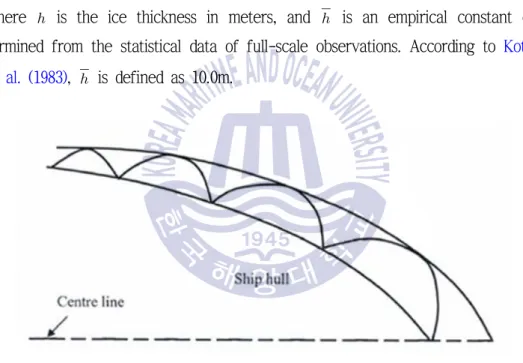
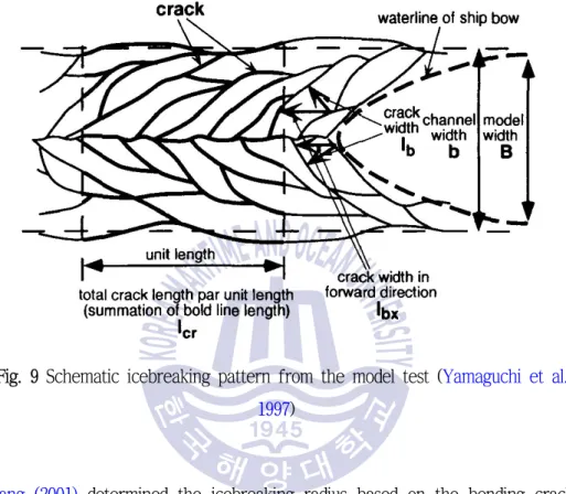
얼음 파괴 패턴과 얼음 선체 접촉 조건을 고려한 얼음 저항 추정 기법에 대한 조사. 본 연구에서는 얼음-선체 상호작용 현상의 조사와 함께 쇄빙 패턴은 다음과 같다. 또한, 빙수선박의 모형시험 및 해석에 대해 많은 조언을 해주신 현대중공업 선박성능연구부 박경덕 실장님께도 진심으로 감사의 말씀을 드립니다.
Introduction
Objectives
In the present study, the author clarifies the contact conditions of ice hulls and ice breaking patterns during the interaction process of ice hulls. In particular, new semi-empirical icebreaker patterns are derived from the model test results in the ice tank of the Korea Research Institute of Ships and Ocean Engineering (KRISO), and the pressure area effect is taken into account. In addition, the developed numerical model allows us to predict the ice resistance at the design stage of ice ships with different ice conditions and hull shapes.
Approaches and Methodology
Organization of Thesis
Reviews on Ice Resistance Prediction
Empirical and Analytical Approaches
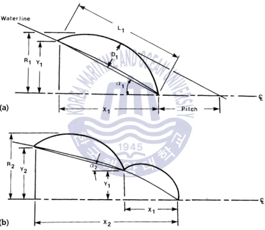
The wedged arch shape was considered and the ice resistance was divided into three categories crushing, breaking and immersion. Lindqvist's model assumed that the ice resistance increased linearly with the ship's speed and the empirical constants in the velocity term were used to calculate the total ice resistance. 1997) investigated the prediction of ice resistance. In particular, the ice breaking component of the total ice resistance can be obtained by subtracting the resistance in pre-sawn ice from the total ice resistance.
Numerical Approaches
When calculating ice resistance, they took into account rudder and propeller force, hydrodynamic force and ice force. The icebreaking force was calculated based on the numerical results in the FE-fluid-structural interaction and ship maneuvering with the. A comparison of the results of the numerical simulations and the ice tank tests was performed to validate the developed model. 2013) introduced a numerical model to simulate ice-hull interaction.
Development of Ice Resistance Prediction Model
Ship Resistance in Ice
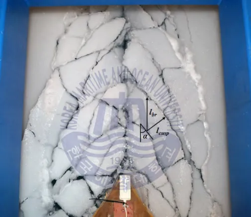
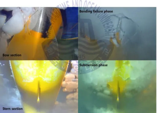
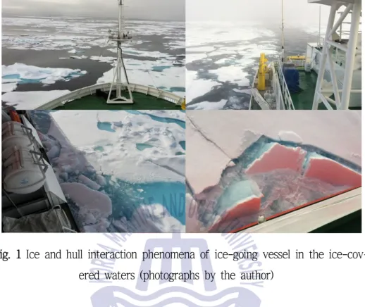
1 Phenomena of the interaction of ice and the hull of a vessel on ice in ice-covered waters (photos by the author). The fracture length was calculated depending on the thickness of the ice and the modulus of elasticity of the ice. Calculation of the ice-hull contact area is an important aspect of this study.
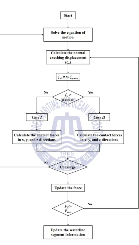
Calculation of Ship Resistance in Ice
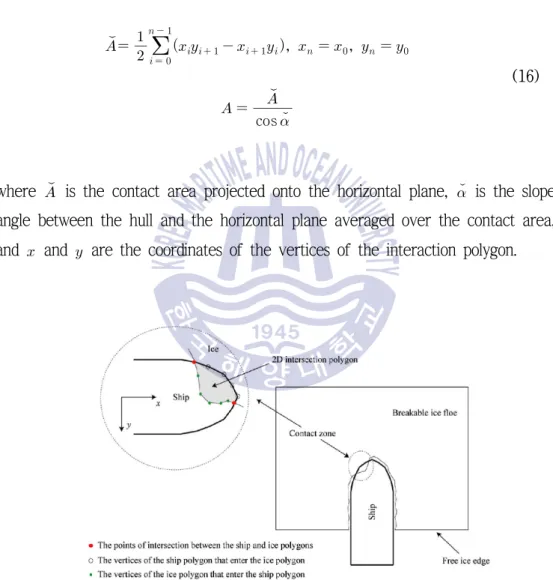
The normal contact force, , can be calculated as where is the uniaxial crushing strength of ice and is the normal contact area. The values for and were determined from the large-scale ice test of the Korean icebreaker Araon in the Beaufort Sea. In particular, kinetic energy is related to the effective mass and normal speed of the ship.
The indentation energy is the integral of the normal contact force on the normal crushing displacement. The frictional force acts on the horizontal plane at the waterline level in the direction tangent to the waterline; therefore, only components in the and directions can be considered. The vertical component, , and the horizontal component, , are related to the ice sheet failure criterion and the ship's resistance in ice.
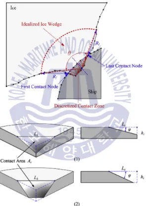
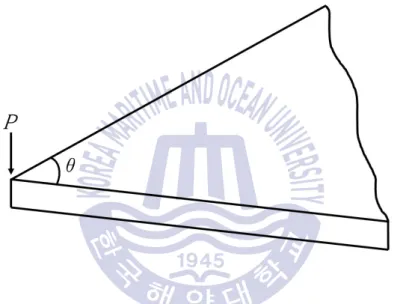
To define the failure mode of the ice floe in the current model, the failure criterion must be determined. Kerr (1975) also generalized formulas for the failure load, , of a floating ice wedge plate with an opening angle, , and the relationship is expressed as (see ... where is an empirical parameter. 2010) studied the effect of the empirical parameter. The determination of the maximum load, m ax, at which ice collapses is determined on the basis of the criterion.
In the calculation, if the maximum concentrated load m ax is greater than , the failure mode of the ice sheet mainly consists of crushing and shearing phases, but when exceeds m ax enough, buckling failure occurs. appear.
Motion Analysis by Numerical Integration
In this study, a numerical integration method called the Newmark- method is used to analyze the ship motion and ice resistance characteristics. The Newmark- method is based on the assumption that acceleration varied linearly between two time instants. The coefficients and indicate how much acceleration enters the velocity and displacement equations at the end of the interval.
Equation (36) can be used to find a solution for displacements, velocities and accelerations at time. The iteration is continued until the change in excitation from one interaction to the next is small enough.
Comparison of Ice Resistance between Predictions
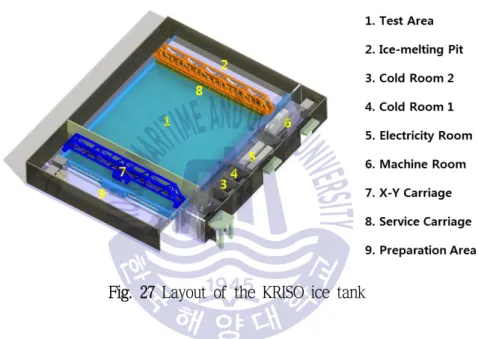
Experimental Test in Ice Tank
A service van is installed for model production and processing of the ice in the model test. Model properties are routinely measured for each ice sheet, and a database of model properties is maintained for quality control and prediction. The measurement of the flexural strength of the model is carried out for each test channel before the test.
The elastic modulus of model ice is determined by the ice sheet plate deflection method. The coefficient of friction between the surface of the model hull and the ice is determined using the friction test. The model ice was prepared based on the standard procedure of the KRISO ice tank (KRISO, 2015).
In the tests, the surface of the model hull was painted with a special painting technique to achieve the necessary coefficient of friction between the surface of the model hull and the ice. To evaluate the performance of the ship models, the series of model tests listed below were carried out:. Speed of the ship model: The ship model is towed in by the main carriage.
It is assumed that the speed of the ship model is equal to the main speed of the X-car.
Discussions
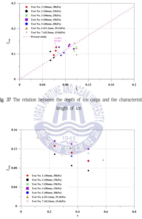
In this study, the main features of the Arctic LNGC model and model test results were excluded. The relationship between the depth of ice cusps and the ratio between the characteristic length of the ice and the ship speed is shown in Figure 39. The relationship between the depth of ice cusps and the ratio between the characteristic length of the ice and the ship speed.
The characteristics of these components for the number of ice points are considered for the Korean icebreaker model. 40 The relationship between the size of crushing and breaking components and the number of ice tips for the Korean icebreaker model. The number of ice peaks for the parameters (namely and ) in the pressure range effect is summarized in Table 4.
Figures 46 and 47 show the model test results in flat ice and pre-cut ice conditions. 45 The ice resistance characteristics of the Korean icebreaker model for different ice thicknesses and strengths. The comparisons of model test results and calculated results derived from Lindqvist's model and the current model are shown in Fig.
57 Comparison of model test results and calculated results using the Lindqvist model for the Korean icebreaker model. 58 Comparison of model test results and calculated results using the current model for the Korean icebreaker model. 59 Comparison of model test results and calculated results using the Lindqvist model and the current model for the Arctic PSV model.
Conclusions and Recommendations
Conclusions
As a result, the depth of the ice points has a decreasing trend in the higher speed regions. In the wide beam and sharp arch shape, the breaking resistance is lower than expected. However, there are no significant relationships between the parameters in the pressure area effect and the number of ice points.
Regarding the failure of the wedge plate, the empirical parameter must be determined. The empirical parameter can be particularly influenced by the strength number and the Froude number, because the empirical parameter is related to the strength of the ice. In the simulation, ice hull contact conditions mainly involve triangular crushing, while quadrilateral crushing rarely occurs.
When the ice is thick, the contact area increases during the ice-hull interaction, and the ice pressure decreases dramatically. Based on the h-v curve, the Korean icebreaker, Araon practically meets the performance requirements in the design condition. Finally, defining the icebreaker pattern and parameters used in the current study will be useful for future studies of ship performance in ice.
In addition, the developed numerical model can contribute to the tests in the KRISO ice tank by helping to predict the ice resistance of ships, given different ice conditions and hull shapes.
Recommendations
Proceedings of the 15th International Conference on Port and Ocean Engineering under Arctic Conditions (POAC), Vol. A review of experimental indications of the relationship between immersion and breakage of flat ice components. Proceedings of the 7th International Conference on Port and Ocean Engineering under Arctic Conditions (POAC), pp.
Proceedings of the 22nd International Conference on Port and Ocean Engineering under Arctic Conditions (POAC), POAC13_075. Proceedings of the 11th International Conference and Exhibition on Performance of Ships and Structures in Ice (ICETECH),. Proceedings of 10th International Conference on Port and Ocean Engineering under Arctic Conditions (POAC), Lulea,.
Proceedings of the 11th International Conference on Port and Ocean Engineering under Arctic Conditions (POAC). Mathematical modeling interaction modeling for real-time simulations of ship maneuvering in level ice. Proceedings of the 5th International Conference on Port and Ocean Engineering Under Arctic Conditions (POAC).
On the mechanics of ice loading of ships in smooth ice in the Baltic Sea.