저작자표시-비영리-변경금지 2.0 대한민국 이용자는 아래의 조건을 따르는 경우에 한하여 자유롭게
l 이 저작물을 복제, 배포, 전송, 전시, 공연 및 방송할 수 있습니다. 다음과 같은 조건을 따라야 합니다:
l 귀하는, 이 저작물의 재이용이나 배포의 경우, 이 저작물에 적용된 이용허락조건 을 명확하게 나타내어야 합니다.
l 저작권자로부터 별도의 허가를 받으면 이러한 조건들은 적용되지 않습니다.
저작권법에 따른 이용자의 권리는 위의 내용에 의하여 영향을 받지 않습니다. 이것은 이용허락규약(Legal Code)을 이해하기 쉽게 요약한 것입니다.
Disclaimer
저작자표시. 귀하는 원저작자를 표시하여야 합니다.
비영리. 귀하는 이 저작물을 영리 목적으로 이용할 수 없습니다.
변경금지. 귀하는 이 저작물을 개작, 변형 또는 가공할 수 없습니다.
Doctoral Dissertation
Failure Mechanism of Lithium–Oxygen Batteries with a Redox Mediator
Seongmin Ha
Department of Energy Engineering (Battery Science and Technology)
Graduate School of UNIST
2018
Failure Mechanism of Lithium–Oxygen Batteries with a Redox Mediator
Seongmin Ha
Department of Energy Engineering (Battery Science and Technology)
Graduate School of UNIST
Abstract
Lithium–oxygen (Li–O2) batteries are receiving large attention as a promising energy storage system for electrically powered mobile devices from mobile phone to electric vehicles due to their high energy density. However, the practical utilization of Li–O2 batteries remain insufficient due to several drawbacks such as poor energy efficiency and cycle performance. Solid catalysts are suggested for reduced polarization of Li–O2 batteries, resulting in the improving energy efficiency. However, solid catalysts exhibit the limited performance of Li–O2 batteries due to the spatial limitation. The redox mediators as soluble catalysts has been introduced for not only improving energy efficiency, but also surmounting spatial constraint of solid catalysts for Li–O2 batteries. The redox mediators effectively decreases the polarization for oxygen evolution reactions (OER) in the Li–O2 batteries, leading to improving electrochemical performance. On the other hand, the reduced polarization by redox mediators gradually reverts to original high polarization over a certain number of cycles owing to a continuous loss of their catalytic activity as cycle number increasing. The shuttle effect for redox mediators has been considered to be associated with the degradation of Li–O2 batteries with redox mediators, however, the failure mechanism does not fully elucidate the increasing polarization and loss of capacity observed with Li–O2 batteries.
In this dissertation, it is demonstrated that the Li–O2 cells involved redox mediator deteriorates due to low compatibility between redox mediator and cell components, such as electrolyte solvent and Li metal anode. The electrolyte solvents influence on the electrochemical reversibility and radical stability of redox mediator. It is demonstrated that the radical stability of redox mediator dominantly influence on the cycle performance of Li–O2 batteries with redox mediator, whereas the electrochemical reversibility of redox mediator is hardly related with that of Li–O2 batteries. Therefore, the appropriate solvent for the redox mediator promotes the stability of redox mediator radical, resulting in the enhanced performance of Li–O2 batteries. Furthermore, the side reaction of redox mediator aggravates the electrochemical performance of Li metal and exhausts the redox mediators simultaneously. This unexpected reaction arises even though protective layer on the Li surface, which consists of lithium oxides formed by the oxygen contained in the electrolytes, covers the surface of Li metal. However, the introducing of LiNO3 as a salt, which can act two roles, such as the fast protective layer generator and a capturer for the redox mediator radicals, alleviates the side reaction, resulting in the improved cycle performance of Li–O2 batteries. Therefore, the optimization of electrolyte and the protection of Li metal anode for redox mediator strongly influence on the improving performance of Li–O2 batteries with a redox mediator. To clarify the failure mechanism of Li–O2 batteries containing redox mediators, 10–
Keywords: Lithium oxygen batteries, Failure mechanism, Redox mediator, Electrolyte, Lithium metal anode
Contents
Abstract --- i
List of Figures --- vi
List of Tables --- xi
Abbreviations --- xii
1. Introduction --- 1
1.1 Next–generation rechargeable batteries --- 1
1.1.1 Post lithium–ion batteries (PLIBs) --- 3
1.1.2 Sulfur–based batteries (Li–S batteries) --- 15
1.2 Lithium–Oxygen batteries (Li–O2 batteries) --- 18
1.3 Research motivation --- 25
1.4 Characterization --- 26
2. 10–methlyphenothiazine (MPT) as a redox mediator for facilitating oxygen evolution reaction of Li–O2 batteries --- 29
2.1 Introduction --- 29
2.2 Experimental details --- 33
2.2.1 Materials --- 33
2.2.2 Electrode preparation --- 33
2.2.3 Electrochemical characterization --- 33
2.2.4. Characterization --- 34
2.3 Result and Discussion --- 35
2.4 Summary --- 42
3. The appropriate electrolyte solvent for redox mediator in the Li–O2 batteries --- 43
3.1 Introduction --- 43
3.2 Experimental details --- 45
3.2.1 Materials --- 45
3.2.2 Electrode preparation --- 45
3.2.3 Electrochemical characterization --- 45
3.2.4 Characterization --- 46
3.3 Result and Discussion --- 47
3.4 Summary --- 55
4. The stability of redox mediator with lithium metal anode for Li–O2 batteries --- 57
4.1 Introduction --- 57
4.2 Experimental details --- 58
4.2.1 Materials --- 58
4.2.2 Electrode preparation --- 58
4.2.3 Electrochemical characterization --- 58
4.2.4 Characterization --- 59
4.3 Result and Discussion --- 61
4.3.1 Failure mechanism of Li–O2 cells containing a redox mediator --- 61
4.3.2 Redox mediator protection --- 71
4.4 Summary --- 78
5. Conclusion --- 79
References --- 80
List of Figures
Figure 1.1 (a) The present value and target value (for 500 km per charge) of specific energy for the present and future generation of battery pack, cell, electrodes, and cathode active materials. Reprinted by permission from ref. 2. Copyright 2015 Royal Society of Chemistry. (b) Improvement of the specific energy and energy density of cell level Li–ion batteries (LIBs) from 1991 to 2017. Reprinted by permission from ref. 3. Copyright 2017 Springer Nature. --- 2 Figure 1.2 (a) Phase diagram of the ternary system between LiNiO2, LiCoO2, and LiMnO2 with some representative composition. Reprinted by permission from ref. 12. Copyright 2017 The Electrochemical Society. (b) Crystal structure of layered LiMO2 (M = Ni, Co, and/or Mn). Reprinted by permission from ref. 8. Copyright 2016 Springer Nature. --- 8 Figure 1.3 (a) Proposed phase transition process from layered to spinel–like structure of TM over charging. Reprinted by permission from ref. 8. Copyright 2016 Springer Nature. (b) Partial crystal structure change of LiNi0.5Co0.2Mn0.3O2 on the surface region after 50 cycles. Reprinted by permission from ref. 15. Copyright 2013 John Wiley & Sons, Inc.. --- 9 Figure 1.4 (a) Crystal structure of over–lithiated oxide (OLO). Reprinted by permission from ref. 8.
Copyright 2016 Springer Nature. (b) Voltage profile during charge and (c) dQ/dV plot during discharge of 1st cycle for 0.35LiMn2O3·0.65Li(Ni0.35Co0.20Mn0.45)O2. Reprinted by permission from ref. 12.
Copyright 2017 The Electrochemical Society. --- 10 Figure 1.5 Schematic diagrams (a) for the failure mechanism of Si anode and (b) of nanostructured Si anodes and their composites. Reprinted by permission from ref. 8. Copyright 2016 Springer Nature. - --- 11 Figure 1.6 Schematic diagrams of (a) reaction process toward SiOx anode and (b) pre–lithiated Si anodes via a solution and electrochemical processes. Reprinted by permission from ref. 8. Copyright 2016 Springer Nature. --- 12 Figure 1.7 Schematic diagrams of (a) the failure mechanism toward Li metal during cycling. Reprinted by permission from ref. 79. Copyright 2017 Springer Nature. (b) Schematic cross–section diagram of the “mosaic” morphology of solid–electrolyte interphase (SEI) on the Li metal. --- 13 Figure 1.8 Schematic diagram of (a) the self–healing electrostatic shield (SHES) mechanism toward Li metal during cycling. Reprinted by permission from ref. 113. Copyright 2013 American Chemical Society. (b) Schematic cross–section diagram of the artificial layer for isolating and controlling the interface between Li metal and electrolyte. Reprinted by permission from ref. 8. Copyright 2016 Springer Nature. --- 14 Figure 1.9 (a) Schematic diagram of the carbon encapsulated S (yellow) electrode. Reprinted by permission from ref. 148. Copyright 2009 Springer Nature. (b) Schematic diagram for comparison of lithiation reaction in Li–S batteries (LSB) depending on Li+ desolvation. Reprinted by permission from
ref. 8. Copyright 2016 Springer Nature. (c) Synthetic process diagram for copolymerization of S8 with 1,3–diisopro–penylbenzene (DIB) to form chemically stable sulfur polymer. Reprinted by permission from ref. 156. Copyright Springer Nature. --- 17 Figure 1.10 (a) Schematic diagram of Li–O2 batteries with the reaction process during discharge/charge.
(b) Schematic diagram of the various type of Li–O2 batteries depending on the electrolyte system.
Reprinted by permission from ref. 159. Copyright 2014 American Chemical Society. (c) Typical galvanostatic voltage profile of Li–O2 batteries. --- 22 Figure 1.11 Schematic diagrams of (a) reduction mechanism in the Li–O2 batteries at low overpotential and (b) the mechanisms of surface and solution growth in the Li–O2 batteries depending on the electrolyte solvents. Reprinted by permission from ref. 162. Copyright 2016 Springer Nature. --- 23 Figure 1.12 (a) Galvanonstatic voltage profile (left) and differential electrochemical mass spectroscopy (DEMS, right) analysis of Li–O2 cell loaded Ir/rGO catalysts. Reprinted by permission from ref. 195.
Copyright 2016 Springer Nature. (b) Schematic diagram for the reaction mechanism of the Li–O2 cell loaded Mn3O4/Pd catalysts. Reprinted by permission from ref. 196. Copyright 2013 Royal Society of Chemistry. (c) Galvanostatic voltage profile of Li–O2 cell containing TTF as a redox mediator for OER or TTF–free at 1st cycle (left), and of Li–O2 cell containing TTF during cycling (right). Reprinted by permission from ref. 199. Copyright 2013 Springer Nature. (d) Schematic diagram for the reaction mechanism of the Li–O2 cell containing TEMPO as a redox mediator. Reprinted by permission from (d) ref. 201. Copyright 2014 American Chemical Society. --- 24 Figure 1.13 The change of electron energy level and spectrum of microwave in the system including (a) only the electron with the spin quantum number of 1/2 and (b) the electron with the spin quantum number of 1/2 and the nuclear quantum number of 1/2. --- 28
Figure 2.1 (a) The graphical diagram for the reaction process of redox mediator. Reprinted by permission from ref. 217. Copyright 2016 Springer Nature. (b) Schematic diagram toward the reaction mechanism of redox mediator labeled with the scale of potential vs. Li/Li+ in case of the oxygen evolution reaction (OER). --- 31 Figure 2.2 A schematic diagram toward the reaction process of redox mediator in case of the oxygen evolution reaction (OER) and the desirable characteristics thereof. --- 32 Figure 2.3 (a) A molecular structure of 10–methylphenothiazine (MPT). Cyclic voltammograms of MPT under (b) Ar and (c) O2 atmospheres at a scan rate of 50 mV s-1 in the voltage range between 2.0 and 4.5 V vs. Li/Li+. --- 37 Figure 2.4 (a) The galvanostatic profile of the Li–O2 cells with MPT–free and –containing electrolytes at a specific current of 300 mA g-1KB with a voltage range between 2.0 and 4.5 V vs. Li/Li+. (b) The ex situ X–ray diffraction (XRD) spectra of the collected oxygen electrodes from the Li–O2 cells with
the numbers in the figure 3.2a, indicating collected oxygen electrodes from the end of discharge or charge of the Li–O2 cells with MPT–free and –containing electrolytes. --- 38 Figure 2.5 The voltage profiles and cycle performance of Li–O2 batteries containing (a, b) MPT–free and (c, d) MPT with a constant capacity of 1000 mA h g-1KB and a specific current of 300 mA g-1KB. - --- 39 Figure 2.6 The ex situ scanning electron microscope (SEM) images of the collected oxygen electrode from the Li–O2 cells with (a) MPT–free and (b) –containing electrolytes after 10 cycles. The ex situ scanning electron microscope (SEM) with higher magnification and its energy dispersive X–ray spectroscopy (EDS) mapping images of collected oxygen electrode from the Li–O2 cells with (c) MPT–
free and (d) –containing electrolytes after 10 cycles. (red: carbon, cyan: oxygen, green: fluorine) ---- --- 40
Figure 3.1 A schematic diagram of the charging process in the Li–O2 batteries with redox mediator. - --- 44 Figure 3.2 Cyclic voltammograms of 10 mM MPT with 0.5 M LiSO3CF3 in (a) tetraglyme, (b) monoglyme, (c) N,N–dimethylacetamide (DMAc), and (d) dimethyl sulfoxide (DMSO) at a various scan rate in range of 1 to 50 mV s-1 in the voltage range between 2.8 and 4.2 V vs. Li/Li+ under a Ar atmosphere. --- 49 Figure 3.3 The in situ electron spin resonance (ESR) spectra of MPT•+ with 0.5 M LiSO3CF3 in (a) tetraglyme, (b) monoglyme, (c) N,N–dimethylacetamide (DMAc), and (d) dimethyl sulfoxide (DMSO).
The time in the legend indicates the measuring time of ESR signal after the electrochemical oxidation of MPT for 1 min at 3.8 V vs. Li/Li+. The all ESR spectra of MPT•+ exhibits the g–factor of ca. 2.005 in consistent with the literature. --- 50 Figure 3.4 (a) The change of ESR signal area of MPT•+ over the time after electrochemical oxidation of MPT collected from Figure 2.3. (b) The electrochemical reversibility of MPT based on the cyclic voltammetry results and chemical stability of MPT•+ based on the ESR results in various electrolytes.
--- 51 Figure 3.5 The voltage profiles of Li–O2 cells with 0.5 M LiSO3CF3 and 10 mM MPT in a (a) tetraglyme, (b) monoglyme, (c) N,N–dimethylacetamide (DMAc), and (d) dimethyl sulfoxide (DMSO) at a constant current of 0.12 mA cm-2 with a constant capacity of 0.2 mA h cm-2 and the voltage range of 2.0 and 4.5 V vs. Li/Li+. The Li–O2 cells were performed with LiFePO4 (LFP) as a counter electrode for avoiding the side effect of Li metal anode. --- 52 Figure 3.6 The cycle performance of Li–O2 cells with 0.5 M LiSO3CF3 and 10 mM MPT in a (a) tetraglyme, (b) monoglyme, (c) N,N–dimethylacetamide (DMAc), and (d) dimethyl sulfoxide (DMSO).
--- 53 Figure 3.7 The chemical stability of MPT•+ collected from the ESR result of Figure 2.3 and cycle
performance of Li–O2 cells with various electrolytes collected from the Figure 2.6. The cycle performance of Li–O2 cells was determined by the last cycle maintaining over the capacity retention of 75 %. --- 54
Figure 4.1 Galvanostatic stripping and plating profiles of Li symmetric cell containing 10–
methylphenothiazine (MPT) under (a) Ar and (b) O2, and containing MPT–free under (c) Ar and (d) O2. Enlarged profiles of the Li symmetric cell containing MPT under (e) O2 and (f) Ar in the chosen cycles between 140 and 150 cycles. Current density: discharge/charge with a current density of ± 88 μA cm-2 for 30 min in each step. --- 65 Figure 4.2 O 1s and Li 1s XPS spectra of the Li metal surfaces immersed for 2 days in tetraglyme electrolyte containing 1 M LiSO3CF3 + 50 mM MPT dissolved (a, c) Ar or (b, d) O2, respectively. --- --- 66 Figure 4.3 (a) Linear sweep voltammograms of tetraglyme electrolyte containing 1 M LiSO3CF3 + 200 mM MPT or MPT–free at a scan rate of 10 mV s-1. (b) Cyclic voltammograms of MPT in the electrolyte before and after stirring with Li metal for 12 and 30 days at a scan rate of 10 mV s-1. (c) 1H NMR spectra of the collected electrolyte before and after stirring with Li metal for 12 and 30 days. ---- 67 Figure 4.4 The optical images and dynamic secondary ion mass spectrometry (SIMS) depth profiles of the collected Li metals after performing the galvanostatic Li plating and stripping of the Li symmetric cell containing (a, c) MPT and (b, d) MPT–free over 50 cycles. Current density: discharge/charge with a current density of ± 88 μA cm-2 for 30 min in each step. --- 68 Figure 4.5 (a) A schematic diagram of the homemade five–electrode cell consisting of a two–electrode sub–cell for examining the electrochemical performance of Li and a 3–electrode sub–cell for the electrochemical oxidation of MPT. (b) Galvanostatic voltage profiles of the Li symmetric cell with tetraglyme electrolyte containing 1 M LiSO3CF3 + 50 mM MPT using the five–electrode cell. The MPT was oxidized to MPT•+ after 50 cycles at a constant voltage of 3.8 V (vs. Li/Li+). Current density:
discharge/charge with a current density of ± 88 μA cm-2 for 30 min in each step. --- 69 Figure 4.6 Schematic diagram for the failure mechanism of the Li–O2 batteries containing MPT. ---- --- 70 Figure 4.7 (a) Cycle performance of Li–O2 batteries with various electrolytes, such as tetraglyme electrolyte containing 1 M LiSO3CF3 + 50 mM MPT, 1 M LiNO3 + 50 mM MPT, and DMAc electrolyte containing 1 M LiNO3 + 50 mM MPT with a constant capacity of 1000 mA h g-1KB and a specific current of 300 mA g-1KB. The corresponding voltage profiles of Li–O2 batteries with tetraglyme electrolyte containing (b)1 M LiSO3CF3 + 50 mM MPT, (c) 1 M LiNO3 + 50 mM MPT, and (d) DMAc electrolyte containing 1 M LiNO3 + 50 mM MPT, respectively. --- 74 Figure 4.8 Cyclic voltammograms of (a) tetaglyme electrolyte containing 1 M LiSO3CF3 + 50 mM
rates of 300 and 50 mV s-1. (d) Cyclic voltammograms of tetraglyme electrolyte containing 1.0 M LiSO3CF3 + 50 mM NaNO2 at scan rate: 50 mV s-1 up to 200 cycles. --- 75 Figure 4.9 The electron spin resonance (ESR) spectra of tetraglyme electrolyte containing (a) 1 M LiSO3CF3 + 50 mM MPT, (b) 1 M LiSO3CF3 + 50 mM MPT + 50 mM NaNO2, and (c) 1 M LiSO3CF3
+ 50 mM NaNO2 before and after electrochemical oxidation at a constant voltage of 3.8 V (vs. Li/Li+) for 1 min. --- 76 Figure 4.10 Voltage profiles of the Li symmetric cell with tetraglyme electrolyte containing 1 M LiNO3
+ 50 mM MPT in the homemade five–electrode cell, where MPT was oxidized after 50 cycles. Current density: discharge/charge with a current density of ± 88 μA cm-2 for 30 min in each step. --- 77
List of Table
Table 2.1 The energy–dispersive X–ray spectroscopy (EDS) results of the collected oxygen electrode from the Li–O2 cells with MPT–free and –containing electrolytes after 10 cycles. --- 41
Abbreviations
Abbreviation Full name Abbreviation Full name
AN Acceptor number ccp Cubic close–packed
structure
Co(Terp)2 Cobalt bis(terpyridine) CV Cyclic voltammetry
CW X–band Continuous–wave X–band Diglyme, G2 1–Methoxy–2–(2–
methoxyethoxy)ethnae
DMAc N,N–dimethylacetamide DMC Dimethyl carbonate
DME,
monoglyme, G1 1,2–dimethoxyethane DMF Dimethylformamide
DMPZ 5,10–dihydro–5,10–
dimethylphenazine DMSO dimethyl sulfoxide
DN Donor number EC Ethylene carbonate
EDS Energy dispersive X–ray
spectroscopy EES Electrochemical energy
storage
EMC Ethyl methyl carbonate EMS Ethyl methyl sulfone
EPR Electron paramagnetic
resonance ESR Electron spin resonance
EV Electric vehicles FePc Iron phthalocyanine
1H NMR
1H Nuclear magnetic
resonance HSAB Pearson’s hard–soft acid–
bases theory
ICE Initial Coulombic efficiency IPA Isopropanol
KB Ketjenblack LED Low electron detector
LIBs Lithium–ion (Li–ion)
batteries LOBs Lithium–oxygen (Li–O2)
batteries
LSBs Lithium–sulfur (Li–S)
batteries MPT 10–methylphenothiazine
MPT•+ Oxidized MPT, MPT radical NMP 1–Methylpyrrolidin–2–one
OER Oxygen evolution reaction OLO
Over–lithiated oxide (Lithium– and manganese–
rich oxide)
ORR Oxygen reduction reaction PC Propylene carbonate
PLIBs Post lithium–ion batteries PTFE Poly(tetrafluoroethylene)
SEI Solid–electrolyte interphase SEM Scanning electron microscope
TDPA Tris(4–
(diethylamino)phenyl)amine
TEGDME, Tetraglyme, G4
2,5,8,11,14–
Pentaoxapentadecane
TEMPO 2,2,6,6–tetramethyl–1–
piperidinyloxy TM Transition metal
TMS Tetramethylsilane TOF–SIMS Time–of–flight secondary
ion mass spectrometry
Triglyme, G3 1,2–Bis(2–
methoxyethoxy)ethane TTF Tetrathiafulvalene
XRD X–ray diffraction
1. Introduction
1.1 Next generation rechargeable batteries
Since industrial revolution, the technologies of humanity have developed steadily to enrich our life.
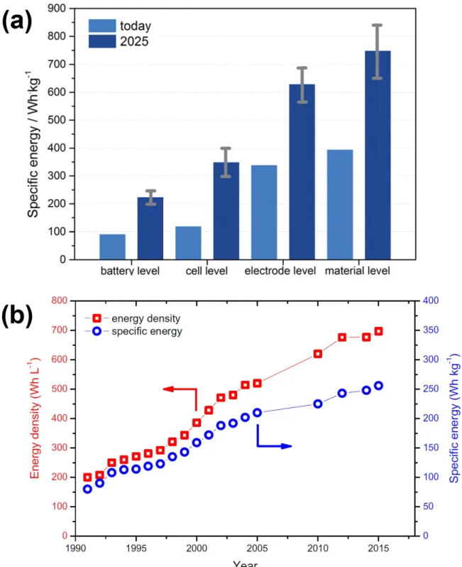
Various and large amount of electronic devices have been supplied to the worldwide from household to industries due to their usability. However, this development has brought us many concerns. Among them, global warming and the depletion of fossil fuels are strongly influencing on our life, for example, rapid climate change, global air pollution, and increasing energy cost. The simple method to prevent the crises is reducing energy consumption. However, because we cannot easily give up our developed and convenient life, the electrification of overall industries from small portable devices to smart electricity grid has been adopted as an irreplaceable global strategy for addressing these serious global issues. Electric vehicle (EV), smart grid involving electrochemical energy storage (EES), and renewable energy generation has been introduced to solve two problems simultaneously. However, the requirements, such as high specific energy and/or energy density, high energy efficiency, long cycle life, low cost per energy and maintenance cost, and eco–friendly, of electrochemical energy storage devices must be enhanced than conventional rechargeable batteries. For example, to facilitate a driving range of more than 500 km for EV, it must be supplied the rechargeable batteries with a practical specific energy in cell level of above 350 Wh kg-1 at least as shown in Figure 1.1a.1-2 Contrastively, the state–
of–the–art lithium–ion batteries (LIBs) only exhibit practical specific energy of 256 Wh kg-1 as shown in Figure 1.1b.3 Therefore, various next generation rechargeable batteries have are suggested to deviate from the fossil fuel industry and for realizing the zero emission of greenhouse effect gases.
Since commercialization in 1991,4 the performance of LIBs have been improved steadily by the development of materials and cell preparing process. LIBs is widely using from mobile phone to EES due to their highest practical specific energy and energy density than other conventional rechargeable batteries. However, even though the performance of LIBs achieves the value similar to their theoretical specific energy or energy density, the LIBs are deficient to satisfy demands for high performance mobile devices, EV, and EES. Therefore, the post lithium–ion batteries (PLIBs) has been introduced for overcoming the insufficiency. One approaches for the improvement are the development of electrode materials with higher capacity for LIBs, such as nickel–rich and over–lithiated (lithium– and manganese–rich) layered oxide as a cathode, and silicon and lithium metal as an anode. (part 1.1.1) The other approaches are the introducing and developing the new electrochemical energy storage system, such as sulfur–based (lithium–sulfur batteries, part 1.1.2) and oxygen–based (lithium–oxygen batteries, part 1.2). Because the prior approaches are based on the LIBs technologies, it has already been introduced partially in commercial products or may be commercialized within the 10 years. On the other
Figure 1.1 (a) The present value and target value (for 500 km per charge) of specific energy for the present and future generation of battery pack, cell, electrodes, and cathode active materials. Reprinted by permission from ref. 2. Copyright 2015 Royal Society of Chemistry. (b) Improvement of the specific energy and energy density of cell level Li–ion batteries (LIBs) from 1991 to 2017. Reprinted by permission from ref. 3. Copyright 2017 Springer Nature.
1.1.1 Post lithium–ion batteries (PLIBs)
Ni–rich layered oxide as a cathode material
The first commercialized LIBs consisted of lithium cobalt oxide (LiCoO2) as a cathode (positive electrode), coke (soft carbon) as an anode (negative electrode), and non–aqueous electrolyte, which was achieved with 80 Wh kg-1, 200 Wh l-1, and the cell voltage of 3.7 V vs. Li/Li+.4-5 To enhance the performance and decrease the cost of LIBs, the cobalt metal in the LiCoO2 of layered oxide structure was substituted other transition metal, such as nickel, manganese, and aluminum. Firstly, LiNi1/3Co1/3Mn1/3O2 was suggested for improving capacity, higher reversibility, and thermal stability.6-7 However, the 1/3 layered oxide exhibited a low degree of increased capacity (ca. 153 mA g-1),7-8 and the content of cobalt must be reduced in the composition of transition metal due to their high cost.
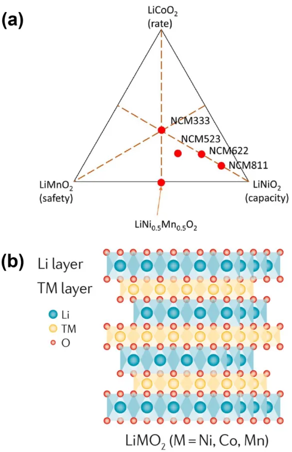
Among layered oxide with various composition of transition metal, nickel–rich layered oxide materials, LiNixCoyMzO2 (M = Mn or Al, x + y + z = 1, x ≥ 0.5) as shown in Figure 1.2a, is attracting an attention, the origin of which can be traced to the early works by the Dahn’s group.9 In fact, LiNi0.8Co0.15Al0.05O2
as thermally stabilized nickel–rich oxide by aluminum are already commercialized.10 All of layered materials have an alternately repeated slabs consisting of Li and transition metal (TM) in the cubic close–packed (ccp) frame of oxygen atoms as shown in Figure 1.2b. The octahedral sites between oxygen frames contain Li and TM ions, in which form the corresponding slab. In addition, there is scattered some Li–TM mixing sites throughout the host structure due to the cation size similarity between Li and Ni ions. The Ni–rich oxide have higher specific capacity owing to their electronic structure; the eg band of TM separates from 2p band of oxygen in contrast with those of LiCoO2, allowing in a higher degree of oxidation without oxygen evolution. As a result, Ni–rich oxide have a higher capacity of 180 ~ 200 Wh kg-1 than that of LiCoO2.11-12 Despite high capacity of Ni–rich oxide, the layered oxide is suffering from the low cyclability, arising from structural and surface change.
Crystallographically, because of the cation size similarity, the TM cation in TM slab preferentially migrates to octahedral site in Li slab during delithiation, resulting in transformation of crystal structure from layered to electrochemically inactive spinel–like and/or cubic (NiO, MnO) structure depending on the degree of delithiation as shown in Figure 1.3a.13-14 This partial structural change occurs during cycling, arising the dropping redox potential, slower rate capability, and capacity fading due to partial shrinkage of c–axis for crystal structure.12-13 Moreover, this change influences on the interfacial instability of Ni–rich oxide. The rock salt cubic structure grows form surface to bulk at initial stage delithiation, and then, this disordered layer maintain the thickness of tens of nanometer over further cycles as shown in Figure 1.3b.12, 15 Despite maintaining the thin thickness, this layer on the surface impedes the lithiation/delithiation process. In addition, this surface deformation also arises the dissolution of TM ions into the electrolyte, resulting in the decreasing reversible capacity and forming
impedance of the Ni–rich oxide. Some strategies, for example, TM doping,10, 18-24 surface coating with chemically/electrochemically stable materials,25-31 and introducing of spinel phases near the surface of oxide or concentration gradient structures,32-33 have been suggested to mitigate the failure of Ni–rich oxide. The developing progress may be a rough journey because thermodynamically preferred phase transition arises the failure of Ni–rich oxide, nonetheless, the developments is expected to continue for searching outstanding solutions owing to their relatively higher possibility of realization.
Li– and Mn– rich (over–lithiated) layered oxide as a cathode material
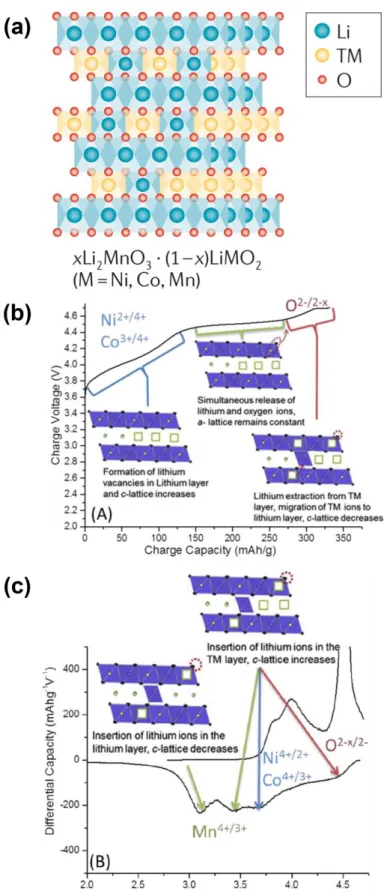
Li– and Mn–rich (over–lithiated) layered oxide (OLO) originates from the early works by the Thackeray groups.34 They exhibited that the Li2MnO3 as a layered rock–salt structure can have electrochemically activity with respect to Li insertion/deinsertion process by acid treatment or electrochemical charging over a high potential of 4.5 V vs. Li/Li+ accompanying with oxygen evolution.35-37 Li2MnO3 can also be represented the layered LiMO2 notated as Li[Li1/3Mn2/3]O2, where consists of interslab octahedral sites occupied by Li+ only and slab octahedral sites occupied by Li+ and Mn4+ (in an atomic ratio of 1:2) as shown in Figure 1.4a. The structure of OLO has described as a single phase solid solution (notation: Li[Lia/3Nib/3Coc/3Mnd/3]O2 (a + b + c + d = 3)) or a composite of two phase (notation: xLi2MnO3·(1-x)LiNiaCobMncO2 (a + b + c = 1)); the rhombohedral phase (R3̅m, LiMO2) and monoclinic phase (C2/m, Li2MnO3).35, 38-39 The delithiation/lithiation process consists of 3 steps in case of electrochemical activation as shown in Figure 1.4b:40 Li+ is extracted from the Li+ only interslab site during the first delithiation until ca. 4.4 V vs. Li/Li+. Until the end of voltage plateau of ca. 4.5 V vs. Li/Li+, the lithium oxide (Li2O) and oxygen gases (O2) releases from the materials, resulting in the formation of MnO2, which could be intercalated subsequently Li+. Beyond activation, above 4.6 V vs.
Li/Li+, Li+ is extracted from the TM slab, and TM ions migrates to the Li only slab. During discharge, as shown in Figure 1.4c, Li+ firstly inserts into the TM slab at high potential. The insertion of Li+ into the Li slab gardually occurs at below 3.5 V (vs. Li/Li+). After the activation, the layered oxide possesses reversible capacity of above 250 mA h g-1 depending on the type of TM. The migration of TM ions into the Li slabs in order to the charge compensation for oxygen causes a voltage hysteresis between delithiation and lithiation.14, 41 In addition, this TM ions gradually make inactive sites and traps the Li+ in the Li slabs during cycle, indicating the capacity and voltage fading of OLO. Furthermore, TM ions trapped sites in the Li slabs impedes the diffusion of Li+ into the TM slab sites, resulting in the structure change from layered to spinel leading to the decreasing redox potential.42-43 TM dissolution also degrades the capacity of OLO owing to the HF attack, which is easily formed at high potential.44 To mitigate the voltage and capacity degradation, the optimization of electrochemical operating condition was introduced, for example, electrochemical activation at low temperature and stepwise potential activation, resulting in the decreased capacity fading due to the interface modification.45-47 The use of alternative electrolyte and additives was also evaluated for the suppressing TM dissolution and surface
reorganization.44 The surface coating and doping, similar to the case for Ni–rich oxide, also exhibited a promising possibility for improved performance of OLO.18, 22-23, 27 In contrast to the Ni–rich oxide, the understanding of the failure mechanism of OLO is in laboratory stage and the relatively cost–effective approaches for the layered oxide are less available for OLO, leading to slower progress towards commercialization.8
Silicon material as an anode material
The enhanced specific energy and/or energy density of PLIBs can be achieved when the specific energy and/or energy density of not only cathode, but also anode is improved. Especially, the alternative anode, such as silicon and lithium metal, must be adopted for satisfying to the demand for EV with the operating range of above 500 km.2, 48 Since the Argonne National Laboratory and General Motors examined the silicon (Si) as anode for lithium–metal sulfide batteries in the 1970s,49-50 Si material have been attracting an intensive attention due to not only their high theoretical specific capacity of above 4000 mA h g-1, but also the low operating voltage of ca. 0.3 V vs. Li/Li+.8, 51 In contrast to the layered oxide or graphite, the lithiation/delithiation process of Si is based on the alloying process via following reaction:
4.4Li + Si ↔ Li4.4Si
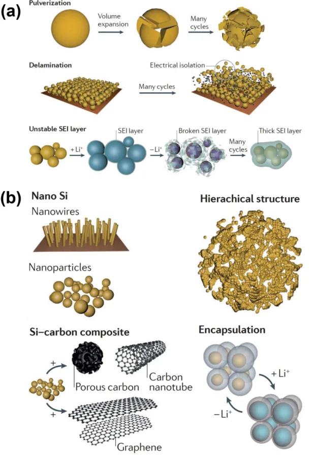
This process is accompanying with the huge volumetric change of above 400 %.51 This volume expansion cause the severe drawbacks, such as pulverization, delamination from current collector, and the thick formation of solid–electrolyte interphase (SEI), which interrupts the commercialization of Si anode for PLIBs as shown in Figure 1.5a.8, 51-52 At the initial stage of research toward Si materials, nanostructured, carbon composite electrode, and effective binder capable of accommodating huge volume change have been introduced to reduce the pulverization and delamination as shown in Figure 1.5b.52-66 Moreover, the new designed electrolyte has been also suggested to maintain the stable SEI.67-
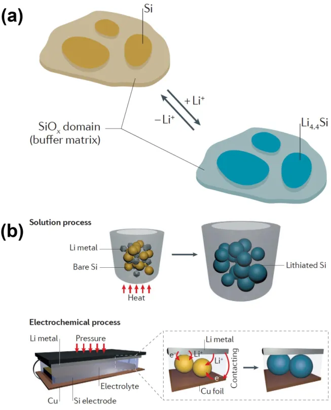
69 In spite of the significant improved performance of Si used with the solutions, the silicon monoxide (SiOx, x ≈ 1) has been adopted for the battery industry instead of the above mentioned solutions owing to their more reasonable price and reliable production quality as shown in Figure 1.6a.70-71 However, because the poor initial Coulombic efficiency (ICE), SiOx has been only used less 5 wt% in a blended form with graphite. The low ICE requires the additional cathode materials, leading to the loss in the specific energy and/or energy density of the entire cell. In this context, attempts to the manufacturing the prelithiated Si anode using solution or electrochemical process has been increasing as shown in Figure 1.6b.72-74 Combining the prior method, such as nanostructured electrode, binder tolerant to volume change, electrolyte forming stable SEI, and pre–lithiated Si, could be achieved the high ICE,
system is still insufficient to satisfy the demands for EV.
Lithium metal as an anode material
Since Stanley Whittingham at Exxon was conceptually introduced for the Li–TiS2 system in 1970s,75 Li metal anode had been intensively for Li batteries. When the Li batteries containing a Li metal anode and a MoS2 cathode was commercialized firstly in the late 1980s by Moli Energy,76-77 this cylindrical–
type cells exhibited a hundreds of cycle performance, therefore, millions of cells were sold to the market.
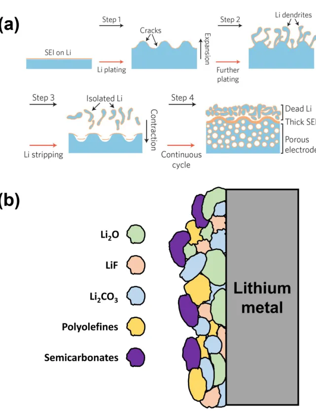
However, this batteries became notorious for safety issues, including frequent and severe fires arose from the dendrite formation, to the public.78-79 At that time, Sony launched the Li–ion batteries containing carbonaceous anodes to replace Li metal successfully, and this cell has been exhibited high reliability until now.4 As a result, the entire Li batteries using Li metal anode was recalled and disappeared without any trace from the market, furthermore, the research related with Li metal anode has also been drastically reduced. Nowadays, the increasing demands for higher specific energy and/or energy density of rechargeable batteries is revitalizing the research on the Li metal anode again owing to their highest theoretical capacity (3860 mA h g-1, 2061 mA h cm-3) and lowest electrochemical potential (-3.04 V vs. SHE) than all possible alkali metal. To become a viable technology, the Li anode is need to surmount the tremendous drawbacks: dendrite growth and unstable interface, which is complicate correlation with the failure of Li metal anode as shown in Figure 1.7a.78-81 The dendrite growth is related with inhomogeneous dissolution and plating, arose from the non–uniform native oxide and current density on the Li metal surface. This dendrite grows on the Li metal surface during the Li stripping/plating, resulting in the internal short circuit and the vigorous morphological change, such as porous surface structure and dead lithium. Furthermore, this morphological change leads to the formidable decomposition of electrolyte, resulting in the thick passivation retarding the Li+ diffusion and depletion of electrolyte. The volume change of Li metal anode also impedes the stable cyclability due to their reaction mechanism analogous to conversion and alloying materials, in contrast to intercalation materials. To deal with these issues, it need to obtain a profound insight toward interfacial chemistries, stripping/plating behavior of Li, and the entangled interaction among them. To understand the interfacial chemistry, ever since Emanuel Peled and Doron Aurbach as a pioneer have firstly studied toward component of interfacial layer, the SEI on the Li metal has been investigated with various electrolyte.82-85 The passivation by the ‘mosaic structured’ SEI suppresses the continuous decomposition of electrolyte and make it available to stably operate a Li metal containing cell under a highly reductive circumstance as shown in Figure 1.7b. However, the passivation is vulnerable to considerable interface fluctuation, leading to continuously forming SEI on the Li metal and exhausting the electrolyte. To resolve the unstable interface, various electrolyte engineering has been introduced, for example, ether–
based electrolyte,86-94 salt and gaseous form additive,95-103 fluorinated or organic compound,103-112 self–
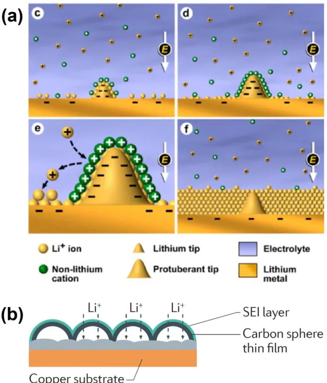
healing electrostatic shield as shown in Figure 1.8a,112-113 and high salt concentration.114-115 Instead of
the consumable techniques, the permanent protective layer has been also introduced, such as artificial SEI,102-103, 116-123 artificial layer for isolating and controlling the interface between Li metal and electrolyte as shown in Figure 1.8a,124-132 scaffolds or morphological change for guiding the Li stripping/plating,133-138 and solid electrolyte.139-143 Despite these suggested technologies for use of Li metal as an anode in Li–based batteries are enhanced the performance of Li metal anode, it need to verify the safety and performance corresponding to the level of industries to prevent the prior misstep.
However, the investigation and improvement toward Li metal anode must be retained owing to being beneficial in the long run for not only Li–metal batteries but also new Li–based battery systems, such as lithium–sulfur (Li–S) and lithium–oxygen (Li–O2) batteries.
Figure 1.2 (a) Phase diagram of the ternary system between LiNiO2, LiCoO2, and LiMnO2 with some representative composition. Reprinted by permission from ref. 12. Copyright 2017 The Electrochemical Society. (b) Crystal structure of layered LiMO2 (M = Ni, Co, and/or Mn). Reprinted by permission from ref. 8. Copyright 2016 Springer Nature.
Figure 1.3 (a) Proposed phase transition process from layered to spinel–like structure of TM over charging. Reprinted by permission from ref. 8. Copyright 2016 Springer Nature. (b) Partial crystal structure change of LiNi0.5Co0.2Mn0.3O2 on the surface region after 50 cycles. Reprinted by permission from ref. 15. Copyright 2013 John Wiley & Sons, Inc..
Figure 1.4 (a) Crystal structure of over–lithiated oxide (OLO). Reprinted by permission from ref. 8.
Copyright 2016 Springer Nature. (b) Voltage profile during charge and (c) dQ/dV plot during discharge of 1st cycle for 0.35LiMn2O3·0.65Li(Ni0.35Co0.20Mn0.45)O2. Reprinted by permission from ref. 12.
Copyright 2017 The Electrochemical Society.
Figure 1.5 Schematic diagrams (a) for the failure mechanism of Si anode and (b) of nanostructured Si anodes and their composites. Reprinted by permission from ref. 8. Copyright 2016 Springer Nature.
Figure 1.6 Schematic diagrams of (a) reaction process toward SiOx anode and (b) pre–lithiated Si anodes via a solution and electrochemical processes. Reprinted by permission from ref. 8. Copyright 2016 Springer Nature.
Figure 1.7 Schematic diagrams of (a) the failure mechanism toward Li metal during cycling. Reprinted by permission from ref. 79. Copyright 2017 Springer Nature. (b) Schematic cross–section diagram of the “mosaic” morphology of solid–electrolyte interphase (SEI) on the Li metal.
Figure 1.8 Schematic diagram of (a) the self–healing electrostatic shield (SHES) mechanism toward Li metal during cycling. Reprinted by permission from ref. 113. Copyright 2013 American Chemical Society. (b) Schematic cross–section diagram of the artificial layer for isolating and controlling the interface between Li metal and electrolyte. Reprinted by permission from ref. 8. Copyright 2016 Springer Nature.
1.1.2 Sulfur–based batteries (Li–S batteries)
To surpass the limiting specific energy of LIBs, the weight of active materials and inactive materials, such as host materials and conductive carbon, must be reduced. In this context, lighter elements as a redox center have been considered to electrode material for new electrochemical energy storage system.
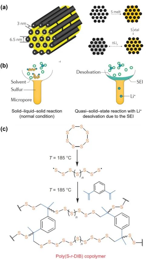
Among these new electrochemical energy storage system to replace the Li–ion batteries, sulfur–based batteries is one of the most promising energy storage system owing to their high theoretical specific energy, low cost, and abundant reserves. Ever since Herbet and Ulam at Electric Tech Corp. introduced the sulfur as a cathode for electrochemical cell conceptually in 1962,144 alkali metal–sulfur energy storage system, such as sodium–sulfur (Na–S) and lithium–sulfur (Li–S) batteries,145-146 had been investigated but were abandoned soon. However, since the demand for the high energy storage system has begun to increase, the intensive research toward Li–S batteries (LSBs) has been revitalized. The reason is that the cell operates at room temperature in contrast to Na–S batteries to operate at a temperature of 300–350 ℃ and have the theoretical specific and energy density of 2500 W h kg-1 and 2800 W h l-1.147 Especially, PolyPlus and Sion Power Corporation are developing the proto–type LSBs for unmanned vehicles and military–purpose devices. However, LSBs has been still not materialized the promising energy storage devices to overtake commercialized LIBs owing to their several limitation inherent in the reaction chemistry:8, 147 (1) insulating nature of sulfur leading to poor reversibility and low rate capability; (2) soluble polysulfide intermediates (Li2Sx, 3 ≤ x ≤ 6) leading to the shuttle phenomenon; and (3) unstable interface between Li and electrolyte. One approaches to dissolution of polysulfides is the designing sulfur cathode structure. The encapsulating technique with conductive porous materials to sulfur has been introduced to resolve the sulfur cathode related two problems simultaneously.148-151 The conductive materials, for example, mesoporous activated carbon fibers or nano–sized assemblies, not only provide the electron conducting path for insulating sulfur, but also reduce the dissolution of polysulfide as shown in Figure 1.9a. This dissolution suppressing progresses via the depleting contact area between polysulfide and electrotype or the enhancing binding affinity to polysulfides. The introducing LiNO3 in the electrolyte can be exhibited not only the inhibiting effect of the dissolution, but also catalytic effect for the redox reaction of sulfur.95, 152 Moreover, the SEI formed on the sulfur filling in micropore can be prevented the dissolution as shown in Figure 1.9b.153-154 The appropriate content of sulfur in micropore excludes accessing other electrolyte solvent molecules to the micropore, leading to the redox reaction of polysulfides in solid phase, so called the quasi–solid–state reaction with desolvated Li+. The relatively insoluble small sulfur allotrope and chemically bound sulfur to polymer can be also suppress the dissolution.155-157 In a practical point of view, the low energy density arose from the low density and loading amount of sulfur must be surpassed by designing high density electrode accompanying with alleviating polysulfide dissolution. Furthermore, the limitation of Li metal
drawbacks of LSBs will be resolved, the specific energy and/or energy density of LSBs in full package scale of batteries may be still insufficient to satisfy the demand for high energy needed devices.
Figure 1.9 (a) Schematic diagram of the carbon encapsulated S (yellow) electrode. Reprinted by permission from ref. 148. Copyright 2009 Springer Nature. (b) Schematic diagram for comparison of lithiation reaction in Li–S batteries (LSB) depending on Li+ desolvation. Reprinted by permission from ref. 8. Copyright 2016 Springer Nature. (c) Synthetic process diagram for copolymerization of S8 with 1,3–diisopro–penylbenzene (DIB) to form chemically stable sulfur polymer. Reprinted by permission
1.2 Lithium–Oxygen batteries (Li–O2 batteries)
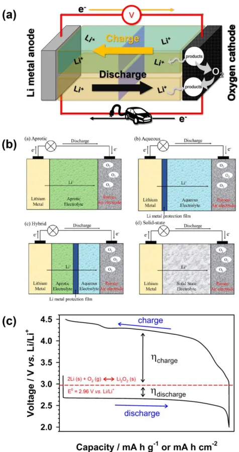
Lithium–oxygen (Li–O2) batteries has been received large attention as the most attractive energy storage device due to their high theoretical energy density (ca. 11 kW kg-1) which is superior to that of any other next generation rechargeable batteries.158-159 The Li–O2 batteries is typically comprised of a Li metal anode, oxygen electrode with high surface area, and Li–ion conducting electrolyte as shown in Figure 11.1a. The Li–O2 batteries has been classified into four categories based on the electrolyte;
non–aqueous, aqueous, hybrid, and all–solid–state batteries depending on the type of electrolyte as shown in Figure 11.1b. This classification depending on the electrolytes is used because the electrolyte influence on the reaction kinetics and reaction process of Li–O2 batteries. Among them, liquid–state electrolyte–based Li–O2 batteries including non–aqueous and aqueous systems have been investigated intensively due to their higher ionic conductivity than that of solid electrolyte–based system. Between the liquid electrolytes, the non–aqueous electrolyte for Li–O2 batteries is more feasible than aqueous electrolyte to use of Li metal at the anode without safety issue. Moreover, the Li–O2 batteries with non–
aqueous electrolyte has higher theoretical energy density than that of Li–O2 batteries with aqueous electrolyte because of the electrolyte participated in the reaction of Li–O2 batteries.
The reaction mechanism of Li–O2 batteries showing the voltage profile as shown in Figure 1.11c is based on the oxidation reaction of Li metal via following reaction with a redox potential of 2.96 V vs.
Li/Li+:160
Anode (oxidation during discharge): 2Li (solid) ↔ 2Li+ + 2e- Cathode (reduction during discharge): O2 (gas) + 2e- ↔ O22-
Overall reaction: 2Li (solid) + O2 (gas) ↔ Li2O2 (solid)
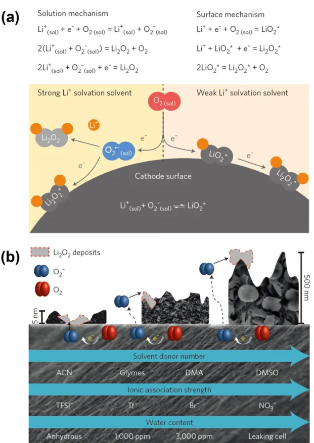
This reaction is in case of Li–O2 batteries with non–aqueous electrolyte. The forward reaction to form lithium peroxide (Li2O2) is named as oxygen reduction reaction (ORR) and the backward reaction for the decomposition of Li2O2 is named as oxygen evolution reaction (OER). These two processes are main process that governing the electrochemical performance of Li–O2 batteries. The non–aqueous electrolyte do not directly participates the reaction of the Li–O2 batteries in contrast with the aqueous electrolyte, but strongly influences on the reaction process. Consequently, the electrochemical process of Li–O2 batteries is governed by the properties of electrolyte. In the non–aqueous electrolyte, the electrochemical process of forming Li2O2 occurs via two routes: the surface route and the solution route as shown in Figure 1.11a.161-162 On the first stage of discharge, a lithium superoxide (LiO2) forms after the electrochemical reduction of oxygen. This LiO2 is slightly soluble into the non–aqueous solvent;
therefore, the solubility of LiO2, which is according to Pearson’s hard–soft acid–bases (HSAB) theory, determines the pathway of further reaction to form a Li2O2. A LiO2 is less soluble into the solvent with
low donor number (DN), therefore, the adsorbed LiO2 onto the oxygen electrode surface is mainly reduces to Li2O2 by electrochemical process. On the other hands, in the solvent with high DN, LiO2 is more soluble into the solvent due to enhanced stability of the complex (Li+–(solvent)n–O2-) by the high DN solvents, and disproportionate themselves into Li2O2.163 In addition, because the polarization and surface area of oxygen electrode less influence on the solution process, high DN solvents improve the discharge capacity of Li–O2 batteries as shown in Figure 1.11b.161-162 Interestingly, the Li salt anion with high DN can also increases the DN of solvent having relatively low DN, leading to being as if the properties of high DN solvent.162, 164 Moreover, the contents of water in the Li–O2 batteries influences the discharge reaction mechanism that determines the large toroidal formation leading to the high discharge capacity.162, 165-166 However, the electrolytes possessing the high DN is not always good for the enhanced performance of Li–O2 batteries due to the needs for the considering other properties of electrolytes simultaneously. The non–aqueous electrolyte is needed to the following attributes for the ideal reaction of Li–O2 batteries:160
(a) High chemical stability against reactive oxygen derivatives, such as superoxide (O2-), peroxide (O22-), its adduct (LiO2 and Li2O2), and various additives
(b) High electrochemical stability (c) High oxygen solubility
(d) High diffusivity of oxygen and Li+
(e) Low volatility and high boiling point for minimizing evaporation (f) Sufficiently high conductivity for desired rate capability
To achieve high electrochemical performance of Li–O2 batteries, the various non–aqueous electrolytes have been investigated for appropriate solvents, salts, and additives. The carbonate–based solvents, such as dimethyl carbonate (DMC), ethyl methyl carbonate (EMC), ethylene carbonate (EC), and propylene carbonate (PC), were firstly used as an electrolyte solvent for Li–O2 batteries.167 However, these solvents exhibited the low stability against reactive oxygen derivatives, as a results, the reaction of Li–O2 batteries with carbonate–based electrolytes mainly forms lithium carbonate (Li2O3) and lithium alkylcarbonate (RO–(C=O)–OLi) rather than the Li2O2.168 To substitute the carbonate–based electrolyte, ether–based electrolytes were suggested and exhibited the enhanced electrochemical performance of Li–O2 batteries than that of Li–O2 batteries with carbonate–based electrolyte. The ether–
based electrolyte is mainly used 1,2–dimethoxyethane (DME, monoglyme, G1), 1–Methoxy–2–(2–
methoxyethoxy)ethnae (diglyme, G2), 1,2–Bis(2–methoxyethoxy)ethane (triglyme, G3), or 2,5,8,11,14–Pentaoxapentadecane (TEGDME, tetraglyme, G4).169-170 These solvent as an electrolyte for Li–O2 batteries have been widely used due to their stability against reactive oxygen species, high
wetting property for electrodes. However, although the Li–O2 batteries with ether–based electrolyte showed the operation over numerous cycles and the ether is relatively insensitive toward nucleophilic O2- attack than the carbonates, the ether–base solvent were not completely inert toward reactive oxygen species. The high DN solvent, such as dimethylformamide (DMF),171 N,N–dimethylacetamide (DMAc),172-173 dimethyl sulfoxide (DMSO),163, 174-175 and ethyl methyl sulfone (EMS),176 as a electrolyte solvent for Li–O2 batteries have been suggested and demonstrated outstanding performance of Li–O2
batteries. However, these solvents still suffer from the necleophilic O2- attack, instability against Li2O2, or side reaction with Li metal.171, 176-185 Unfortunately, in spite of intensive research toward the ideal electrolyte, the chemical stability against reactive oxygen derivatives still remain the key challenging issue.
The main drawbacks of Li–O2 batteries is two: chemical/electrochemical stability related with the prior mentioned electrolyte and reaction kinetic related with ORR and OER. Especially, the high polarization of Li–O2 batteries is main issue for achieving longer cycle performance due to sluggish kinetics of the OER. Furthermore, the high charging potential accelerates the decomposition of electrolyte and oxygen electrode corrosion, resulting in poor cycle performance of Li–O2 batteries. To overcome the limitation, various solid catalysts have been suggested to facilitate the OER reaction as shown in Figure 1.12a and b. These catalysts, such as noble metals,186-188 transition metal oxides,189-192 noble metal–metal oxide or organometallic composite,193-196 and modified carbon–based catalysts,197-198 decrease the charging overpotential than that of pristine porous carbon electrode. In spite of their usefulness, solid catalysts encounter the two drawbacks: the spatial constraint and unexpected reaction.186 The solid catalysts reacts only at the interfaces between catalyst surface and the solid Li2O2, therefore, a large amount of catalyst is required. In addition, some catalysts not only accelerates the decomposition of desired discharge products, but also the cell components like the electrolyte.
Therefore, attempt to surmount the limitation of solid catalysts, the red–ox mediator as a soluble catalyst has been introduced in the electrolytes of Li–O2 batteries as shown in Figure 1.12c and d. A tetrathiafulvalene (TTF) was first reported and could decrease the polarization of OER in Li–O2
batteries.199 Furthermore, the various redox mediator has been suggested, such as redox organic material [5,10–dihydro–5,10–dimethylphenazine (DMPZ), 10–methylphenothiazine (MPT), tris(4–
(diethylamino)phenyl)amine (TDPA), 2,2,6,6–tetramethyl–1–piperidinyloxy (TEMPO) and its derivatives],200-205 halide–based inorganic salt (cesium iodide (CsI), indium iodide (InI3), lithium bromide (LiBr), lithium iodide (LiI)],206-210 and metal–organic compound [cobalt bis(terpyridine) (Co(Terp)2) and iron phthalocyanine (FePc)],211-212 as a desirable soluble catalysts for OER in the Li–
O2 batteries. These redox mediators decreased the overpotential efficiently and exhibited extended cycle performance of Li–O2 batteries. However, the redox mediator is also faced with the limitation; their catalytic activity gradually degrades as cycles progress, leading to a progressively increasing polarization as cycle number increasing. This increasing polarization in the Li–O2 batteries with a redox
mediator has been regarded to arise from the shuttle effect, which charge transfer phenomena via the electrolyte by shuttle agent.210, 213-214 This effect influences on the concentration of redox mediator radicals near to the oxygen electrode, resulting in increasing the polarization. Therefore, the redox mediator for the Li–O2 batteries still requires further enhancement.
Figure 1.10 (a) Schematic diagram of Li–O2 batteries with the reaction process during discharge/charge.
(b) Schematic diagram of the various type of Li–O2 batteries depending on the electrolyte system.
Reprinted by permission from ref. 159. Copyright 2014 American Chemical Society. (c) Typical galvanostatic voltage profile of Li–O2 batteries.
Figure 1.11 Schematic diagrams of (a) reduction mechanism in the Li–O2 batteries at low overpotential and (b) the mechanisms of surface and solution growth in the Li–O2 batteries depending on the electrolyte solvents. Reprinted by permission from ref. 162. Copyright 2016 Springer Nature.
Figure 1.12 (a) Galvanonstatic voltage profile (left) and differential electrochemical mass spectroscopy (DEMS, right) analysis of Li–O2 cell loaded Ir/rGO catalysts. Reprinted by permission from ref. 195. Copyright 2016 Springer Nature. (b) Schematic diagram for the reaction mechanism of the Li–O2 cell loaded Mn3O4/Pd catalysts. Reprinted by permission from ref. 196. Copyright 2013 Royal Society of Chemistry. (c) Galvanostatic voltage profile of Li–O2 cell containing TTF as a redox mediator for OER or TTF–free at 1st cycle (left), and of Li–O2 cell containing TTF during cycling (right).
Reprinted by permission from ref. 199. Copyright 2013 Springer Nature. (d) Schematic diagram for the reaction mechanism of the Li–O2 cell containing TEMPO as a redox mediator. Reprinted by permission from (d) ref. 201. Copyright 2014 American Chemical Society.
1.3 Research motivation
This doctoral dissertation is focused on the study of failure mechanism of the non–aqueous Li–O2
batteries with redox mediator. Especially, this dissertation is dealing with how to degrade the electrochemical activity of redox mediator in the electrolyte for Li–O2 batteries, furthermore, suggests the method of sustaining electrochemical activity of redox mediator in the Li–O2 batteries based on the analyzed results. The shuttle effect concept is not sufficient to explain the gradually increasing overpotential of Li–O2 batteries over the cycling. The polarization of Li–O2 batteries with redox mediator is almost correlated with the redox potential of redox mediator, because the redox mediator in the electrolyte for Li–O2 batteries firstly oxidizes during electrochemical process. Therefore, the increasing polarization is related with the electrochemically inert passivation of electrode or the loss of electro–active species by side reaction. In addition, during shuttling phenomenon, there is no loss of electrochemical species: redox mediator radicals produced on the oxygen electrode diffuse out to Li metal anode, and are reverted to the previous form of redox mediator by Li metal anode. The returned redox mediators then diffuse back to the oxygen electrode. Although there is the charge shuttling via the redox mediator in the electrolyte, the shuttle agents maintain their electro–activity and concentration on the oxygen electrode. In case of lithium–sulfur batteries (Li–S batteries), the potential of Li–S batteries remain a constant during shuttle effect. One possibility to losing redox mediator activity or concentration is the side reaction of redox mediator on the oxygen electrode, which related with electrochemical reversibility and/or radical stability of redox mediator. The redox mediator may losses their electrochemical activity due to the side reaction arisen from high reactivity of their radical or exposure to highly reactive oxygen derivatives. The other possibility is the side reaction on the Li metal anode. In case of some redox mediators, such as FePc211 and TEMPO214, the clues of side reaction toward Li metal anode were observed without precise explain toward failure mechanism. These two origin for the failure of Li–O2 batteries with a redox mediator arose from the cell components can also observed from comparing the electrochemical performance of Li–O2 batteries with a TTF.199, 201 The Li–O2 batteries with TTF using nanoporous gold, DMSO, and LFP as an oxygen cathode, electrolyte, and anode, respectively, shows the stable performance, whereas the increasing polarization of charging potential was observed in the Li–O2 batteries using porous carbon, 1–Methoxy–2–(2–
methoxyethoxy)ethnae (diglyme), and Li metal as an oxygen cathode, electrolyte, and anode, respectively.
Therefore, this dissertation analyzes the correlation between redox mediator and cell components, such as electrolyte solvent and Li metal, and is proved that the side reaction between them strongly influences on the failure of Li–O2 batteries with a redox mediator.