i
CERTIFICATION OF APPROVAL
GEOPOLYMER BASED OIL WELL CEMENTING SYSTEM USING MIRHA
By
MUHAMMAD ZULIQRAM BIN MAMSOR
A project dissertation submitted to the Petroleum Engineering Program Universiti Teknologi PETRONAS In partial fulfillment of the requirement for the
Bachelor of Engineering (Hons) (Petroleum Engineering)
Approved:
__________________________
Assoc. Prof. Dr. Nasir Shafiq Project Supervisor
UNIVERSITI TEKNOLOGI PETRONAS TRONOH, PERAK
MAY 2013
ii
CERTIFICATION OF ORIGINALITY
This is to certify that I am responsible for the work submitted in this project, that the original work is my own except as specified in the references and acknowledgements, and that the original work contained herein have not been undertaken or done by unspecified sources or persons.
__________________________
Muhammad Zuliqram Bin Mamsor
iii
ABSTRACT
The main objectives of this research are: (1) to find an alternative for oil well cementing system by using Microwave Incinerated Rice Husk Ash (MIRHA) geopolymer, (2) improve strength of oil well cementing system (3) introduce a green technology of oil well cementing system (4) make use of the fly ash and rice husk ash produced in industries. MIRHA was found to provide a competitive strength compared to the Portland cement in other application than oil well cementing. Therefore in this research, MIRHA is used to produce suitable geopolymer cement that can be used for oil well cementing system. Six models of geopolymer cement using MIRHA have been developed throughout this research in order to find the most ideal to be used in oil well cementing system in terms of its compressive strength. The ideal geopolymer cement in this research should provide competitive strength as given by the API cement classes used in oil well cementing system. Oil wells cement analysis, slurry preparation and compressive strength factors have been taken into consideration throughout the development of this research to ensure its successfulness.
Geopolymer sample B in this research has shown impressive compressive strength for 24hours curing at 80F which is 2085.64 psi. This is 76.01% improvement of compressive strength compared to API cement class G and 95.91% improvement of compressive strength compared to API cement class H with the same curing time and temperature. Other than that, geopolymer samples A, C and D also has shown improvement in compressive strength. Therefore, we can say that MIRHA geopolymer have better compressive strength than API cement class G and H and thus, MIRHA geopolymer can replace API cement classes G and H in oil well cementing system as basic cement from surface to 8000ft of depth. All of the research’s objectives were successfully achieved. Detailed results can be found throughout this paper.
iv
ACKNOWLEDGEMENTS
First and foremost the author would like to express his profound appreciation and deepest gratitude to God Almighty for His blessing and granted strength and health to be able to complete this project. Thank you to family and friends who have helped me from the very beginning until the submission of this report.
Special thanks to my supervisor, Assoc. Prof. Dr. Nasir Shafiq for his supervision, guidance valuable advice, continuous support and encouragement to complete this research.
The author would like to thank Petroleum & Geoscience Engineering Department and Civil Engineering Department for the facilities, in using the laboratory and equipment.
The author wishes to extend his appreciation to laboratory technician for the help and guidance in conducting experiments.
The appreciation also goes to Universiti Teknologi PETRONAS in providing necessary assets and resources for the success of this project. Last but not least, the author would like to express deepest appreciation toward all course mates in giving priceless support, encouragement and knowledge to complete this project.
v TABLE OF CONTENTS
Certification of Approval ... i
Certification of Originality ... ii
Abstract ... iii
Acknowledgements ... iv
List of Figures ... vii
List of Tables ... viii
Chapter 1: Project Background ...1
1.1 Background of Study ...1
1.2 Problem Statement ...2
1.2.1 Problem Identification ...2
1.2.2 Significance of the Project ...2
1.3 Objective and Scope of Study ...3
1.3.1 Objectives of the Project ...3
1.3.2 Scope of Study ...3
1.4 Relevancy of the Project ...4
1.5 Feasibility of the Project Within Scope and Time Frame ...5
Chapter 2: Literature Review ...6
2.1 Oil Wells Cement Analysis ...6
2.2 Slurry Preparation ...12
2.3 Compressive Strength ...16
Chapter 3: Methodology ...19
3.1 Research Methodology ...19
3.2 Project Activities ...20
3.3 Key Milestones ...21
vi
3.4 Gantt Chart ...21
3.5 Experiments ...22
3.5.1 Slurry Preparation ...22
3.5.2 Oven Curing ...25
3.5.3 Compressive Strength Test ...25
3.6 Tools and Equipment ...26
Chapter 4: Result and Discussion ...27
4.1 Compressive Strength Test ...27
Chapter 5: Conclusion and Recommendation ...31
References ...33
Appendix ...34
Appendix 1: Gantt Chart ...34
vii LIST OF FIGURES
Figure 1: Fractured Test Specimen at Failure ... 188
Figure 2: Example of compressive strength test results ... 188
Figure 3: Methodology Flow Chart ... 199
Figure 4: Flow chart of experiment ... 222
Figure 5: Composition of geopolymer ... 222
Figure 6: From left is sodium hydroxide, sodium silicate, MIRHA and fly ash used for slurry design ... 23
Figure 7: Mixing process of slurry ... 223
Figure 8: Slurry is put into 50mm x 50mm mold ... 223
Figure 9: Molded slurry is put into oven for curing process ... 223
Figure 10: Compressive strength comparison ... 228
Figure 11: Compressive strength improvement compared to API cement class G ... 229
Figure 12: Compressive strength improvement compared to API cement class H ... 30
viii LIST OF TABLES
Table 1: API cement classes ... 8
Table 2: Chemical requirements for API cements ... 9
Table 3: Physical requirements for API cements ... 10
Table 4: Physical requirements of various cement classes ... 11
Table 5: Summary of oil well cementing additives ... 13
Table 6: Summary of oil well cementing additives (continued) ... 14
Table 7: Mix proportions employed ... 15
Table 8: Fly ash and MIRHA chemical compositions ... 166
Table 9: Key milestones ... 211
Table 10: Composition of cement slurries employed in this research ... 244
Table 11: Required materials for cement slurry design ... 266
Table 12: Tools and equipment used ... 266
Table 13: Compressive strength results... 267
1
CHAPTER 1
PROJECT BACKGROUND
1.1 Background of Study
One of the most crucial parts of well completion is well cementing process. Well cementing process is a process where cement will be filled and seals the annulus between the casing string and the drilled hole. Well cementing was done based on 3 purposes which are: (1) zone isolation and segregation, (2) corrosion control, and (3) formation stability and pipe strength improvement. Cement is used because it will form a nearly impermeable and strong extremely strong seal from thin slurry. The properties and behavior of the cement slurry will be varies based on the components and additives used to form the cement slurry itself. Different components used or same components but differs in proportion will affect the cement slurry properties and behavior.
Conventional well cementing in oil industry mostly used the Portland type cement.
Portland cement is made of limestone and either clay or shale and roasted at 2600 to 3000oF. From the high temperature process, the mixture turn into another material called clinker cement (Smith D. , 1990). After the roasting step, the rough clinker produced will be ground to the specified size define by the cement grade.
The first cement used oil and gas industry was recorded as water shutoff attempt in 1903, California (Smith R. ). During that time, the cement was hand mixed and run in a dump bailer to spot a plug (Smith R. )Pumping the cement down a well was recognized to give benefits and was first used in 1910 (Smith R. )
As time passes, engineers are still looking the best cementing system to improve the benefits that has been discovered since the early era of the oil and gas industry. Thus, this research is will be one of the efforts to improve the oil well cementing system and will be discussed more throughout this paper.
2 1.2 Problem Statement
1.2.1 Problem Identification
In conventional well cementing process, cement will be added with water and other additives to let to react. The mixture of all stated components will release heat during the reaction. However, there will be high temperature below the surface and will be exposed to the cement gel before it is hardened. It means that instead of releasing heat during the reaction, it will also receive heat from the surrounding in which will result in its final product and in this case, the hardened well cement. The well cement could be cracking in any time if wrong measurements and precautions were taken. Thus, if there are cracks in the well cement, it will lose its function especially to prevent water intrusion into the well.
Therefore, this research is conducted to find an alternative for the conventional well cementing process with improve benefits.
1.2.2 Significance of Project
This research is very significant in order to provide a better well cementing process.
Instead of using Portland cement for the well cementing, we could use geopolymer cement since it will give us more benefits. Geopolymer cement does not offer only its benefits in terms of its strength, it will also offer its green technology because it will not use any cement. The proposed geopolymer materials that will be used in this research are fly ash and rice husk ash. Both are waste materials that can be turned into more beneficial product.
Thus, by conducting this project, green technology can be promoted by using waste materials which are fly ash and rice husk ash to provide a new oil well cementing system since its will provide a greater strength, than the conventional Portland cement used.
3 1.3 Objective and Scope of Study
1.3.1 Objectives
The main objective of this research is to find an alternative for conventional oil well cementing system. Instead of using Portland cement, we could use geopolymer cement.
Microwave Incinerated Rice Husk Ash (MIRHA) was found to provide a competitive strength compared to the Portland cement. Thus, MIRHA will be used to produce suitable geopolymer cement that can be used for oil well cementing system and by the end of this research this product will offers:
1. A geopolymer cement using MIRHA.
2. Improved strength of oil well cementing system.
3. A green technology of well cementing system.
4. Make use of the fly ash and rice husk ash produced in industries.
1.3.2 Scope of Study
The overall research plan is to produce a variety mixture of geopolymer cements using MIRHA and measure its strength. This procedure will be conducted to find the best geolpoymer cement that can be used for oil well cementing system. Due to the limited time, only few factors will be taken into consideration and they are as follows;
1. Oil well cement analysis 2. Slurry preparation 3. Compressive strength
4 1.4 Relevancy of the Project
This research will be very relevant judging from certain criteria and circumstances.
Through the previous points of this paper, this research will bring an improvement in cementing of oil well. This research will find a new way of oil well cementing system.
Well cementing is always a crucial part in oil and gas industries. A better well cementing will affect the well performance. Since they are a lot of production of waste i.e. fly ash and rice husk ash, and there are researches about geopolymer cement using this material, we have to make an effort to find either this geopolymer cement can also be used as oil well cement. A suitable proportion of mentioned wastes, with an additional of some additives may produce the same strength as conventional cement used for oil well cementing system nowadays.
Besides that, the costing of using conventional cementing system also is an issue.
Portland cement has to be bought before it can be used for oil well cementing operation. Of course this Portland cement has its price because it is purposely produce for cementing. Fly ash and rice husk ash in the other hand were not produced for any purposes. They are the waste materials in the industries. The used of these materials will save a lot of money for oil well cementing process if they can provide the same function with improve benefits as Portland cement use.
Thus, from my point of view, the development of this research is very relevant to overcome the issues arise from conventional cementing system.
5
1.5 Feasibility of the Project within the Scope and Time frame
The completion and development of this research is feasible judging from the objectives and the scope of studies as mentioned earlier. Approximation period of time to complete this research is 8 months.
Throughout the 8 months, the author will focus more into making various models of geopolymer cement using fly ash as the main component and apply the Microwave Incinerated Rice Husk Ash technique together with other additives to find the most suitable to be used for oil well cementing system. In addition, the models and testing can be done in lab in UTP.
6
CHAPTER 2
LITERATURE REVIEW
This literature review will theoretically covers every elements and foundation of the research. The objective of this research is to produce a geopolymer cement using MIRHA for oil well cementing system. Thus, previous studies related to the scope of work of this research will be discussed in this section.
2.1 Oil Wells Cement Analysis
The most important thing before proceed with this project is to gather all of the oil well cement analysis. With the valid knowledge of past researches about the oil well cementing, we know what are the things that have to be considered in the development of this geopolymer oil well cement using MIRHA project.
Basically, there are two main parts of well cementing which are primary cementing and remedial cementing. The objective of the primary cementing is to provide zonal isolation. On the other hand, the remedial cementing job will be done to correct problems occur due to the primary cementing job. Well cementing is a process where slurry of cement and water were mixed and pumped through the casing to critical points in the annulus around the casing or in the open hole below the casing string (Crook, 2006). The main principals of cementing are restrict fluid movement between the formations and to bond and support casing.
If this is achieved effectively, the economic, liability, safety, government regulations, and other requirements imposed during the life of the well will be met (Crook, 2006).
Although zonal isolation is not directly related to the production, it has to be done effectively so that production and well stimulation can be conducted. From this, it is crystal clear that the success of the well will be affected directly by the cementing job.
7
Crook Ron in his writing provides the steps required in order to achieve successful cementing job as follows:
1. Analyze the well parameters; define the needs of the well, and then design placement techniques and fluids to meet the needs for the life of the well. Fluid properties, fluid mechanics, and chemistry influence the design used for a well.
2. Calculate fluid (slurry) composition and perform laboratory tests on the fluids designed in Step 1 to see that they meet the needs.
3. Use necessary hardware to implement the design in Step 1; calculate volume of fluids (slurry) to be pumped; and blend, mix, and pump fluids into the annulus.
4. Monitor the treatment in real time; compare with Step 1, and make changes as necessary.
5. Evaluate the results; compare with the design in Step 1, and make changes as necessary for future jobs.
Almost all oil wells cementing job used Portland cement because its feasibility to be modified depending on the raw materials used and the process used to combine them.
Proportioning of the raw materials and process used are basically determined by the chemical composition of the raw materials and the type of cement to be produced:
American Society for Testing and Materials (ASTM), or American Petroleum Institute (API) Classes.
API Cement Classes Function
Class A For use from surface to 6000 ft (1830 m) depth, when special properties are not required.
Class B For use from surface to 6000 ft (1830) depth, when conditions require moderate to high sulfate resistance.
8
Class C For use from surface to 6000 ft (1830 m) depth, when conditions require high early strength.
Class D For use from 6000 ft to 10,000 ft depth (1830 m to 3050 m), under conditions of high temperatures and pressures.
Class E For use from 10,000 ft to 14,000 ft depth (3050 m to 4270 m), under conditions of high temperature and pressures.
Class F For use from 10,000 ft to 16,000 ft depth (3050 m to 4880 m), under conditions of extremely high temperatures and pressures.
Class G Intended for use as basic cement from surface to 8000 ft (2440 m) depth. Can be used with accelerators and retarders to cover a wide range of well depths and temperatures.
Class H A basic cement for use from surface to 8000 ft (2440 m) depth as manufactured. Can be used with accelerators and retarders to cover a wider range of well depths and temperatures.
Class J Intended for use as manufactured from 12,000 ft to 16,000 ft (3600 m to 4880 m) depth under conditions of extremely high temperatures and pressures. It can be used with accelerators and retarders to cover a range of well depths and temperatures.
Table 1: API cement classes Source: Smith, D. K. 1987. Cementing. Monograph Series, SPE, Richardson.
Chemical properties and physical requirements of API specification are summarized in Table 2 and Table 3 respectively. Typical physical requirement of various API classes of cement are shown in Table 4.
9
Table 2: Chemical requirements for API cements
Source: Smith, D.K. 2003. Cementing. Monograph Series, SPE, Richardson.
10
Table 3: Physical requirements for API cements
Source: Smith, D.K. 2003. Cementing. Monograph Series, SPE, Richardson.
11
Table 4: Physical requirements of various cement classes Source: Smith, D.K. 2003. Cementing. Monograph Series, SPE, Richardson.
12 2.2 Slurry Preparation
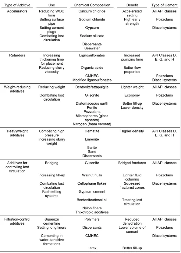
The properties of the cement to be used for oil well cementing must often be modified to meet the demands of the well application. The modification will be done by mixing other chemicals compounds called additives that will actively alter the hydration chemistry. An overview of the most commonly used cementing additives is given by the SPE Monograph Series, Cementing book as shown in Table 5 and 6 (Smith D. , 2003). The tables also include an indication of the primary uses and benefits along with the cements that they can be used with. The primary effects of the cement admixtures on the physical properties of the cement either as slurry or set are presented in Table 6 (Smith D. , 2003). Many chemicals have proved to be effective in modifying the properties of portland-cement slurries. When these additives were used alone, there will be primary effects to the cement slurry in which can be beneficial. Thus, it may affect the cement slurry performance properties. These effects can be enhanced or can be modified further by adding additional additives in the making of the cement slurry.
The knowledge of making an enhance portland cement slurry by adding additives can be applied to produce geopolymer cement. The question that will be raised is what are the additives that can be used together with MIRHA and fly ash to form geopolymer well cement for oil wells.
A research entitled Compressive Strength and Interfacial Transition Zone Characteristic of Geopolymer Concrete with Different In-Situ Curing Condition (Nuruddin, Kusbiantoro, Qazi, & Shafiq, 2011) has showed a few examples of geopolymer made of fly ash and MIRHA. The compositions of materials used in their experiments are as shown in Table 7 while the chemical composition of fly ash and MIRHA are shown in Table 8.
13
Table 5: Summary of oil well cementing additives
14
Table 6: Summary of oil well cementing additives (continued)
15 Mix
code
Fly ash (kg/m3)
MIRHA (kg/m3)
CA (kg/m3)
FA (kg/m3)
NaOH (kg/m3)
NaSiO2 (kg/m3)
Water (kg/m3)
Sugar (kg/m3)
A1 350 0 1200 645 41 103 35 10.5
A2 339.5 10.5 1200 645 41 103 35 10.5
A3 332.5 17.5 1200 645 41 103 35 10.5
A4 325.5 24.5 1200 645 41 103 35 10.5
B1 350 0 1200 645 41 103 35 10.5
B2 339.5 10.5 1200 645 41 103 35 10.5
B3 332.5 17.5 1200 645 41 103 35 10.5
B4 325.5 24.5 1200 645 41 103 35 10.5
C1 350 0 1200 645 41 103 35 10.5
C2 339.5 10.5 1200 645 41 103 35 10.5
C3 332.5 17.5 1200 645 41 103 35 10.5
C4 325.5 24.5 1200 645 41 103 35 10.5
Table 7: Mix proportions employed
16
Oxide MIRHA (%) Fly Ash (%)
SiO2 88.90 % 51.19 %
Al2O3 0.16 % 24.00 %
Fe2O3 0.45 % 6.60 %
CaO 0.63 % 5.57 %
MgO 0.72 % 2.40 %
SO3 0.32 % 0.88 %
K2O 3.65 % 1.14 %
Na2O - 2.12 %
Table 8: Fly ash and MIRHA chemical compositions
2.3 Compressive Strength
One of the main factors in determining cement to be used for oil wells is the compressive strength of the cement itself. By definition, compressive strength of a material is the value of uniaxial compressive stress reached when the materials fails completely. The compressive strength of a material can be determined by conducting compressive strength test. The compressive strength will be calculated from the failure load divided by the cross sectional area resisting the load and reported in units of pound-force per square inch (psi) or in its SI unit which is megapascals (MPa) (NRMCA, 2003).
Cylindrical specimens for the testing should be 6 inch x 12 inch or 4 inch x 8 inch when specified (NRMCA, 2003). The smaller specimen will be a lot easier to be produced and handle in lab. The diameter of the cylinder used should be at least 3 times the nominal minimum size of the coarse aggregate used in the concrete (NRMCA, 2003).
17
The recorded data of the specimen mass before testing also might be required for further usages. To provide a uniform load distribution during testing, the cylindrical specimen will be capped generally with sulfur mortar (ASTM C 617) or neoprene pad caps (ASTM C 1231). The cylindrical specimen’s diameter should be measured in two locations at right angles to each other at mid-height of the specimen. Then, the average value will be calculated to determine its cross sectional area. If the two measured diameters differs more than 2%, the specimen cannot be used for testing. The testing also required the specimen to be located at the center of the compression-testing machine to ensure the proportionally distributed load to the specimen and the machine should be maintained at 20-50 psi/s (0.15-0.35 MPa/s) during the latter of the loading phase (NRMCA, 2003). The type of break should be recorded and the common break pattern is a conical fracture as shown in Figure 1.
Upon completion of the compressive strength test for all specimens, the data have to be recorded. The results will be presented in able and graph as shown in Figure 2 (Nuruddin, Kusbiantoro, Qazi, & Shafiq, 2011).
18
Figure 1: Fractured Test Specimen at Failure
Figure 2: Example of compressive strength test results
19
CHAPTER 3 METHODOLOGY
3.1 Research Methodology
The methodology of the research is presented in the following flow chart. It explains the development of the research within the time given which are during FYP1 and FYP2. Thus this research will be executed as planned in manageable approach in term of time, cost and its feasibility.
Figure 3: Methodology Flow Chart
Finalizing the topic of FYP
First research on the topic (overall)
Selecting the scope of studies of the project
Detailed research on the research based on
scope of studies Developing various
models of geopolymer cement
Curing process of the models
Testing the models and record the results
Results interpretation and conclusion
20 3.2 Project Activities
The time given to complete the research is 8 months and steps as explained in the flow chart will be followed to ensure its successfulness. To enhance the flow of the research, the time frame will be divided into 3 phases which are Early Research Development, Middle Research Development, and Final Research Development.
Early research development basically is the studies of the conducted researches and projects. The main references will be technical papers, journals, and books to allow better understanding of the involved concept and theories that will be used to execute this project. Variables and methodology to be used in this research also will be determined in this phase.
For the middle research development, various models of geopolymer cement will be produced. The variety of the models is determined by its composition in which will affect its properties. Any improvisation to the models also will be done during this stage depending on the arising problems when developing the models.
In the final research development, the testing to the models produced will be conducted.
Compressive strength test will be conducted to all produced models by using compressive-testing machine available at the lab. The results of the testing will be recorded properly and will be presented. Documentation of the whole research also will be completed and it will be open for further improvement.
21 3.3 Key Milestone
Below are the key milestones that need to be achieved by the author throughout the period of the research which is approximately 26 weeks.
Milestone Week
Early Research Development
Research background
Scope of studies and Assumptions
Literature review
1 - 9
Middle Research Development
Detailed research
Developing the models
Models improvisation due to raises issue
10 - 21
Final Research
Testing the models
Results gathering
Completing the documentation
22 - 26
Table 9: Key milestones
3.4 Gantt Chart
The key milestones explained earlier are summarized in the Gantt chart in the Appendix I.
22 3.5 Experiment
In this research, 6 different geopolymer cement composition were prepared and tested by using properties of the existing well cement given by Table 3 as the benchmark. The geopolymer cement samples are cured at temperature of 80F for 24 hours. Figure 4 shows the flow chart of the experiment.
Figure 4: Flow chart of experiment
3.5.1 Slurry Preparation
The geopolymer is formed by adding silica rich materials with alkaline activator. In this research, the silica rich materials used are fly ash and MIRHA while the alkaline activator used are sodium hydroxide and sodium silicate. In preparing the slurry, the portion of the alkaline activator was made constant. Thus, the 6 different types of geoplymer cement slurries as mentioned earlier were made by altering the silica rich content proportions which are the fly ash and the MIRHA content. Fly ash was set to be the primary silica rich content and the MIRHA was set to be the secondary.
Cement slurries preparation
•6 types of cement slurries composition were prepared
Oven curing
•cement slurries were put into mold for temperature curing at 80F for 24 hours
Compressive strength determination
•the cured
geopolymer samples were tested for compressive strength using compressive strength testing machine
Geopolymer Silica Rich Materials
+
Alkaline ActivatorFly ash(primary) + MIRHA(secondary) NaOH + Sodium Silicate
Figure 5: Composition of geopolymer
23
Figure 7: Mixing process of slurry Figure 6: From left are sodium
hydroxide, sodium silicate, MIRHA and fly ash used for slurry design
Figure 6: Slurry is put into 50mm x 50mm mold
Figure 7: Molded slurry is put into oven for curing process
24
Table 10: Composition of cement slurries employed in this research
MIRHA was prepared as early as before the slurry preparation stage. Raw rice husk ash was put into microwave incinerator at 800C for 24hours before it can be used for slurry preparation. The alkaline activator to ash ratio used in this slurry design is 0.5:1 in which half volume of the alkaline activator to 1 volume of ash. As for the alkaline activator, the ratio of NaOH to sodium silicate used in this slurry design is 1:2.5 in which 1 volume of NaOH is to 2.5 volume of sodium silicate. The slurries in this research were prepared with the composition employed as shown in Table 10. Once the mixtures were ready, they were put into the constant mixer container to be mixed and become the slurries. The slurries were then put into 50mm x 50mm x 50mm cube mold.
Cement Slurry Sample Composition
Geo A 100% Fly ash + 12M NaOH + Sodium Silicate
Geo B 90% Fly ash + 10% MIRHA + 12M NaOH + Sodium Silicate
Geo C 80% Fly ash + 20% MIRHA + 12M NaOH + Sodium Silicate
Geo D 70% Fly ash + 30% MIRHA + 12M NaOH + Sodium Silicate
Geo E 60% Fly ash + 40% MIRHA + 12M NaOH + Sodium Silicate
Geo F 50% Fly ash + 50% MIRHA + 12M NaOH + Sodium Silicate
25 3.5.2 Oven Curing
Continuing previous step, the molded slurries were then put into the oven for curing process. As we are using Table 3 as the benchmark of our research, the curing process have followed the 80F curing temperature for 24 hours. The pressure used for this curing process is atmospheric pressure. All samples undergone the same curing procedure to ensure that it follows the standard and can be compared with existing oil well cement used in industries as Table 3 shows their properties.
3.5.3 Compressive Strength Test
This is the important part of the research where we determine the strength of all samples. After all samples undergone the curing process for 8 hours as stated previously, the samples have to be taken out of the oven and let it be at room temperature for a period of time before we proceed with the compressive strength testing. This is to ensure that the samples were all stable as drastic changes in temperature may affect its characteristics including its compressive strength. The compressive strength of the samples was determined by using 200KN Digital Compressive Strength Testing Machine.
26 3.6 Tools and Equipment
This research and experiment mostly conducted in civil laboratory of UTP as all of the tools and equipment are available at the same place. Required materials are listed in Table 11.
No. Materials
1 Rice husk ash
2 Fly ash
3 Sodium Silicate
4 NaOH
Table 11: Required materials for cement slurry design
Table 12 below shows the tools and equipment used in this research.
No. Equipment
1 Microwave Incinerator
2 Seaving machine
3 Constant mixer
4 50mm x 50mm x 50mm cube mold
5 Curing oven
Table 12: Tools and equipment used
27
CHAPTER 4
RESULTS AND DISCUSSION
This chapter will discuss the obtained result from the experiment conducted since the beginning of this research until current time.
4.1 Compressive Strength test
The obtained results are presented in Table 13 below.
Curing temperature: 80F Curing time: 24 hours Benchmark:
1) Typical compressive strength of oil well cement API class G cured at 80F, 24 hours = 1185 psi
2) Typical compressive strength of oil well cement API class H cured at 80F, 24 hours = 1065 psi
Geopolymer samples
Compressive Strength (psi) Average
compressive strength (psi)
1 2 3
A 1435.87 1493.89 1450.38 1460.05
B 2079.84 2045.03 2132.05 2085.64
C 1575.11 1485.19 1512.74 1524.35
D 1389.46 1464.88 1448.93 1434.42
E 1015.26 870.23 942.75 942.75
F 899.23 841.23 942.75 894.88
Table 13: Compressive strength results
28
From the results, the compressive strength is increase from sample A to sample B in which sample A is 100% fly ash while sample B is 90% fly ash and 10% MIRHA.
However, the strength begins to decrease from sample B to sample F in which the portion of fly ash being reduced by 10% and portion of MIRHA being increased from sample A to sample F. In other words, when the portion of fly ash being reduced more than 10% and the portion of MIRHA being increased more than that of sample B, the compressive strength will be reduced. The maximum average compressive strength obtained from the experiments is 2085.64 psi by sample B and the minimum average compressive strength obtained is 894.88 psi by sample F.
It is certain that additional of MIRHA to the slurry design give an impact to the improvement of the compressive strength when sample B was tested. However the compressive strength obtained when the portion of MIRHA was being increased more than 10% is decreasing. From this, we can say that additional of MIRHA in the geopolymer design to improve its compressive strength has its limit. In order to show a clearer comparison between samples, the results are presented in bar chart below.
1185.00
1065.00
1460.05
2085.64
1524.35
1434.42
942.75 894.88
0.00 500.00 1000.00 1500.00 2000.00 2500.00
Class G Class H Sample A Sample B Sample C Sample D Sample E Sample F
Average Compressive Strength (psi)
Cement Type
Figure 10: Compressive strength comparison
29
From the bar chart in Figure 10, it is obvious that the geopolymer sample A, B, C and D are better than the benchmarks which are API cement classes G and H in terms of compressive strength. The greatest average compressive strength obtained is 2085.64 psi by geopolymer model B is almost double the compressive strength of the API cement classes G and H. Figure 11 and 12 shows the compressive strength improvement in percentage, as compared to API cement classes G and H respectively.
23.26
76.01
28.64
21.01
0 10 20 30 40 50 60 70 80
Sample A Sample B Sample C Sample D
Percentage improvement compared to API cement class G(%)
Cement Type
Figure 11: Compressive strength improvement compared to API cement class G
30
As mentioned earlier in this paper (Table 1), API cement classes G and H are most widely used as basic oil well cement from surface to 8000ft of depth. By introducing MIRHA as a material to produce a geopolymer for oil cementing purpose, we can actually achieve far better strength than that of conventional API cement classes G and H. From Figure 11 and 12; it is clearly showed that the geopolymer samples by using MIRHA have improved the compressive strength. From this result, we can suggest that MIRHA geopolymer cement can be used as oil well cement with better strength to replace API cement classes G and H in the oil and gas industry.
37.19
95.91
43.19
34.74
0 20 40 60 80 100 120
Sample A Sample B Sample C Sample D
Percentage improvement compared to API cement class H(%)
Cement Type
Figure 12: Compressive strength improvement compared to API cement class H
31
CHAPTER 5
CONCLUSION AND RECOMMENDATION
From this research, we found out that:
1. Geopolymer using MIRHA and fly ash have produced a competitive results in terms of compressive strength compared to conventional API cement classes to be used as oil well cement.
2. Increasing portion of MIRHA while reducing the portion of fly ash have produced greater strength until 90% of fly ash and 10% of MIRHA are being used in slurry design and the strength will be reduced if more than 10% MIRHA is being used for 24hours curing time at 80F.
3. Maximum average compressive strength obtained is 2085.64 psi by geopolymer sample B.
4. Minimum average compressive strength obtained is 894.88 psi by geopolymer sample F.
5. Of all geopolymer samples made, samples A, B, C, and D have shown great improvement compared to API cement classes G and H, with sample B is the greatest improvement followed by sample C, sample A and sample D.
6. In comparison with API cement class G, the greatest improvement of compressive strength is shown by sample B with 76.01% of improvement.
7. In comparison with API cement class H, the greatest improvement of compressive strength is shown sample B with 95.91% of improvement.
8. Sample B can be said have double the compressive strength compared to that of sample H.
9. From the experiment, it can be concluded that sample A, B, C and D have achieved better compressive strength than API cement classes G and H and thus can replace API cement classes G and H in its oil well cementing application as basic cement used in which from the surface to 8000ft of depth.
32
Background researches regarding geopolymer cement by using MIRHA, slurry preparation and compressive strength has given a better understanding on the topics, thus a better geopolymer cement using MIRHA for oil well cementing have been produced.
At the end of this research, all of the objectives of this research which are: (1) geopolymer cement using MIRHA (2) improved strength of oil well cementing system (3) a green technology of well cementing system (4) make use of the fly ash and rice husk ash produced in industries were all successfully achieved.
Nevertheless, what have been done might not be the best. There will always be a room for improvisation. Therefore, listed below are the recommendations for future works.
Recommendations for future works:
1) Slurry design with different proportions of fly ash, MIRHA, sodium silicate, and sodium hydroxide than being used in this research can be done to find the best geopolymer slurry design.
2) Different molarity of sodium hydroxide solution can be used to find the best outcome.
3) Longer curing time of the same geopolymer design used in this research can be done to study the behavior and properties of the produced geopolymer in longer period of time.
4) High pressure high temperature (HPHT) curing method can be done to simulate the high temperature and high temperature for oil well cement in greater depth and thus the results can be compared with other API cement classes.
33 REFERENCES
A.Brandl, W. D. (2010). Technically and Economically Improved Cementing System With Sustainable Components. IADC/SPE Asia Pacific Drilling Technology Conference and Exhibition.
Ho Chi Minth, Vietnam: SPE & IADC.
Arina binti Sauki, S. I. Effects of Pressure and Temperature on CO2 . International Journal of Engineering & Technology IJET-IJENS Vol: 10 No: 04.
ASTM C 1231. In Annual Book of ASTM Standards. (Vol. 4). ASTM.
ASTM C 617. In Annual Book of ASTM Standards. (Vol. 4). ASTM.
Crook, R. (2006). Petroleum Engineering Handbook Vol. 2 - Drilling Engineering. (R. F. MItchell, Ed.) Society of Petroleum Engineers.
D.G. Calvert, D. K. (1990). API Oilwell Cementing Practices. Journal of Petroleum Technology.
Mohd, W. A. (2011). Geopolymer Cement for Oil Well With Improved Properties.
NRMCA. (2003). CIP35 - Testing Compressive Strength of concrete. Concrete in Practice: What, Why and How?
Nuruddin, M. F., Kusbiantoro, A., Qazi, S., & Shafiq, N. (2011). Compressive Strength and Interfacial Transition Zone Characteristic of Geopolymer Concrete With Different In-Situ Curing Condition.
Polkowski, G. (1987). Correlation of Oilwell Cement Performance With Cement Characteristics.
SPE 16651.
Smith, D. (1990). Cementing; SPE Monograph Series, vol. 4. Society of Petroleum Engineers.
Smith, D. (2003). Cementing, SPE Monograph Series. Society of Petroleum Engineers.
Smith, R. Internal AmocoReport on Cementing.
34 APPENDIX 1
Research Gantt Chart.
Phase
FYP 1 FYP 2
Weeks
1 2 3 4 5 6 7 8 9 10 11 12 13 14 15 16 17 18 19 20 21 22 23 24 25 26 Early Research Development
Background research Determining scope of studies Literature reviews
Middle Research Development Detailed research Developing geopolymer models Models improvisation Final Research Development
Testing of models
Results gathering Completing documentation