A project dissertation submitted to the Universiti Teknologi PETRONAS Civil Engineering Program in partial fulfillment of the requirement for the BACHELOR OF ENGINEERING (Hons.). This is to certify that I am responsible for the work presented in this project, that the original work is my own, except as specified in the references and acknowledgments, and that the original work contained herein was not undertaken or done by unspecified sources or persons . Nitrogen and organic matter removal using a single integrated reactor consisting of aerobic and anoxic zones has been a common focus in this investigation.
The aim of this study was to develop a new integrated sequential anoxic-aerobic (ISA) reactor for the removal of organic matter and nutrients and to evaluate the efficiency in terms of organic matter and nitrogen removal according to different reactor configurations. Alhamdulillah, my praise to the Almighty for his blessings to give me the opportunity to complete my senior year. I would like to express my utmost gratitude and thanks to the people who directly or indirectly participated in the completion of this FYP project.
Also to the technicians in the environmental laboratory, Mr. Anuar, Mr. Zaaba and Ms. Yusmarina for their support and help in carrying out all the relevant experiments in the laboratory. And last but not least to my family and friends for their constant support.
Background of Study
Basically, nitrogen removal can be classified into three main types of processes that include physical, chemical and biological processes (Halling-Sorensen & Jorgensen, 1993). This is due to the fact that this method is relatively effective and economical (Carrera et al., 2003) but not for industrial wastewater with high strength since the nitrification process can be hindered by the high concentration of ammonium or nitrite (Anthonisen et al. , 1976). The conventional biological method of nitrogen removal follows the two-step process of nitrification through autotrophic oxidation which converts ammonia to nitrite and then to nitrate.
While denitrification through heterotrophic reduction, which reduces nitrate to nitrogen gas (Ding et al., 2013; Yao et al., 2013). The processes of nitrification and denitrification will occur in two separate independent units of aerobic and anoxic reactors respectively. The conventional processes used in various domestic wastewater treatment plants are currently unable to meet the recent amendment to the Environmental Quality Regulations (Sewerage) 2009, as nitrification is inhibited due to insufficient solids retention time (SRT) and the sludge age of the biomass (Kutty, et al., 2011).
According to Rafael et al. 2012), for carbon and nitrogen removal, the conventional treatment system “needs three treatment units, which increases the construction costs of the treatment system” (p. 163).
Problem Statement
Objectives
- Wastewater Treatment
- Organic Matter Removal
- Nitrification and Denitrification
- Past Studies
The treatment usually involves a two-stage process, nitrification and denitrification, which will take place in two separate reactors (Moura et al., 2012). The research is further improved by An et al. 2013), produced a new Integrated Vertical Membrane Bioreactor (IVMBR). Aeration costs can also increase due to achieving hydrodynamic scrubbing effect to remove any blockage at the membrane by pumping lots of air into the reactor (Yao, et al., 2013).
Although Ding et al. (2011) shows good results in terms of removal efficiency, but the use of a sophisticated intelligent control system increases the capital cost of the reactors. In another study by Yao et al. (2013), used heterotrophic nitrifying-aerobic denitrifying bacteria in their reactor. As for the studies by Du et al. 2014) used anaerobic ammonium oxidation bacteria (Anammox) inside a sequential batch reactor.
The study by Yao et al., (2013) using aerobic denitrifying bacteria in the reactor gives them the advantage as the denitrifying bacteria will not be suppressed due to oxygen tolerance. From the recent study by Du et al. 2014) Anammox was also observed to be inhibited under high organic matter which resulted in decreased TN removal efficiency.
- Reactor Configuration
- Synthetic Wastewater
- Reactor Operation and Monitoring
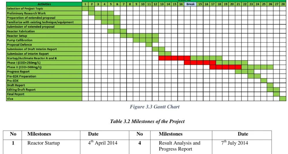
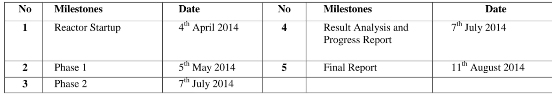
- Project Milestone/Gantt Chart
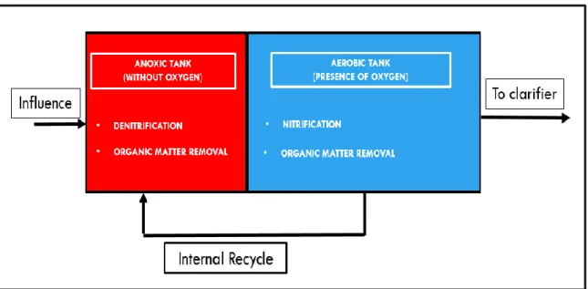
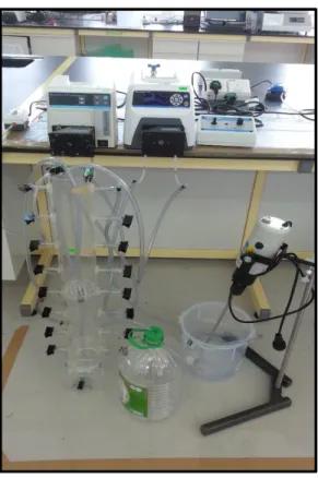
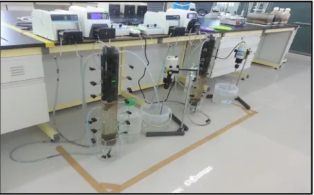
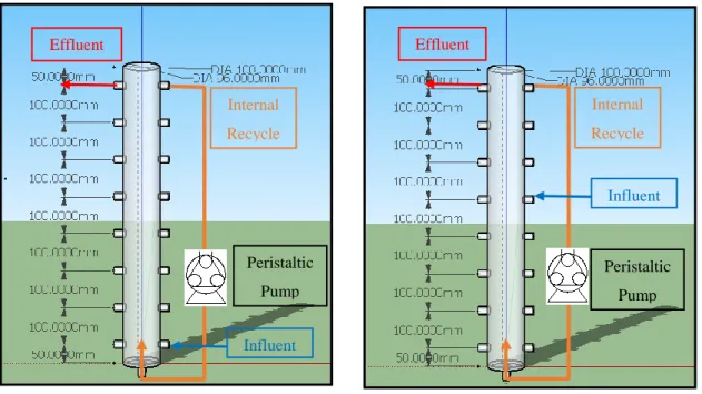
In Reactor A, the influence inlet is set to the anoxic zone (Fig. 3.2a), while Reactor B is located in the aerobic zone of the reactor (Fig. 3.2b) with the same flow rate of 5 liters/day. The upper outlet of the reactor are both connected to the lower one to create internal recycling of nitrification to the lower outlet for a denitrification process at a flow rate of 15 liters/day. The remaining outputs are used to collect samples at regular intervals for parameter monitoring.
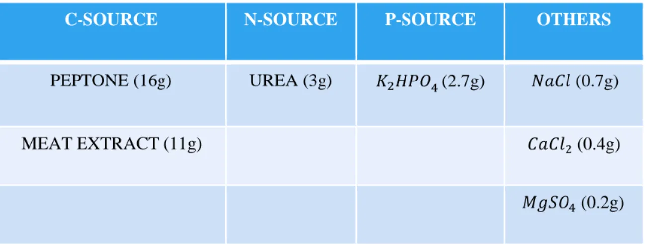
Organization for Economic Co-operation and Development (OECD) synthetic wastewater is used for the reactor. The stock solution will be appropriately diluted and fed to the reactor for treatment evaluation. The reactor is operated under continuous aeration with HRT for 24 hours to promote nitrifying aerobic microorganisms.
The influent flow rate was set at 5L/day with internal recycling rate of 3Q of the influent rate (15L/day) with SRT of 25 days. All monitoring will be in accordance with the American Public Health Association (APHA) 2005, Standard Methods for the Examination of Water and Wastewater. Since the scope of the study does not include clarifier, a high value of COD in effluent is expected by the microorganism that is effluent during sample collection.
This parameter will therefore be observed every day to ensure sufficient DO supply of 2mg/L at the aerobic zone. The MLSS will also be monitored once every two weeks to be around the design value of 2200mg/L. This is to ensure enough micro-organisms inside the reactor and not be completely washed out or experience endogenous respiration.
It is removed by conversion to nitrogen gas, which bubbles up to the top of the reactor and diffuses into the atmosphere. As for phosphorus, the concentration is expected to be consistent throughout the experiment due to the fact that the reactor is designed primarily for nitrogen removal. The removal efficiency and organic loading rate for both reactors will be evaluated during the studies.
Reactor Fabrication and Setting up
In reactor A, the inlet was set to the aerobic zone (Figure 3.2a), while reactor B was set to the anoxic zone of the reactor (Figure 3.2b). The influent flow rate is set at 5 L/day with an internal influent recycle rate of 15 L/day.
Reactor Startup
The pumps are calibrated to ensure that the reactors are accurately hydraulically loaded on a daily basis. The acclimatization period started on May 20, 2014 with aerobic and anoxic sludge from the Universiti Teknologi PETRONAS Sewage Treatment Plant (UTP's STP). Initially, the aerobic sludge was placed in another container with bioballs to promote growth with a constant supply of oxygen and substrate.
While anoxic sludge was immediately poured into the reactor and the influent and effluent soluble COD concentration was monitored to ensure the presence of the bacteria. After three days, the NOB bioballs are set up in the reactor and the complete reactor operation. During the first day of the start-up period, a more dilute influent was supplied to the reactors to ensure that most of the uncontrolled variable taken from UTP's STP was consumed.
A high removal efficiency was noted after seven days for both reactors due to the effective acclimatization of biomass to the reactors.
Performance Monitoring
- Organic Substance Removal
- Ammonia-Nitrogen Removal
- Nitrate-Nitrogen Removal
- Phosphorus Removal
- Formulation of Kinetics
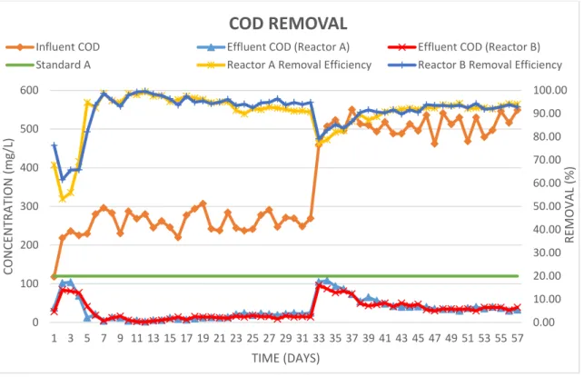
Interestingly, both Reactor A and Reactor B have the highest removal efficiency of 94.34% on the 50th and 52nd day, respectively. The experimental results of ammonia and nitrogen removal are recorded and shown in Figure 4.5 for both phase 1 and phase 2. During phase 1, the average ammonia-nitrogen feed to both reactor A and reactor B averages 18.89 mg/l .
During the period of the first 14 days in phase 1, the value of ammonia-nitrogen fluctuates strongly. This produces an influent average ammonia-nitrogen concentration of 9.46 mg/L, simulating the composition of low-strength untreated domestic wastewater characteristics adopted by Metcalf and Eddy, (2013). On the other hand, the average ammonia-nitrogen used for both reactor A and reactor B in phase 2 was 24.3 mg/L.
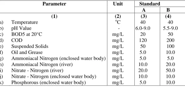
Thus, the system was provided with excess alkalinity of 120 mg/L to compensate for the lack of alkalinity needed to oxidize the 8.5 mg/L ammonia-nitrogen in the system. The result shows a slight decrease in ammonia-nitrogen in the system after adding alkalinity. As shown in Figure 4.7, the effluent ammonia concentration in reactor A was within the standard limit A when the DO concentration was constantly maintained above 2.0 mg/L.
It can be seen in Figure 4.9 and Figure 4.10 both reactors experience DO above 2 mg/L at several points, even during the steady state (Reactor A: Day Reactor B: Day 40, 54), but the discharge does not fluctuate as much as experience through ammonia removal. From Figure 4.11, the average removal for both reactors was around 25-30% indicating the existence of biomass in the system. In the anoxic zone, the kinetics substrate removal rate of Reactor B is observed to be 0.0035 while Reactor A indicates 0.0029.
At aerobic zone, Reactor B basically has a higher substrate removal rate during phase 1, but lower substrate removal rate in phase 2 compared to Reactor A due to the kinetics gradient. From the Figure 4.13, the kinetics of substrate removal rate for Reactor A and Reactor B were 0.006 and 0.0057 respectively. Although the kinetics of substrate removal is low, it still shows the presence of nitrification process in the system.
Conclusions
Recommendations
This indicates that the ISA reactor is fully operational and able to treat the wastewater by reducing the respective substrate. Condition combined with step-feed mode for nitrogen removal in granular sequencing batch reactors (GSBRs). Ammonia-Nitrogen and Nitrate Removal with Modified Conventional Activated Sludge System to Meet New D.O.E Regulations.
The sequence batch reactor as a powerful tool for the study of slow-growing anaerobic ammonium-oxidizing microorganisms. Simultaneous removal of organic matter and nitrogen by heterotrophic nitrifying-aerobic denitrifying bacterial strain in a membrane bioreactor. Nitrogen removal from synthetic wastewater by simultaneous nitrification and denitrification (SND) via nitrites in an intermittently aerated reactor.