Mobile Application for Augmented Reality Animal Dissection
By
Edwin Lee En Yueng
A REPORT SUBMITTED TO
Universiti Tunku Abdul Rahman in partial fulfillment of the requirements
for the degree of
BACHELOR OF INFORMATION TECHNOLOGY (HONS) COMPUTER SCIENCE
Faculty of Information and Communication Technology (Kampar Campus)
MAY 2019
UNIVERSITI TUNKU ABDUL RAHMAN
REPORT STATUS DECLARATION FORM
Title: __________________________________________________________
__________________________________________________________
__________________________________________________________
Academic Session:
I __________________________________________________________
(CAPITAL LETTER)
declare that I allow this Final Year Project Report to be kept in
Universiti Tunku Abdul Rahman Library subject to the regulations as follows:
1. The dissertation is a property of the Library.
2. The Library is allowed to make copies of this dissertation for academic purposes.
Verified by,
_________________________ _________________________
(Author’s signature) (Supervisor’s signature) Address:
_________________________
Supervisor’s name
Date: Date: ____________________
Mobile Application for Augmented Reality Animal Dissection
By
Edwin Lee En Yueng
A REPORT SUBMITTED TO
Universiti Tunku Abdul Rahman in partial fulfillment of the requirements
for the degree of
BACHELOR OF INFORMATION TECHNOLOGY (HONS) COMPUTER SCIENCE
Faculty of Information and Communication Technology (Kampar Campus)
MAY 2019
DECLARATION OF ORIGINALITY
I declare that this report entitled “
Mobile Application for Augmented Reality Animal Dissection
” is my own work except as cited in the references. The report has not been accepted for any degree and is not being submitted concurrently in candidature for any degree or other award.Signature : _________________________
Name : ________
Date : __________________
ACKNOWLEDGEMENTS
Foremost, I would like to express my sincere gratitude to my advisor Mr. Tou Jing Yi for his guidance, motivations, suggestions and advices in the completion of my final year project.
I would also like to express my gratitude to my family for their support in my studies whether morally, financially or physically. Without their support, the completion of this project would not have been possible.
I would also like to thank all my friends and lecturers who have directly or indirectly helped me in this project.
ABSTRACT
For decades of years, animal dissection has been used as an educational tool for educators to teach anatomy. Educators find it difficult to find alternatives that is on par with traditional dissection. However, traditional animal dissection requires a lot of preparation for a single session of dissection. It is inefficient and not cost effective as an educational method. Educators feel that alternatives could not provide the same experience that actual dissection provides such as the quality of empathy and appreciation. This project aims to provide an alternative that could fulfil these requirements by developing a mobile application that utilizes augmented reality technology. It aims to provide a virtual dissection environment with virtual dissection tools through the use of gestures so that users could gain an insight into how dissection is done. The application will provide a multiplayer platform that can be used to assist educators in teaching dissection in a classroom environment which will help in coordinating multiple students.
TABLE OF CONTENTS
LIST OF TABLES ... vi
LIST OF FIGURES ... vii
LIST OF ABBREVIATIONS ... x
CHAPTER 1 : INTRODUCTION ... 1
1.1BACKGROUND ... 1
1.2PROBLEM STATEMENT AND MOTIVATION ... 3
1.2.1 Problem Statement ... 3
1.2.2 Motivation ... 3
1.3OBJECTIVES ... 4
1.4PROJECT SCOPE ... 4
1.5PROPOSED APPROACH ... 5
CHAPTER 2 : LITERATURE REVIEW ... 7
2.1ADEBATE ON DISSECTION AND ALTERNATIVES ... 7
2.2ATTITUDE TOWARDS DISSECTION... 8
2.3VIRTUAL REALITY TRAINING IN NEUROSURGERY ... 11
2.4DISSECTION LAB MOBILE APPLICATION REVIEW ... 14
2.5FROGGIPEDIA IOSAPPLICATION REVIEW ... 16
CHAPTER 3 : METHODOLOGY... 19
3.1SOFTWARE DEVELOPMENT METHODOLOGY ... 19
3.2TOOLS USED ... 21
3.3SYSTEM DESIGN ... 22
3.3.1 System Overview ... 22
3.3.2 Module Descriptions ... 23
3.4USER INTERFACE DESIGN ... 31
3.5IMPLEMENTATIONS ... 34
3.5.1 Software Environment ... 34
3.5.2 Pre-Implementation Processes ... 34
3.5.3 Implementation of Modules ... 36
CHAPTER 4 : DISCUSSIONS AND VERIFICATION ... 45
4.1DISCUSSION ON IMPLEMENTATION TECHNIQUES ... 45
4.1.1 Scalpel interactions ... 45
4.1.2 Modelling of the dissected skin flaps... 46
4.1.3 Forceps and bones interactions ... 47
4.2SYSTEM VERIFICATION TEST PLAN ... 48
4.2.1 Unit Testing ... 48
4.2.2 Integration Testing ... 50
4.2.3 System Testing ... 50
4.3IMPLEMENTATION ISSUES AND CHALLENGES ... 51
CHAPTER 5 : CONCLUSION... 52
5.1PROJECT REVIEW ... 52
5.2FUTURE IMPLEMENTATIONS ... 53
CHAPTER 6 BIBLIOGRAPHY ... 54
LIST OF TABLES
Table 2-1 Shows percentage of educators who agreed or disagreed with the following statements regarding the use of dissection and dissection alternatives
(Osenkowski et al. 2015:p341). ... 9 Table 2-2 Shows percentage of students who agreed or disagreed with the following
statements regarding the use of dissection and dissection alternatives
(Osenkowski et al. 2015:p344). ... 10 Table 3-1 Project work breakdown structure table ... 20
LIST OF FIGURES
Figure 1-1 Propose System Flowchart ... 5
Figure 2-1 Shows prevalence of animals commonly used as dissection specimens in precollege biology education (Osenkowski et al. 2015:p342). ... 10
Figure 2-2 Shows a user selected a cutting plane of a mannequin head with the props interface showing the corresponding MRI image cuts part of preoperative surgical planning. (Alaraj et al. 2011). ... 11
Figure 2-3 Showing the ImmersiveTouch™ system in operation. (Alaraj et al. 2011). ... 12
Figure 2-4 Promotional image of Dissection Lab from Navtek Solutions website ... 14
Figure 2-5 Main screen of Dissection Lab ... 14
Figure 2-6 Learn about species screen (Left) and dissection process (right) ... 15
Figure 2-7 External anatomy screen ... 15
Figure 2-8 Life cycle screen ... 16
Figure 2-9 AR anatomy screen ... 16
Figure 2-10 Muscular system of the frog in the AR anatomy screen ... 17
Figure 2-11 Muscular system of the frog in the AR anatomy screen ... 17
Figure 2-12 Dissection screen ... 18
Figure 2-13 Organs identification ... 18
Figure 3-1 Incremental Development Model ... 19
Figure 3-2 System Flowchart ... 22
Figure 3-3 Augmented Reality Module ... 23
Figure 3-4 Scalpel Tool Module ... 23
Figure 3-5 Illustration of a cut line on a 2D polygon ... 24
Figure 3-6 Front view of 3D model (left) and angled view of 3D model (right) ... 24
Figure 3-7 Drawn line on mesh with nearest vertices selected ... 25
Figure 3-8 Points formed from drawn line on mesh with nearest vertices selected .... 25
Figure 3-9 Forceps tool module flowchart... 26
Figure 3-10 Frog skin flap dragged at touch point (white dot) ... 26
Figure 3-11 Mouse pointing direction (dotted line) to touch point (white dot) ... 27
Figure 3-12 Pin Tool Module Flowchart ... 28
Figure 3-13 Host Migration Architecture ... 28
Figure 3-14 Multiplayer System Module Flowchart ... 29
Figure 3-15 Gestures Flowcharts ... 30
Figure 3-16 Main screen with “Start Dissection button” and “Multiplayer” button ... 31
Figure 3-17 Dissection screen ... 31
Figure 3-18 Multiplayer lobby screen ... 32
Figure 3-19 Create room popup ... 32
Figure 3-20 Waiting screen - Instructor view ... 33
Figure 3-21 Waiting screen – Student view ... 33
Figure 3-22 A cavity with 2 skin flaps in a 3D model of a frog ... 34
Figure 3-23 Simple bone rig for the skin flaps ... 35
Figure 3-24 Bones weight relation with mesh (top view)... 35
Figure 3-25 Mock up 3D models of the organs of a frog ... 36
Figure 3-26 Image target created in Vuforia Developer Portal ... 37
Figure 3-27 Unity scene with AR camera and image target with 3D frog model ... 37
Figure 3-28 Selection of vertices flowchart ... 38
Figure 3-29 Casting a ray from mouse screen point to 3D mesh ... 38
Figure 3-30 Checking selected vertex in VertexLibrary flowchart ... 39
Figure 3-31 Create New Application page on Photon Cloud ... 41
Figure 3-32 Photon Server Settings in Unity’s inspector ... 41
Figure 3-33 Network object diagram ... 42
Figure 3-34 Photon View component applied to the left skin flap of the frog ... 43
Figure 3-35 Gestures Handling module implementation flowchart ... 44
Figure 4-1 Colliders on cut lines ... 45
Figure 4-2 Skin flap of the 3D frog model with a single bone and filled rim ... 46
Figure 4-3 Thin skip flap with multiple bones assigned ... 46
Figure 4-4 Inverse kinematics bones system in Unity ... 47
Figure 4-5 Testing of Vuforia’s target detection ... 48
Figure 4-6 Selected vertices on mesh and the list of selected vertices ... 48
Figure 4-7 Mouse picking up the frog liver using the forceps tool ... 49
Figure 4-8 Sample touch gesture debug log ... 49
Figure 4-9 Picking up an organ with pinch gestures (shown as 2 circles) while in augmented reality environment on an Android device ... 50
Figure 4-10 Creases formed due to pre-defined cut lines (left) and deformity of thin skin flaps (right) ... 51 Figure 5-1 Mesh cutting implemented in Unity ... 53
LIST OF ABBREVIATIONS
3D 3-Dimension
AR Augmented Reality
CT Computed Tomography
IDE Integrated Development Environment IK Inverse Kinematics
LAN Local Area Network
MRI Magnetic Resonance Images
OR Operating Room
PUN Photon Unity Networking SDK Software Development Kit SQL Structured Query Language VR Virtual Reality
Chapter 1: Introduction
CHAPTER 1 : INTRODUCTION
1.1 Background
The teaching and practice of animal dissections are deeply rooted in the study of human anatomy and physiology. In order to learn more about how our bodies work, we have turned to the use of animal dissections as an alternative to learn how a complex living organism such as humans function. This practice have continued on to the modern day as a part of our educational system and has been considered to be one of the most effective method to learn about anatomies but has also raised many controversies.
Every year, millions of frogs and mice have been used as subjects of dissections for biological studies in class room environment whether in middle school, secondary or even college level. This practice have been thought of as a form of animal abuse from animal lovers and some students also find it uncomforting to dissect an animal.
Even though dissections may have exponentially increase our understanding of the anatomies of living creatures, some has said that it is at the cost of our humanity.
Furthermore, to prepare the subjects such as mice and frogs for dissection in a classroom environment requires a huge amount of effort. This includes the process of acquiring the animals, putting it into sleep and the discarding it after the dissection.
From this, it is obvious that it would have cost much time and generate a lot of waste just to conduct a single session of dissection. Besides that, the use of formalin to preserve the specimens might pose serious health issues to teachers and students who are constantly facing these chemicals. This is one of the concerns of educators who conducts dissection often.
Another problem that is faced by educator is that some students find that dissection is unethical and they find that rights should be given to students who do not wish to participate in the dissection. Nevertheless, this does not mean that students should opt out of studying anatomies entirely. Educators have always tried to provide a way to teach effectively to this group of students without compromising their learning experience. Forcing students to participate is definitely not an option as it will only create negative feelings towards biological studies. On the other hand, there is a lack of
Chapter 1: Introduction
effective alternatives that could provide the same pedagogical value compared to traditional dissection.
Alternatives has always been viewed as lesser in pedagogical value as most alternative that are available lacks realism and information that can be gain through real dissections. Nonetheless, this is mainly because most alternatives that are available are outdated and was never developed with the full potential of the technology that is currently available. The main problem with alternative has always been the lack of interaction and sensation that traditional dissection allows users to experience.
Therefore, a bias towards traditional dissection can be seen through various studies conducted regarding the use of alternative and traditional dissection as the main teaching method.
Undeniably, learning about anatomies through dissection has certainly played a huge role in the advancement of the biological field. Therefore, this project’s aim is to solve these problems. The solution revolves around the use of the augmented reality technology and the availability of smart phones everywhere. Instead of using living breathing organisms, this project aims to create a mobile application that will produce a virtual environment for everyone to be able to experience the process of dissection and anatomies without physically doing it.
Hence, the need of preparation for living animals and the inhumane act of sacrificing animals for our own knowledge gain can be reduced or even eliminated completely if this application is used in every classroom. Furthermore, it will even reduce the learning curve of biological studies as everyone will be able to gain access to dissections where ever they are and at any time that is convenient. With this project, it is hoped that the alternative proposed by this project can change the biasness towards traditional dissection.
Chapter 1: Introduction
1.2 Problem Statement and Motivation
1.2.1 Problem Statement
Educational instructors and teachers who have conducted animal dissections are unable to find an alternative that is on par with actual dissections and the process of preserving specimens for dissection is hazardous if exposed to it frequently. There are many applications that act as an alternative but it does not satisfy the needs of those who uses dissection as a learning tool. Some applications and textbooks are very informative but it does not provide the same realism and experience of performing a dissection. There are existing applications out there that allow users to perform dissection but it still does not meet the expectations of those who has a high regard for dissection. Therefore, most instructors tend to rely on traditional dissection as the main educational tool.
Lack of realism in existing alternatives
o Alternatives do not provide realistic interactions of real dissections in terms of handling dissection tools and the environment that are illustrated in applications tend to be bland and unrealistic.
Applications do not provide functionalities for group interactivity
o Existing applications do not provide functionalities that can be used to interact as a group such as having multiple users dissecting on the same specimen.
Applications do not provide the tools needed for educators to direct students o Existing applications are generally catered to solo usage which makes it
difficult for educators to give directions to their students during dissection sessions.
1.2.2 Motivation
There are many applications and alternatives that are very informative in anatomies however it does not meet the requirements that educators need to use as an alternatives as an educational tool in dissection. This project aimed to develop an application as an alternative to dissection that will be able to serve the needs of educators that uses dissections as an educational tool.
Chapter 1: Introduction
1.3 Objectives
1. To develop a mobile application that simulates virtual dissection through marker based augmented reality.
2. To develop a mobile application for virtual dissection with dissection tools that utilizes touch gestures.
3. To develop a mobile application that provides a platform for multiplayer dissection environment through the internet.
1.4 Project Scope
The scope of the project will be to develop a mobile application for virtual dissection. There are existing applications that provide similar functions however improvements will be made to serve the need of educators.
Marker based augmented reality of dissection environment
o The dissection environment will be augmented with the real environment of users by using the camera to track an image that will be used as the marker to determine where the virtual objects will be placed on the scene.
Virtual dissection tools that utilizes touch gestures
o Three types of tools will be provided to perform the dissection which is a scalpel, pin, and forceps.
o Gestures can be used to activate the tools without selecting the tools o The forceps can pick up virtual object with the pinch gesture.
o The scalpel executes the cut function through the gesture of drawing a line on targeted areas.
o The long press gesture activates the pin function.
Multiplayer system
o Users will be able to create a room that will be broadcasted on the internet.
o Other users can create new room or join the rooms available.
o The interactions on the virtual content will be synced with other users.
Chapter 1: Introduction
1.5 Proposed Approach
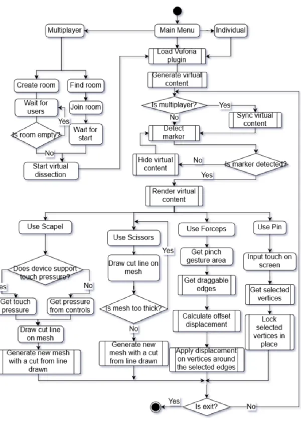
Figure 1-1 Propose System Flowchart
Chapter 1: Introduction
The proposed approach is made up of 6 modules that are integrated into one system. The modules are identified as the augmented reality module, scalpel tool module, scissors module, forceps tool module, pin module, and multiplayer system module. Each of this module will be integrated together to form a mobile application.
Augmented Reality Module
The augmented reality module works by first loading the Vuforia plugin which contains the libraries needed to perform image recognition to detect the marker and generating the virtual content and augment it onto the detected marker.
Scalpel Module
The scalpel module is activated when the user selects the scalpel tool. The tool is used to cut the 3D virtual specimen. The harder a user press on the screen the deeper the scalpel cuts.
Scissors Module
The scissors module is similar to the scalpel module. However, touch pressure is not taken into consideration as the tool will be able to cut through a single layer of mesh with a thickness that is lesser than or equal to a pre-defined thickness limit.
Forceps Module
The forceps module works by detecting the area afected by the pinch gesture. If there are edges in the selected area, the edges will be checked whether it is draggable.
Pin Module
The pin module is a simple tool that locks vertices in place so that part of the 3D virtual specimen can be hold in placed. The tool works by receiving touch input from user and the touch position will be used to determine an area of selected vertices.
Multiplayer System Module
The multiplayer system uses the host migration concept to connect multiple users in the virtual environment. However, instead of having a centralized server, the user that created (hosted) the room will be the server which will also be known as Master Client in the Unity’s Photon plugin.
Chapter 2: Literature Review
CHAPTER 2 : LITERATURE REVIEW
2.1 A Debate on Dissection and Alternatives
According to a survey done by Oakley (2012), it is shown that most of the teachers who have participated in the survey found that traditional dissection has unparalleled value compared to other substitutes. It was shown that “87.5% either agreed or strongly agreed with the statement, “Real animal dissection is important to the teaching of biology” and more than half (56.3%) agreed or strongly agreed that there are no substitutes for real animal dissection.” (Oakley 2012). From the statement, it was clear that traditional dissection has played an important role in the biological studies. However, does this mean that a better alternative should not be considered?
Even though most teachers who participated in the survey prefers traditional dissections, some have also expressed concerns mostly regarding health and safety.
Some of the concerns involves accidents from handling scalpels, pins and chemicals that might hurt the students, misbehaving students and classroom management issues.
Prolong exposure to formalin solution is also one of the main concern as it could cause health issues. (Oakley 2012).
From the survey done by Oakley (2012), there were 125 participants who reported using alternatives out of the 153 teacher participants. The alternatives include
“CD-ROMs or computer programs (80.0%); charts, posters, textbook diagrams, and/or overheads (76.8%); 3D anatomical models (67.2%); videos (56.8%); and “other alternatives” (21.6%). “Other alternatives” included written assignments, websites, field trips and virtual field trips, dissection picture cards, and other creative teaching strategies, such as asking students to build 3D models out of clay or asking them to create a board game illustrating their understanding of anatomy and physiology.”
(Oakley 2012). The report also states that 96 teachers used alternatives as supplementary aid or to prepare students to real dissections.
Some of the main concerns with alternatives was the lack of realism, diversity and do not gives a sense of wonder to the students as Oakley (2012) reported. Some students find that alternatives are good training tools but it is too boring for them and that there are no difference compared to a textbook. Sixty-four teachers indicated that
Chapter 2: Literature Review
most alternatives are outdated in their schools which it difficult to use while some considered it as more cost-effective.
Although some teachers have used alternatives, the study concluded that teachers do not see alternatives as adequate. Majority of the teachers found that the hands-on practice is the best way to learn as it increases student interest and shows the complexity of biological organisms. Oakley (2012) states that alternatives are not “the same” as traditional dissection but does it mean that it is less pedagogically effective and the question still remains as to whether dissection is ethically justified.
The research has shown clearly that almost none of the teachers find that alternatives can be compared to real dissection. It has states many of the benefits of hands-on practice and in general, students preferred it as well. The study pointed out that alternatives do not provide realism to the students and are not pedagogically effective. All this are definitely agreeable considering the alternatives that was used such as CD-ROMs and diagrams, are not as interactive as doing actual dissection.
However, this does not conclude that alternatives will never be pedagogically effective and should not be considered as the main learning source. As stated in the research, most teachers in school uses alternatives that are not interactive and outdated.
The lack of interaction causes the use of alternatives to seem boring compared to real dissections. Therefore, this is one of the main reason that students find that alternatives are as boring as textbook and teachers find that alternatives are inadequate compared to conventional dissection.
2.2 Attitude towards Dissection
As cited by Osenkowski et al. (2015), Oakley (2012) stated that dissection is not practiced globally as countries such as Argentina, Israel, the Netherlands, Slovak Republic and Switzerland do not conduct dissections and even if practiced, it is very rare or gradually excluded in countries such as England, Germany, Sweden and India.
Technological advancement have led to development of interactive virtual dissection alternatives that provide three-dimensional views of animal organs, information related to specimen being viewed and anatomical comparisons of animals and humans which are commercially available for tablets, laptop, desktops and interactive whiteboards (Osenkowskil et al. 2015).
Chapter 2: Literature Review
Table 2-1 Shows percentage of educators who agreed or disagreed with the following statements regarding the use of dissection and dissection alternatives
(Osenkowski et al. 2015:p341).
The research conducted by Osenkowski et al. (2015) shows that 84% of educators uses dissection as a teaching tool which is a figure that is slightly higher than other studies such as a research by Oakley (2012) as cited in the research. “Over half of educators (56%) viewed dissection as an important tradition in biology education.
The majority of educators (70%) considered dissection the best way to teach anatomy and physiology. Most educators (60%) disagreed with the statement that dissection is no longer necessary to teach the life sciences. The majority of educators did not believe that alternatives were as good as dissection for teaching anatomy and physiology (54%) and did not believe that technology will make dissection obsolete (59%)” based on the table above (Osenkowski et al. 2015).
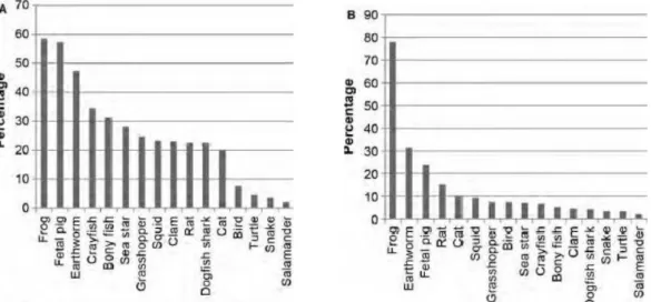
Another study that was done was on the subject of commonly used animals for dissection exercises. Teachers and students were asked about their use of dissection specimens. (Osenkowski et al. 2015). The result of the study was a report by teachers of frequent or occasional use of frogs (59%), fetal pigs (57%), and earthworms (47%), and other specimens for the past 2 years which is consistent to the top three animal specimen reported by King et al. (2004) (Figure 2-1A) (Osenkowski et al. 2015).
Student however has reported of commonly dissected frogs (78%), earthworms (31%), and fetal pigs (24%) (Figure 2-1B). Figure 2-1 below shows “prevalence of animals commonly used as dissection specimens in precollege biology education. Table (A) shows the percentage of teachers who have regularly or occasionally used animal species for dissection specimens during the past 2 years, among the teachers who practice dissection (n = 986). Table (B) shows the percentage of students who have dissected animal species shown (n = 500).” (Osenkowski et al. 2015).
Chapter 2: Literature Review
Figure 2-1 Shows prevalence of animals commonly used as dissection specimens in precollege biology education (Osenkowski et al. 2015:p342).
To better understand student preference toward animal dissection another study was conducted by Osekowski et al. About half of the students (48%) indicated that they do not prefer the use of alternatives while 37% did not know (2015, p. 343). The table below shows the result acquired from the study by Osenkowski et al. (2015).
Table 2-2 Shows percentage of students who agreed or disagreed with the following statements regarding the use of dissection and dissection alternatives
(Osenkowski et al. 2015:p344).
The research has shown that many of the students and teachers prefer animal dissection instead of alternatives. Even though almost half of the students agreed that animal dissection is compulsory, more than half of the students finds that student should be given options to opt out of dissecting animals. According to Osenkowski et al.
(2015), “it is possible that lack of awareness about dissection alternatives and their availability among the student population may be contributing to the low percentage of
Chapter 2: Literature Review
students requesting their use. Our survey revealed that 38% of students did not know whether dissection alternatives were available to them”.
2.3 Virtual Reality training in Neurosurgery
Observations has always been a method to learn in surgical education in the United States for more than a hundred years but it has been increasingly challenged recently regarding legal and ethical concerns for patient safety (Alaraj et al. 2011). The rising field of simulation and virtual training allows neurosurgical procedures to be practiced and taught outside of the operating room (OR) according to Alaraj et al.
(2011). In this paper, the evolution of virtual reality (VR) simulators for neurosurgical training will be discussed.
Neurosurgery is a complex operation as it involves overlapping structures in the brain and spine which may be hard to visualize (Alaraj et al. 2011). However, with the aid of 3-dimensional visualization of the structure, surgeons are able to do pre-operative planning with the main focus of exploring the patient data as much as possible and evaluating possible intervention procedures against that data. “This is accomplished by first creating 3D images from the patient's own diagnostic images, such as computed tomography (CT) scans and magnetic resonance images (MRI).” (Alaraj et al. 2011).
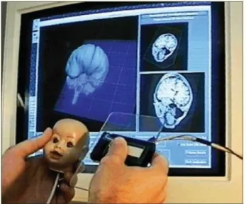
Figure 2-2 Shows a user selected a cutting plane of a mannequin head with the props interface showing the corresponding MRI image cuts part of preoperative
surgical planning. (Alaraj et al. 2011).
Chapter 2: Literature Review
This is only one of the virtual alternative that was researched on. There are more alternatives such as radio surgery, augmented reality surgery, Tele (remote) medicine, and augmented reality in intravascular neurosurgery. All of which could play a huge role in the advancement of neurosurgery without the need for observing an actual procedure in the OR.
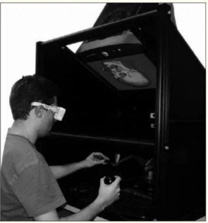
Figure 2-3 Showing the ImmersiveTouch™ system in operation. (Alaraj et al.
2011).
From the research conducted, it can be concluded that virtual reality is becoming increasingly important in neurosurgery. Not only does virtual environments overcome the ethical issues, it also improves the performance of neurosurgeons drastically.
However, some challenges and limitations still arise in the development of immersive and effective systems (Alaraj et al. 2011). According to Alaraj et al. (2011), “Open cranial operations provide a special challenge, since various tissue types may be concurrently present in the surgical field. These tissues are compacted in a three dimensional fashion, with a complex relationship to scalp, skull, and intracranial vessels”.
Chapter 2: Literature Review
The conducted research only applies to neurosurgery but if virtual reality could play such a huge role in the teaching and practice of neurosurgery which is considered to be a very complex field, why can’t the same alternative be used for dissections in classrooms which is less complex compared to neurosurgery. The research has shown the potential of virtual environment in replacing traditional dissection in contrary to what most teachers and students have disagreed with regarding alternatives in dissections (Oakley 2012).
The statement “A group at the University of Tokyo, however, has recently established that an interactive visualization system and a virtual workstation offered significantly improved diagnostic value over traditional radiological images” as concluded by Alaraj et al. (2011) makes it even more compelling that alternative can certainly be considered as the main approach and even top traditional methods in biological studies.
The only reason such high end technologies are not available in schools for educational purposes are mainly due to the cost of the technologies (Oakley 2012). If a similar technology that is produced to cater to high school students with reasonable price or even free, it would definitely be able to change the view of dissection as the main approach to teaching about animal anatomies. Such ideal is not far from reality with the current technologies that is available now.
Chapter 2: Literature Review
2.4 Dissection Lab Mobile Application Review
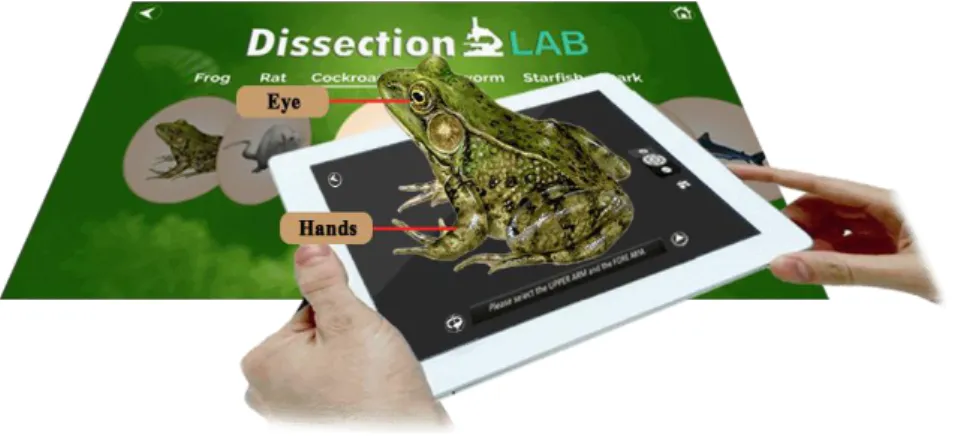
Dissection Lab is a mobile application available on the Android, iOS and PC that provides dissection process, facts and anatomy information of various animals to users. According to Navtek Solutions, creator of Dissection Lab, the application is created as an alternative to live animal dissection.
Figure 2-4 Promotional image of Dissection Lab from Navtek Solutions website The application provides 7 types of species for users to explore which includes frog, rat, cockroach, earthworm, starfish, shark and pigeon. However, the only free to access species is the frog and all the other species require users to unlock by paying for approximately RM 4.99 with a 6 months validity duration. This means that after 6 months, users have to unlock the species again.
Figure 2-5 Main screen of Dissection Lab
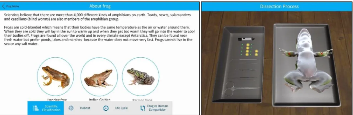
Selecting the options above shown in Figure 2-5 directs users to 3 options or to the shop to unlock the locked species. The 3 options include Dissection process, about species, and external anatomy (Figure 2-6).
Chapter 2: Literature Review
Figure 2-6 Learn about species screen (Left) and dissection process (right) The dissection process screen uses texts and computer generated voice to direct users on the process of the dissection. The directions start from where to pin the frog to where to cut the frog. The users pin the frog by selecting the pins and tapping on the area marked with ‘x’s and the users can cut the frog by drawing a line that follows the guideline shown on the frog. Users can also open up the frog using the forceps by dragging on the spots that are drag able. However, users are able to use the tools’
functions only when the directions are given.
Figure 2-7 External anatomy screen
The external anatomy screen (Figure 2-7) shows a 3D model of a frog that have labels of the frog’s anatomy. The labels will only appear when the users pressed on the area indicated to them. Once all the labels are shown, it will move on to showing deeper parts of the frog’s anatomy. The functions of the 3 screens do not only apply to the frog but also to other animal species shown in the main screen (Figure 2-5).
Chapter 2: Literature Review
2.5 Froggipedia iOS Application Review
Froggipedia is an application that is currently only available on iOS devices. It utilizes augmented reality and interactions with users to presents the life cycle and anatomical details of a frog. The application is solely focused on frog and it contains the life cycle, anatomical structures and the dissection process of a frog.
Figure 2-8 Life cycle screen
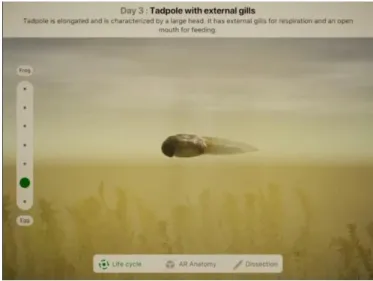
The main screen of the Froggipedia application is the life cycle screen. This screen allows users to navigate through the life cycle stages of the frog by selecting the dots on the left of the screen. There are 3 buttons located at the bottom of the screen that allows users to navigate to the other screens which is the AR anatomy screen and dissection screen. This 3 buttons remains at the bottom of the throughout all the screens.
Figure 2-9 AR anatomy screen
Chapter 2: Literature Review
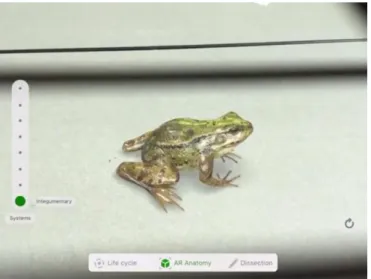
The screen shown in Figure 2-9 uses augmented reality to present a life-like 3D frog model to users. On the left are buttons that allow users to navigate through the external anatomy to the internal anatomy of the frog.
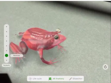
Figure 2-10 Muscular system of the frog in the AR anatomy screen
The figure above shows the muscular system of the frog. The screen allows users to view from the integumentary system to the digestive system of the frog. The 3D frog is constantly breathing and moving subtly and the inner systems actually mimics the breathing and movements of the frog.
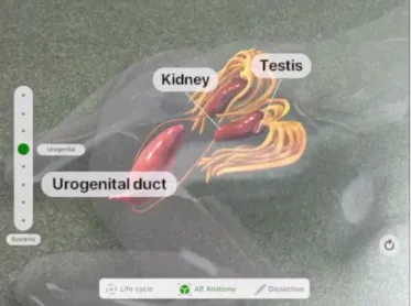
Figure 2-11 Muscular system of the frog in the AR anatomy screen
Whenever the user move closer to the frog, labels will appear to label the organs. It appears in a very neat and unintrusive manner.
Chapter 2: Literature Review
Figure 2-12 Dissection screen
The application also provides interactive dissection procedures to users. It will highlight the areas on the frog where users are supposed to perform certain actions and the textbox above the screen will provides instructions to the users. The users do not need to select any tools as the application will automatically display respective tools when the action such as tapping or drawing a line on the highlighted areas.
Figure 2-13 Organs identification
Once the frog is dissected, the texts above will start to ask users to identify the organs of the given characteristics. The users are required to drag the selected organs on to the tray on the right. If the selected organ is incorrect, the users will have to select again.
Users will not be penalized for any wrong guesses.
Chapter 3: Methodology
CHAPTER 3 : METHODOLOGY 3.1 Software Development Methodology
Figure 3-1 Incremental Development Model
The project will be based on incremental development where the application’s features will be developed iteratively and incrementally. Each features will be added incrementally and iteratively during the whole development phase until all of the requirements are met. By using the incremental development method, useful versions of the application can be generated quickly to be used for testing and refining. Based on the system design in chapter 3, the functions and features of the application can be separated into phases where each phase will deliver a new version of the application.
In table 3-1 on the following page, shows the work breakdown structure of the project. The table shows how the modules are separated into phases to be develop incrementally. On each phase, tests are done for each module to ensure that it is functioning correctly before moving on to the next phase. Every completed phase delivers a version of the application. Every version should be functional without any dependencies to the next version. However, the next version will enhance the modules of the previous versions.
Once all the phases are completed, the objectives of the project should have been achieved. Since an incremental model is used, new phases with more modules can always be added to improve the delivered application. This allows future improvements for the application.
Chapter 3: Methodology
Phased/Activity Description Deliverable
Phase 1 Develop the first version of the application.
Application ver. 1 Integrate augmented
reality
Integrate the augmented reality function with Vuforia using markers
Generating the virtual content
Augmented reality function
Develop Scalpel function
Get the touch pressure function
Create control pressure function
Create function to draw line on mesh
Generate a new mesh with a cut based on the line drawn
Scalpel function
Phase 2
Develop the second version of the application by adding new tool functions into the first version
Application ver. 2
Develop forceps function
Create function to select an area of edges that will be affected
Create function to check if edges are drag- able
Calculate offset displacement on surrounding vertices
Apply the displacement on selected edges
Apply offset displacement on surround vertices
Forceps function
Develop pin function Create function to select affected area of
vertices and lock vertices in place Pin function
Phase 3
Develop the third version of the application by adding the multiplayer system into the second version
Application ver. 3 Develop gestures
handler for tools
Implement gestures for the scalpel, forceps and pin
Gestures Handler
Develop multiplayer system
Create function to create a room on the network using the device’s IP address and the port number
Create function to discover created rooms on the network
Create function to join discovered rooms
Create function to assign role to users in the room
Create function to start the virtual dissection for every user in the same room
Create function to ensure the virtual dissection state is synced with all users in the same room
Multiplayer system
Table 3-1 Project work breakdown structure table
Chapter 3: Methodology
3.2 Tools Used
Software Development Environment
o Unity – Unity is a cross-platform game engine developed by Unity Technologies that allows application developed to be easily deployed to multiple platforms such as PC, web and mobile. The engine also provide ready-made assets, physics, intuitive tools and OpenGL based graphical rendering that greatly assist the development process.
Integrated Development Environment (IDE)
o Microsoft Visual Studio Community 2017 – Visual Studio Community 2017 is and IDE that is built on .NET framework which supports C# language that will be used as the main language for this project.
Software Development Kit (SDK)
o Vuforia – Vuforia is developed for integrating augmented reality into mobile applications. It is one of the most widely used platform for augmented reality applications. Vuforia utilizes ARCore and ARKit on devices that supports it otherwise, it will use its own technology which is on par with ARCore and ARKit. In addition to that, there is also a version that is baked into Unity.
o Photon – Photon is a SDK that allows networking in Unity. It allows cross platform and contains pre-made scripts for network connectivity.
This SDK contains a rich library for communications among devices.
Programming Language
o C# - C# was developed by Microsoft and is part of .NET and is commonly used for developing web and mobile application. It is a programming language that follows object-oriented and component- oriented programming disciplines.
Chapter 3: Methodology
3.3 System Design
3.3.1 System Overview
Figure 3-2 System Flowchart
The flowchart above is a simplified and improvised version of the flowchart shown in Figure 1-1 in section 1.5 of chapter 1. As described in section 1.5 of chapter 1, the system is made of 6 modules which is the augmented reality module, scalpel tool module, forceps tool module, pin too module, gestures handling module and the multiplayer system module. The sections highlighted above shows which module will handle which functions and processes. Each module will be explained in section 3.2.
Augmented reality module
Multiplayer system module
3 of the tools modules
Gestures handling module
Chapter 3: Methodology
3.3.2 Module Descriptions
3.3.2.1 Augmented Reality Module
Figure 3-3 Augmented Reality Module
The augmented reality module works by performing image recognition to detect the marker and generating the virtual content and augment it onto the detected marker.
This type of augmented reality is called marker-based augmented reality. The marker is detected by using the camera to capture the placement of marker and on every frame the marker will be compared to the target image that was set as the marker. The feature points of the target image will be used to identify whether the captured marker is the target image. If it is, the virtual content will be rendered and the placement of the virtual content will follow the placement of the marker. This creates an illusion of augmented reality. In this project, the processes desribed are handled by the Vuforia framework which contains the APIs and tools needed by the processes. The integration of the framework into the project will be described in chapter 5 section 5.3.1.
3.3.2.2 Scalpel Tool Module
Figure 3-4 Scalpel Tool Module
Chapter 3: Methodology
The scalpel tool is a tool that enables users to perform the action of cutting the 3D model. The cutting mechanism does not perform any actual mesh deformation cuts on the mesh itself but instead unlocks the function to move the cut areas when the user has “cut” the pre-defined cut areas.
Figure 3-5 Illustration of a cut line on a 2D polygon
Based on the figure above, if the user draws a line outside of the dotted line, it will not be considered as a valid cut line and if the line is drawn on the dotted line, it will be considered as a valid cut and will unlock the respective cut areas to allow the user to manipulate it. For example, the ability to drag the skin of the cut area with the forceps.
The pre-defined cut method has been used in many applications especially applications that requires users to dissect objects. This method can be easily implemented by aligning the drawn line of the cursor which is in 2D space to the 3D object in the 3D space. However, the same cannot be done when augmented reality is applied to the 3D object as the angle and placement of the 3D object will constantly be changed due to movements of users.
Figure 3-6 Front view of 3D model (left) and angled view of 3D model (right) The figure above shows the 3D model of a frog with pre-defined cut lines. The white lines indicate the initial area of the pre-defined cut of the image on the left but when the angle and position of the 3D model is changed (as shown in the image on the right), it can be observed that the white lines are no longer aligned with the pre-defined cut.
Chapter 3: Methodology
Figure 3-7 Drawn line on mesh with nearest vertices selected
Therefore, the method used in this project is to draw the line on the mesh itself instead. The line drawn is used to determined which vertices of the mesh are selected by finding the nearest vertices to the line. The vertices will then be compared to the vertices of the pre-defined cut line. If the vertices matches, then the cut will be considered as a valid cut.
Figure 3-8 Points formed from drawn line on mesh with nearest vertices selected In order to find the nearest vertex to the line, the line has to first be converted to points. The points can then be used to find the nearest vertex of each of the points.
The points are formed at an interval to ensure that a limited amount of points are formed to save computational resources. Once the points are formed, the nearest vertex to each points can be determined by finding the smallest square magnitude of the vertex to the point. If the same vertex is selected by different points, the vertex will only be compared once during the comparison phase.
Chapter 3: Methodology
The setback of this method is that the time complexity of the operation will be O(n*m) which means the time required will increase quadractically depending on the number of vertices (n) and number of points (m). The solution to this is to first check which triangle the point is located at and compare the 3 vertices of the triangle instead.
This will reduce the time complexity increase rate of the operation by 3 times as the number of triangles is 3 times lesser that the number of vertices.
3.3.2.3 Forceps Tool Module
Figure 3-9 Forceps tool module flowchart
The forceps tool allows user to move and rotate parts of a 3D object in the scene.
The forceps tool work by detecting the position of a touch on a drag-able mesh and then pointing the mesh towards the touch position or moving the mesh if it is moveable. The forceps tool does not deform the mesh directly but instead manipulates the “bone” that is associated with the mesh. Further implementation details on assigning the bones are described in chapter 5 section 5.2.2.
Figure 3-10 Frog skin flap dragged at touch point (white dot)
The figure above shows how the mesh if affected when the “bone” of the skin flap on the right rotate towards the touch point (white dot). This method contains 2 steps where the first step is to assign the mouse movements to the touch point and the second step is to calculate the rotation required for the mesh to rotate towards the touch point.
The touch point is defined as the area where the mouse is supposed to be pointing on the mesh.
Chapter 3: Methodology
Figure 3-11 Mouse pointing direction (dotted line) to touch point (white dot) The calculation to apply the mouse movement to the touch point is made up of 2 variables which is the mouse position in 3D space and the mouse offset from the touch point. The equation below shows the calculation of the mouse offset and touch point:
𝑂⃗ = 𝐼 – 𝑀⃗⃗
𝑇⃗ = 𝑀⃗⃗ + 𝑂⃗
𝑂⃗ − 𝑚𝑜𝑢𝑠𝑒 𝑜𝑓𝑓𝑠𝑒𝑡 𝑀⃗⃗ − 𝑚𝑜𝑢𝑠𝑒 𝑝𝑜𝑠𝑖𝑡𝑖𝑜𝑛 𝑖𝑛 3𝐷 𝑠𝑝𝑎𝑐𝑒 𝐼 − 𝑖𝑛𝑖𝑡𝑖𝑎𝑙 𝑡𝑜𝑢𝑐ℎ 𝑝𝑜𝑖𝑛𝑡 𝑇⃗ − 𝑐𝑢𝑟𝑟𝑒𝑛𝑡 𝑡𝑜𝑢𝑐ℎ 𝑝𝑜𝑖𝑛𝑡
Once the new touch point has been obtained, the rotation of the mesh can be calculated by calculating the amount of rotation required to rotate towards the touch point. For this project, the function Transform.LookAt() provided by Unity’s API was used. However, there are cases where the rotation needs to be applied to one axis only. For example, when rotating the skin flap shown in Figure 3-10 , only the local Y axis was rotated (the axis pointing to the head). In this case, the calculation of the touch point has to take the axis into consideration. The formula below converts the touch point to the position where only one axis is needed to rotate:
𝑇⃗ = 𝑇⃗ − 𝐴 [𝐴 ∙ (𝑇⃗ − 𝑃⃗ )]
𝐴 − 𝑎𝑥𝑖𝑠 𝑡𝑎𝑘𝑒𝑛 𝑖𝑛𝑡𝑜 𝑐𝑜𝑛𝑠𝑖𝑑𝑒𝑟𝑎𝑡𝑖𝑜𝑛 𝑃⃗ − 𝑡𝑎𝑟𝑔𝑒𝑡 𝑚𝑒𝑠ℎ 𝑝𝑜𝑠𝑖𝑡𝑖𝑜𝑛
The new touch point can then be applied to the look at rotation equation or in this case, the Transform.LookAt() function. When calculating the rotation, it is also important to take the axis as the world up axis. For example, in Figure 3-10, the world up axis (which
Chapter 3: Methodology
is the Y axis (0, 1, 0)) is the Z axis (0, 0, 1) of the mesh. Therefore, it is important to specify the world up axis in the calculation according to the local axis of the mesh.
Since the mouse position is relative to the camera in the 3D space, this method of moving the mesh works well with augmented reality implemented too.
3.3.2.4 Pin Tool Module
Figure 3-12 Pin Tool Module Flowchart
The concept of the pin tool module is to prevent interactions of the forceps tool with any interactable parts of the 3D model. The flow of the pin tool module start by receiving the touch input from the user. Once a touch is detected, it is then used to check whether the touch is on an interactable part of the 3D model. If it is, it will pin it and prevent any interaction from the forceps. However if the selected part is already pinned, it will remove the pin instead and allows interaction with the forceps once again.
3.3.2.5 Multiplayer System Module
Figure 3-13 Host Migration Architecture
Internet/LAN
Client
Client
Client Master Client
Server
Chapter 3: Methodology
The multiplayer system uses the host migration concept to connect multiple users in the virtual environment. The user that created the room will be the master client.
The master client is the client that other client sync to. However, all clients are connected to a centralized server. In this project, the Photon’s Unity Networking server will be used.
Figure 3-14 Multiplayer System Module Flowchart
In Figure 3-14, it shows how the clients (users) and the master client (host) are connected through the server. The architecture is similar to a client-server architecture.
With host migration architecture, the system can switch Master Client to other users when the Master Client disconnects or when the Master Client initiates the switch function. There are two methods in Photon’s library which supports this function which is a function called SetMasterClient() and its call back method called OnMasterClientSwitched(). The SetMasterClient() function allows the Master Client to be switched and the OnMasterClientSwitched() method is called when the Master Client is switched. This allows notification and state changes such as UI updates to be initiated when the Master Client is switched.
Chapter 3: Methodology
3.3.2.6 Gesture Handling Module
Figure 3-15 Gestures Flowcharts
The gesture handling module is used to assign gestures to activate the functions of the tools. This module allows users to interact with the 3D model using the tools without selecting it. For example, by using the pinching gesture, users can use the forceps tool without selecting it first. In this project, the dragging gesture performs the scalpel function, the pinching gesture performs the forceps function, and the long press gesture performs the pin function as shown in the figure above.
Chapter 3: Methodology
3.4 User Interface Design
The figures below shows the user interface design of the application. The following figures shows the placement of the buttons for every screen and the functions of the elements in the screen are described in this section.
Figure 3-16 Main screen with “Start Dissection button” and “Multiplayer”
button
The main screen of the application contains the application title, a “Start Dissection” button that will load the dissection screen in Figure 3-16 and a
“Multiplayer” button that will load the screen with the multiplayer lobby screen shown in Figure 3-18.
Figure 3-17 Dissection screen
The dissection screen shown in Figure 3-17 contains the list of tools available located on the left. The background will be the environment captured by the camera and the virtual specimen to be dissected will be augmented onto the captured environment.
Chapter 3: Methodology
Figure 3-18 Multiplayer lobby screen
The multiplayer lobby screen contains a list of rooms that is currently being broadcasted on the network. The list contains the room names and number of players currently in the room. A “Create Room” button located at the bottom of the screen to allow user to host a room and broadcast the rooms on the network connected by the device. When the button is pressed, the pop up shown in Figure 3-19 will be shown.
Users can click on a room listed to join the room and the application will redirect users to the “Waiting screen” shown in Figure 3-21.
Figure 3-19 Create room popup
The figure above shows the popup that allows user to create a room. It contains an input field for the room name and another input field for the password. Users can leave the room name field and password field blank if they do not wish to set any room name and password. If the room name field is empty, a default name will be generated based on the room order (e.g. Room 1). The “Create” button will create a room and be broadcasted onto the network. When a room is created, users will be redirected to the
“Waiting screen” shown in Figure 3-21.
Chapter 3: Methodology
Figure 3-20 Waiting screen - Instructor view
The waiting screen of the Instructor’s view shows a list of players in the room.
Each player’s name contains an “L” icon at the right used to indicate that the user is the instructor. There are two buttons at the bottom which is the “Exit Room” and “Start Dissection” button. The “Exit Room” button allows the user to exit the room and the
“Start Dissection” button loads the dissection screen shown in Figure 3-17.
Figure 3-21 Waiting screen – Student view
The figure above shows the waiting screen of the Student’s view. It contains a list of player’s name and an “Exit Room” button at the left hand corner to exit the room.
The instructor of the room will be indicated by the “L” icon placed on the right.
Chapter 3: Methodology
3.5 Implementations
3.5.1 Software Environment
The end product of this project is a mobile application that is integrated with augmented reality. To achieve that, Unity was used as the main engine for the development as it supports both ARCore and Vuforia framework. The mobile application is written in C# along with Vuforia as the main framework for the augmented reality module. Vuforia is cross-platform and is neatly integrated with Unity. As such, Vuforia’s APIs are easily called within Unity itself without any extra setups needed. Unity also uses OpenGL as its graphical rendering framework which allows Unity to render in 3D and perform mesh deformation related operations.
3.5.2 Pre-Implementation Processes
Before the implementing the modules, the 3D objects have to be created first.
The 3D models used in this project are acquired from open source websites and was then edited using Blender which is an open source 3D modelling software. The aim of this process is not to create a realistic 3D model but instead to create a 3D model that can be used to demonstrate the functionalities of the modules in this project. Deforming meshes by code is very tedious and time consuming therefore this process is to ease the mesh deformation processes required by the modules of this project.
1. Predefining Cuts
Figure 3-22 A cavity with 2 skin flaps in a 3D model of a frog Skin flaps
Chapter 3: Methodology
Since it is very rare that a dissectible 3D model can be found on the open source websites, modifications are required for the relevant 3D models found. In this case, a 3D model of a frog was found and it was modified to have a cavity around the chest area to allocate space for the organs of the frog. The 2 skin flaps were also remained to allow the cavity to be covered up again with the aim of hiding the cavity from being detected when covered up.
2. Assigning Bones
Figure 3-23 Simple bone rig for the skin flaps
In order to allow movement in different areas of the mesh, bone rigs have to be applied to the mesh. Each bones are assigned to separate groups of vertices that it will affect. For the purpose of this project, a simple rig is assigned to the flaps of the cavity described in the previous section. This allows the flaps to be opened and closed by rotating the bones on the Y axis (the axis parallel to the head and feet).
Figure 3-24 Bones weight relation with mesh (top view)
Bones
Chapter 3: Methodology
The figure above shows how the bones are associated to the mesh in terms of weightage.
In blender, the weightage which range from 0 (dark blue) to 1 (red) indicates how much the bone will affect the areas of the mesh.
3. Creating the Anatomy
Figure 3-25 Mock up 3D models of the organs of a frog
The figure above shows the mock up 3D models of the organs that form the basic anatomy of a frog. The models created in this section is to allow the demonstration of how users can interact with the 3D model in the implementation of the following modules. The anatomy of the frog created may not be entirely accurate as it is only for demonstration purposes.
3.5.3 Implementation of Modules
3.5.3.1 Implementing the Augmented Reality Module
The augmented reality module is the module that allows the 3D object in the scene to be augmented to the users’ surrounding through the device’s camera. The framework that is used in this project is the Vuforia framework. The integration of Vuforia with Unity has eased the process of implementing this module.
Chapter 3: Methodology
Figure 3-26 Image target created in Vuforia Developer Portal
The first step to implementing this module is to create a marker first. In Vuforia, the marker is known as an image target. The image target is created by using an image that as distinct shapes and is easily recognizable through image recognition. Then the image can be imported into the Vuforia Developer Portal Target Manager which will create a Unity package that can be imported into the Unity project. Once this is done, the image target can then be detected by Vuforia’s augmented reality camera in Unity.
Figure 3-27 Unity scene with AR camera and image target with 3D frog model The figure above shows the image target and AR camera in a Unity scene. The AR camera can be created from the GameObject > Vuforia Engine > AR Camera menu.
The 3D model of the frog was also parented to the image target. It is important to parent the image target to the 3D model in order for the hiding and rendering of the augmented reality to work properly when the image target is detected or hidden.
Chapter 3: Methodology
3.5.3.2 Implementing the Scalpel Tool Module 1. Predefining Vertices of Cuts of a Mesh
The scalpel tool module works by selecting vertices of the 3D mesh and checking whether the selected vertices is part of a cut on the mesh. Since there are no way to check whether the vertices are part of a cut, the vertices of a cut need to be stored somewhere first. Then, when the user select a set of vertices, it can be compared to the stored vertices. Unity does not provide any API or tools to select vertices of a mesh in the editor nor during runtime. So, to select the vertices in the editor, a custom editor called VertexSelector was written. A custom editor is a script that enables the customization of the Unity editor. Once the vertices are selected, the vertices can then be added to an object called VertexLibrary, where all the vertices stored in a class object called CutVertices and the class object is stored in a list in the VertexLibrary. So, every set of vertices of a cut is an individual CutVertices object. For instance, if an object contains 3 cuts, there will be 3 CutVertices object in the list of the VertexLibrary.
Figure 3-28 Selection of vertices flowchart
Once the vertex library has been populated with vertices of all the cuts in a mesh, the library can then be used to compare with the selected vertices during runtime.
2. Implementing vertex selection mechanism
Figure 3-29 Casting a ray from mouse screen point to 3D mesh