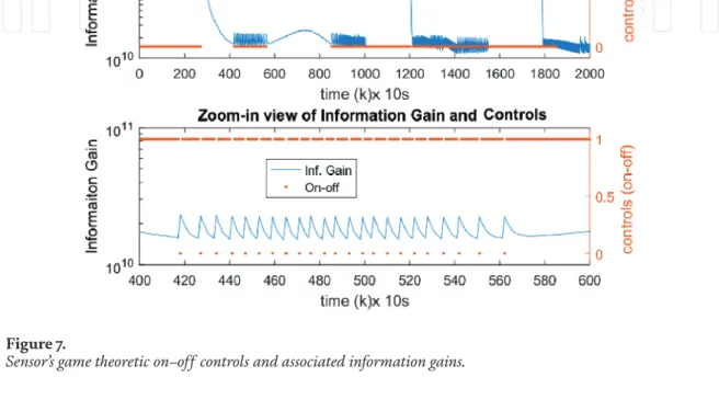
Markov game – The space conflicting situation is derived from the Markov game structure [5, 6], where the system state is represented by distributions rather than deterministic values. Manifold Learning for Data Level Sensor Fusion – The raw sensor data is generally high dimensional.
Numerical results and discussion 1 Training data generation
Results and analysis of our CNN_DNN neural networks
Understanding the significance of these weights during the training process with subsequent validation is very important in CNN model design, leading to a more reasonable interpretation when deploying the model. Therefore, there are some trends for most weights and anomaly filters during training processes, especially the middle layers of deep convolutional neural networks.
Background and introduction
PL Subsystem 5—PL TT&CS: Similar to BTT&CS but for mission PL;. PL Subsystem 14—PL Structure & Mechanism Subsystem (BS&MS): Provide structure and mechanism to assemble all PL components of the mission.
Existing satellite systems, related interfaces and standards
Existing satellite bus, related interfaces and standards
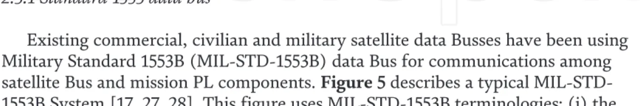
The main communication link between a satellite bus and a mission PL is the communication data bus. Currently, most satellite buses use the standard 1553 data bus for data communication between bus components and between the satellite bus and mission PL components.
Existing mission payload, related interfaces and standards
PL "Safe Mode" is a combined mission PL component hardware and software configuration that must be designed to protect the PL. PL Command SAFE Mode will be required to protect and preserve mission PL components under abnormal and resource constrained conditions. Similar to the design of the satellite bus interfaces, for military applications, the mission PL components are tightly coupled using the contractor's custom interfaces.
For commercial applications, PL mission components are loosely coupled using widely accepted open interfaces.
Existing data busses
The SpW standard is a self-managing serial protocol that provides high data rates from 2 to 400 Mbps and a low-power serial interface using LVDS1 drivers with distances up to 30 feet, while offering a flexible, simple user interface. Figure 6 shows typical uses of SpW data bus with PCD&HS, SpW router and SpW cables to connect PL mission components.
Industry view: open vs. close interfaces and standards
Open Interface design
To ensure that the interface design is open, the interface design must not be owned by the contractor and must use either popular open interface standards that are widely accepted by the aerospace industry or open interface standards with little market support and closely used by the aerospace industry. Thus, a popular open interface design is a non-proprietary design that uses the popular open interface standard widely used by the aerospace industry. The benefits of an open interface design for the satellite buyers are (i) enhancing competition, allowing different space vendors (or contractors) to build open satellite bus and mission PL subsystem components, (ii) ease of refresh and technology upgrade allowing subsystem components to be swapped without impacting the overall system, (iii) easy adaptation to new requirements and operational threats, (iv) integration of innovation by enabling operational flexibility to quickly configure and reconfigure a mission PL to meet rapidly changing operational requirements, (v) enabling cost savings and cost avoidance during the design and maintenance phases by reusing technology and Software/Hardware/Middleware (SW/HW/MW) components and using existing standardized HW/SW/MW parts and modules, and (vi) improving interoperability where separable HW/SW/MW modules can be changed independently.
Close interface design
Popular open standards
Advisory Committee on Space Data Systems (CCSDS) Standards: is a multinational forum for the development of communication and data system standards for spaceflight. MIL-STD-1553 Standard: is a military standard published by the US Department of Defense that defines the mechanical, electrical and functional characteristics of a serial data bus. SpaceWire Standard: is a spacecraft communications network standard based in part on the IEEE 1355 standard for communications.
NASA/SMC/Aerospace Hosted Payload Interface Design (HPID): this design guideline provides a prospective instrument developer with technical
Interfaces design challenges and MOSA implementation
- Interface design and practical design challenges
- Introduction to MOSA
- DOD guidance
- MOSA implementation and assessment tools
Proposed implementation approach to design and build satellite systems that allows buyers to independently acquire satellite bus and Mission PL. This step is achieved by identifying all potential KOSSs from the satellite bus to any mission PLs, ie. the KOSSs selected must be independent of mission types. The system integrator performs satellite Bus and mission PL integration using the approved interface specification.
DOD has also developed MOSA tools to assist MOSA implementation and assessment of military satellite Bus and mission PL "Openness".
Future resilient and robust satellite system architectures
A potential modular open satellite bus architecture solution
BC&DHS-5 Memory Storage Unit BC&DHS-6 Spacecraft Control Processor BC&DHS-7 Bus Telemetry Conditioning. BTT&CS-5 SGLS S-Band RX/TX Assembly BTT&CS-6 SGLS Baseband Signal Processing. BEPS-2 Battery Assembly (BA) Not recommended for interface standardization; Battery size will vary depending on the mission profile.
The error handling processing interface is in this category and is not recommended for standardization.
A potential modular open Mission payload architecture solution
Conclusion
Although the preparation of this work was not funded by The Aerospace Corporation, but the author acknowledges that the work presented in this chapter was based. PCom-RFS-1 PL LNA component Not recommended for interface standardization due to many variations between systems/. PcCm-RFS-4 PL Up/Down Converters Recommended for Open Interface Standardization PCom-RFS-5 Tunable IF Down.
PDPS-1 PL ADC/DAC Not recommended for interface standardization due to many variations between systems.
Introduction
This chapter discusses two microsatellite system design approaches, namely the Technical University of Berlin legacy and the University of Surrey legacy. The choices of microsatellites that will be compared in this chapter will be those produced around the same time, so that the technology being compared is essentially the same and in orbit. To be comparable, the microsatellite system choices to be compared are those that were produced around the same time, so the available technology is largely the same.
The second part explains how the University of Surrey heritage satellite design examples were selected and what satellite design parameters were used in the comparison.
University of Surrey heritages
Thailand's Mahanakorn University collaborated with the University of Surrey in the joint development of TMSat, which was launched in 1998 [9]. Singapore's Nanyang Technological University (NTU) has partnered with the University of Surrey to jointly develop the satellite subsystem for UoSAT-12. However, the satellite is not a micro-class and is therefore not chosen as a model for the design of the University of Surrey satellite system in this chapter.
Turkey's experience with the University of Surrey's satellite design is when its space research institute, TUBITAK-UZAY (formerly BILTEN TUBITAK-ODTU), jointly developed BILSAT-1.
Technical University of Berlin heritages
The aluminum trays also act as a supporting structure so that the rest of the satellites' components, such as reaction wheels and attitude sensors, can be laid out around them. After all components are integrated, the solar panels and/or other exterior panels made of lighter materials can be used to cover the satellites.
Analysis
- Power generation and storage
- Main computer
- Attitude control subsystem
- Propulsion subsystem
- Payload
- Mission data downlink
- Payload computer
- Orbit determination
- System level parameters
There are also differences in the attitude control sensor between the University of Surrey's design heritage. For University of Surrey legacy satellites, only KITSAT-3 uses reaction wheels in 3-axis configuration. For the University of Surrey legacy, the data rate started at 3 Mbps in KITSAT-3 and increased to 100 Mbps in RASAT.
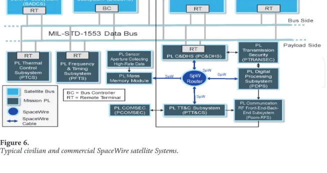
The density of the (weight/volume) satellites is shown in Figure 7, indicating that the TU Berlin heritage satellites are more compact than the University of Surrey heritage satellites.
Conclusions
In: Proceedings of the 3rd International Conference on Recent Advances in Space Technologies (RAST 2007); Istanbul, Turkey; June 14-16, 2007. Proceedings of the 3rd International Conference on Recent Advances in Space Technologies (RAST); Istanbul, Turkey; June 14-16, 2007. In: Proceedings of the 4S Symposium: Small Satellites, Systems and Services; La Rochelle, France Saifudin MA, Mukhayadi M.
This chapter focuses on the application requirements of a new generation intelligent avionics system for future communications satellites and adopts an "open" architecture of "centralized control, distributed measurement and propulsion, and 'modular' software and hardware.
System structure
- Overall architecture design
- High-performance computing hardware architecture
- Dynamically reconfigurable task scheduling
- Software partition protection mechanism design
This chapter focuses on the application requirements of a new generation intelligent avionics system for future communication satellites and adopts an open architecture of "centralized control, distributed measurement and propulsion, and modular design of software and hardware". The universal, standardized and expandable system of intelligent avionics is built on the basis of basic modular elements of open hardware modules, open software components and industrially standardized internal and external busses. The architecture of the newly proposed next-generation intelligent communication satellite avionics system is shown in Figure 1. A high-performance on-board processor is used to improve the computing performance of the avionics system.
Therefore, the design of the system software architecture of the electronic system must comply with the reliable partition protection to avoid the above problems.
Menu system composition
Satellite management unit
For data rates higher than 10 Mbps, the industry trend is moving towards the SpaceWire data bus, which can handle data rates up to 400 Mbps. With autonomous failover enabled, when the standby machine fails, the fault-tolerant module automatically completes the SMU failover and shuts down the failed one. In the event that autonomous switching is not enabled, in the event of a failure of the duty machine, the ground station performs a power failure and the machine is switched over.
Integrated service unit
Data bus network
The ISU and other equipment as the RT end receive instructions and send the collected telemetry data to the SMU.
Failure detection isolation and recovery (FDIR) design
- FDIR design goals and principles
- Failure levels
- FDIR scheme
- FDIR processing requirements for satellites in orbit
- FDIR processing
Once a high-level failure occurs, all detection of same-level and low-level failures is suspended until the recovery sequence is complete. When the FDIR enable flag is "disabled", the status of the module is not detected. When the FDIR enable flag is "enabled", the status of the service module is detected.
If the fault detection condition is met on the watchdog module and the FDIR recovery enable flag is "disabled", the health status of the module is set to unhealthy.
Impacts on next-generation avionics system
Judging processing conditions: First, determine the scope of failure detection according to the requirements of the satellite in orbit and ground control. This design can improve intra-satellite network failure tolerance and achieve efficient resource allocation and scheduling. If the control subsystem is still in ground control mode, it will seriously affect the safety of the satellite.
In addition, this approach also reduces the differences in hardware products and improves the fault tolerance of the internal satellite network, which meets the increasing network requirements of the satellite.