Inquiries regarding the use of the book should be addressed to the Rights and Permissions Department of INTECHOPEN LIMITED ([email protected]). Additional information is available at the end of the chapter http://dx.doi.org/10.5772/intechopen.80623.
Introductory Chapter: New Challenges in High-Voltage Engineering
Introduction
Due to equivalent capacitance and inductance, the natural frequency of a high voltage cable can be excited by harmonic content of a transient impulse leading to destructive overvoltage known as. High voltage testing is performed under loading or artificial impulses such as switching or lightning waveforms.
Author details
Contamination can form from dust, moisture and salt combined in industrial or coastal areas where maintenance intervals can be very long. The characteristics of the test waveforms must be defined in a way that the actual conditions can be realized.
A Review of Polypropylene and Polypropylene/
Inorganic Nanocomposites for HVDC Cable Insulation
Provisional chapter
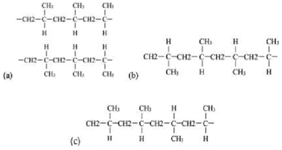
Polypropylene and its feasibility study for insulation materials of high-voltage DC cables
- Physical and chemical properties of polypropylene materials
- Feasibility of polypropylene applied to insulation material for high-voltage DC cable
Currently, the commercial application of polypropylene-based materials as the main insulating material for high-voltage DC cables is still in the research and development stage. Moreover, most researchers are concerned about improving the mechanical properties of polypropylene.
Research status of polypropylene-based nanocomposites for HVDC cable insulation materials
- Study on dielectric properties of polypropylene nanocomposites 1. Space charge
- Thermal conductivity of polypropylene nanocomposites
- Study on mechanical properties of polypropylene nanocomposites
- Effect of nanofillers on properties of polypropylene composites
- Effect of nanofillers on the properties of polypropylene composites under aging conditions
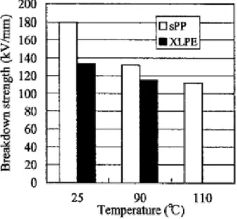
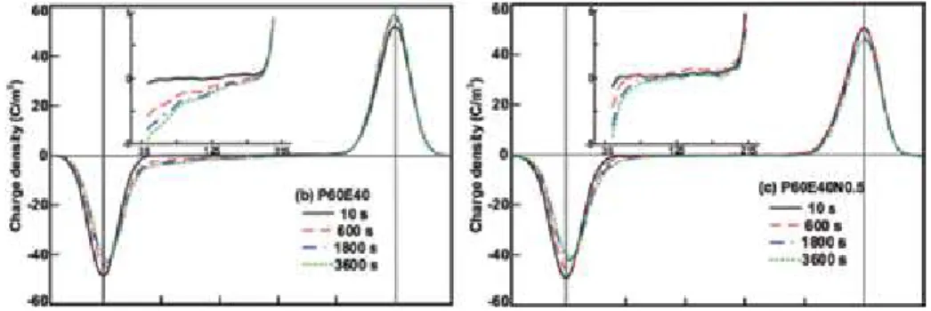
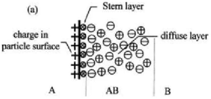
Distortion of the electric field caused by the accumulation of charge in space increases the field strength required for the composite to break through. Toughness results in a significant increase in the tensile strength and elongation at break of the composite [34].
Conclusions
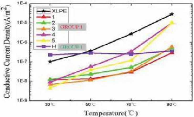
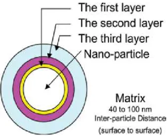
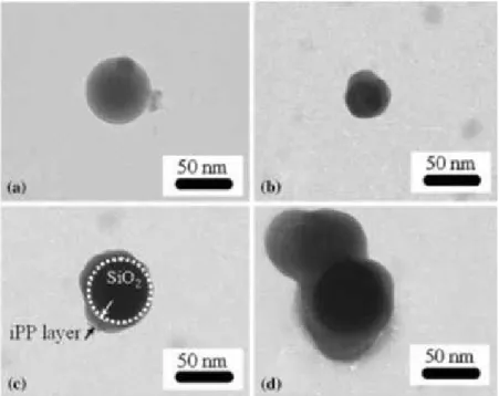
In addition, nanoparticles with a lamellar structure have a higher surface energy, so that during the transition carriers are trapped in the interstitial traps between the nanoparticle and the polymer matrix, which limits the migration of electrons and holes. In the composite material, when the amount of nanometer doping is large, the overlap of the "media double layer" structure between the nanoparticles can be increased, the space charge transfer is promoted, and the electrical conductivity of the nanocomposite material becomes large. The tensile strength is still about 12% higher than that of pure polypropylene and there is no significant change in the dielectric loss factor, and the DC conductivity is only slightly increased [37].
During normal operation, the insulation medium of high-voltage DC cables can also be affected by the coupling field consisting of voltage deformation field, electric field, magnetic field and temperature field. There is no corresponding experimental research on the dielectric, thermal and mechanical properties of polypropylene and its nanocomposites under coupled field. Polypropylene material is easily affected by electricity, heat, or light, aging, cable preparation methods, process flow and other effects on the performance of polypropylene nano-composite insulation material, the future still needs to carry out the corresponding research work.
In: Manufacturing and Characteristics Proceedings of the 7th International Conference on Properties and Applications of Dielectric Materials. Space charge formation and its modified electric field under varying applied voltage and temperature gradient in XLPE cable. Effect of opposite polarity on space charge evolution in polypropylene with different concentration of natural and synthetic nanoclay.
The effect of the addition of polypropylene grafted SiO2, nanoparticle on the crystallization behavior of isotactic polypropylene. Influences of polypropylene grafted onto SiO2 nanoparticles on the crystallization behavior and mechanical properties of polypropylene/SiO2 nanocomposites. Surface modified MgO nanoparticle improves the mechanical and DC electrical properties of polypropylene/polyolefin elastomer nano-dielectrics.
The Performance of Insulation and Arc Interruption of the Environmentally Friendly Gas CF 3 I
The Performance of Insulation and Arc Interruption of the Environmentally Friendly Gas CF 3 I
- Comparison of CF 3 I and its mixtures with SF 6 and its mixtures on insulation property
- The radial temperature distribution characteristics and leading energy transport process of CF 3 I nozzle arc
- The arc’s characteristics near the arc-zero area
- Analysis of the by-product after CF 3 I interrupts arc
- Spectrum analysis to the arc-later compositions of CF 3 I
- Characteristic analysis of CF 3 I decomposing products
- Conclusions
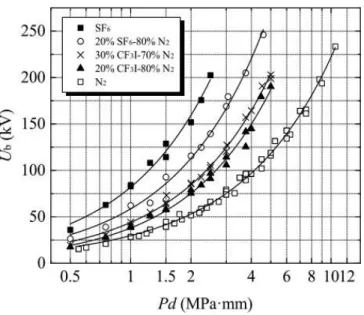
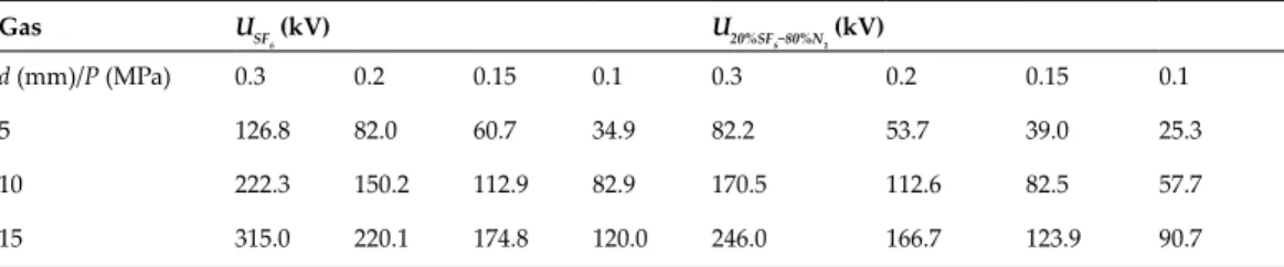
Insulation Performance and Arc Interruption of Environmentally Friendly Gas CF3I 25 http://dx.doi.org/10.5772/intechopen.79968. Comparison of insulating properties of CF3I-N2 mixture with SF6 and SF6-N2 mixture in a slightly non-uniform electric field. Comparison of insulating properties of CF3I-N2 gas mixtures with SF6 and SF6-N2 gas mixtures in a highly non-uniform electric field.
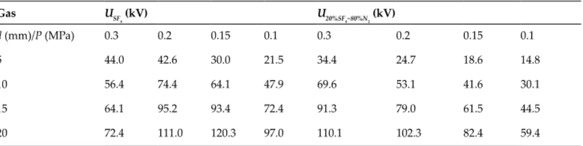
The insulation and arc breaking performance of the environmentally friendly gas CF3I 29 http://dx.doi.org/10.5772/intechopen.79968. Due to the change of the breakdown voltage with the gap distance, the breakdown voltage of CF3I-N2 and CF3I-CO2 gas mixtures increases linearly with the increase of the gap, and the rate of increase is proportional to the pressure in a slightly non-uniform electric field. The insulation and arc breaking performance of the environmentally friendly gas CF3I 33 http://dx.doi.org/10.5772/intechopen.79968.
The insulation and arc breaking performance of the environmentally friendly gas CF3I 35 http://dx.doi.org/10.5772/intechopen.79968. The insulation and arc breaking performance of the environmentally friendly gas CF3I 37 http://dx.doi.org/10.5772/intechopen.79968.
Acknowledgements
After adjusting to operating conditions or structure size of the electrical equipment, CF3I gas mixtures can achieve equivalent insulation level of SF6, and at the same time, the fluidity temperature can satisfy the operating conditions of switching equipment. Because CF3I-N2 gas mixtures will not affect global warming, it can solve environmental unfriendly problems and realize the green upgrade of the electrical equipment. Therefore, we suggest that 20–30% CF3I-N2 gas mixtures can be applied as SF6 alternatives in medium and low voltage electrical apparatus.
The performance of insulation and arc interruption of the environmentally friendly gas CF3I 39 http://dx.doi.org/10.5772/intechopen.79968. Analysis of the characteristics of DC nozzle arcs in air and guidance for the search for SF6 replacement gas. Fundamental research on the application of ambient baked insulating gas CF3I in the electrical equipment [PhD thesis].
Analysis for Higher Voltage at Downstream Node, Negative Line Loss and Active and Reactive
Components of Capacitor Current, and Impact of Harmonic Resonance
Analysis for Higher Voltage at Downstream Node, Negative Line Loss and Active and Reactive
Components of Capacitor Current, and Impact of Harmonic Resonance
Analogy on higher voltage at downstream node
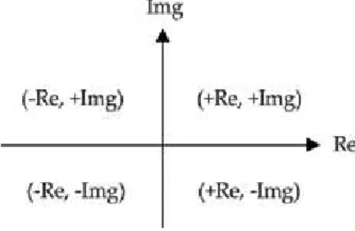
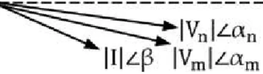
ℜe Vign and Im g Vign are respectively real and imaginary components of Vign; ℜe½ ΔVi�andimg½Δvi�are, respectively, realand imaginary components of Δvi .. q ffiffiteste Evs ffisffi�ℜe½ ½ ½ ½ ½ ½ ½ ½ ½ ½ ½ ½ ½ ½ ½ �M �In �Im g �In ��ℜe, � IGN ��2 þ�IM G V� IGN If real components of upstream node voltage (vign) and voltage drop ðδviþ Have the SamesignAndImaginary Components of Upstreamnodevolage (vign) Andvolteam (ΔVi) also have the same sign, then the upstream node pole time must be higher than the downstream Node. 4), if real components of upstream node voltage Vign and voltage drop ðΔViÞ have opposite signs and imaginary components of upstream node voltage Vign and voltage dropðΔViÞ also have opposite signs, then upstream node voltage must be lower than downstream node voltage. imaginary components of upstream node voltage Vign and voltage drop ðΔViÞ have the opposite sign unsigned components of upstream node voltage Vign and voltage drop ðΔViÞ have the opposite sign, but imaginary components of upstream node voltage Vig n and voltage drop ðΔViÞlow voltage upstream or downstream voltage can be the same sign upstream and downstream. If the upstream node voltage phase Vign and voltage drop phase ðΔViÞ lie in the same quadrant, real components of upstream node voltage Vign and voltage drop ðΔViÞ will have the same sign, and imaginary components of Vign and ΔVi will also have the same sign; in this case the upstream must not be a high voltage.
If the node voltage phasor Vign and the voltage drop phasor ðΔViÞ lie in two different quadrants that are completely opposite to each other (the first and third quadrants or the second and fourth quadrants), then the real components of the voltage Vign and the voltage drop ðΔViÞ will have the opposite sign, and the imaginary components Vign and ΔVi will also have the opposite sign; in this case the voltage on. Location of Upstream Node Voltage (Vign) and Voltage Drop (ΔVi) The upstream node voltage level relative to. Conditions that the voltage of the upstream node is higher or lower than the voltage of the downstream node.
Analogy on negative line loss
If the upstream node voltage is lower than the downstream node voltageðj jVn < jVm jÞthat can happen in an AC system as shown in Section 2, then it confirms that j jVn cos θn < jVm jcos θm (i.e. active line loss) must be negative. Vm cos θm (i.e. PLoss < 0) if the upstream node voltage is less than the downstream node voltage j j. If the downstream node voltage is less than the upstream node voltage, ðj jVn > jVm jÞ, then this confirms that active line loss cannot be negative.
If the voltage of the lower node is higher than the voltage of the upper node j jVn < jVm j, then it is confirmed that j jVn cos θn < jVm jcosθm, i.e., the active line loss must be negative. The power factor of the downstream node will be lower than the power factor of the upstream node if the voltage of the downstream node leads both the voltage of the upstream node and the line current or the voltage of the downstream node lags behind the voltage of the upstream node and the line current. Lag/Lead Status Power Factor (Pf) Voltage Level Status Negative Line Loss Occurrence DownstreamdevoltagelagUpstream Node Pf Downstream If Downstream Node Voltage Possibility and Leads Current Line Node Voltage < Node Occurrence Upstream of.
Active and reactive components of capacitor current
In the line loss calculation above, it can be seen that although the voltage (2474.55 V) at the upstream node is higher than the voltage (2474.07 V) at the downstream node, the power factor at the upstream node is less than the power factor at the downstream node. Now the capacitor current angle relative to the system reference is equal to the capacitor bus voltage angle plus 90°; the cosine and sine value of this capacitor current angle form the active and reactive current component of the capacitor current, respectively, where the capacitor current is reactive only with respect to the voltage of the capacitor bus. It should be noted here that if Kirchhoff's current law is applied to the capacitor bus, given that the capacitor current is only reactive, then Kirchhoff's current law is not sufficient.
If the angle of capacitor current with respect to the system reference is presented resulting in both real and imaginary components of capacitor current, then it satisfies Kirchhoff's current law. Here, if thecapacitorcurrentisassumedtobeonlyReactiveCurrent, i.e. ICAP, then it does not satisfy Kirchhoff's current law ðplineCurrent ÞloadCurrent þCapacitorCurrent ¼0) At thebus675.capacitorcurrenticap leadbusvoltagev by90�; app. Here we can see that power consumed by the load is equal to the capacitor's output power plus power injected through the line, while line current is equal to capacitor current plus load current.
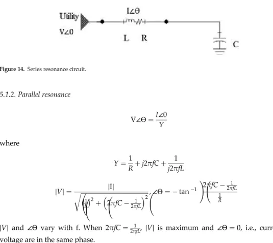
Impact of harmonic resonance on capacitor
Analysis for the highest voltage at the bottom node, the negative line loss and the active and reactive components of. MVASC is the available fault capacitance at the capacitor location and MVARC is the rated reactive power of the capacitor. Harmonic current can have a negative effect on the capacitor resulting in overload, overheating and voltage stress.
Motor loads in the system make the corresponding impedance lower under the capacitor placement because motor loads at the short circuit inject current back into the system and add parallel circuits. The following are the prevailing methods of mitigating the harmonic distortions:. i) Reactor: Reactor is a simple and cost effective technique to reduce the harmonics injected by non-linear loads. This is also known as harmonic trap filters. On six pulse drives it is used as an independent part. It is also used for multiple single-phase non-linear loads.
Conclusion
A capacitor supplies only reactive power, but its current has both real and imaginary components with respect to the system reference. In terms of the capacitor bus voltage, all current in a capacitor is reactive. With series resonant capacitor the current is very high and with parallel resonance the voltage across the capacitor is very high which can burst the capacitor. Improving the power quality of the wind power system using low-cost topology. International Journal ofModelling andSimulation Carpaneto E, Chicco G, Akilimali JS.
Effect of load type on power consumption and line losses in a voltage reduction program. In: ProceedingsofConferenceonNorthAmericanPowerSymposium (NAPS). 6] IEEE PES Distribution System Analysis Subcommittee Working Group. URL: http://ewh.ieee.org/soc/pes/dsacom/testfeeders/index.html. 24 Factorial design for the combined effect of ambient temperature and price, size, and phase kVAr capacitor on line loss.