Inquiries regarding the use of the book should be directed to the rights and permissions department of INTECHOPEN LIMITED ([email protected]). The book also gives an overview of the linear and nonlinear aspects of plasma physics.
Introduction
The basic parameters of the plasma state are briefly given, as well as the classification of plasma types: classical-quantum, ideal-non-ideal, etc. However, despite tremendous efforts, the task of plasma confinement has not yet been fully resolved.
Plasma parameters
Plasma oscillations .1 Langmuir frequency
In this case, the ratio of the distance where the interaction between the particles is significant compared to the average distance between the particles is small [8]:. where a is the molecular size, rh i is the average distance between particles, and n is the density). Outside the Debye radius, the interaction between charged particles is exponentially small and can be neglected.
Degenerate plasma
The condition for the applicability of the gas approximation in a non-degenerate state is ΛP¼e2nT1=3 <<1. In conclusion, we give an estimate of the applicability conditions of the gas approximation (10) and (12) for different plasmas.
Plasma description
Self-consistent approach
In the diagram ln n vs ln T this condition gives line 1 which divides the region of the degenerate plasma from the non-degenerate (classical) state. A self-consistent interaction of the electromagnetic field and charge carriers takes place in plasma-like media.
Waves in plasma and plasma-like media
Under linear consideration in isotropic media (media with no preferred directions), we actually have proportional dependence of the plasma current on the electric field or. However, if the plasma is in the external field, it loses isotropy, and the relationship between j and E becomes much more complicated.
Electrostatic waves in plasma
This highlights the importance of considering the solutions in the form of traveling waves. With this, many cases are encountered in plasma, in which solution of the initial problem gives complex frequencyω¼ω0þiω00for real k.
The simplest plasma models
One-particle model
In fact, the "average" particle model describes the plasma well in the considered frequency range. Indeed, this model was used by Langmuir to describe the oscillatory properties of gas-discharge plasmas.
Two-fluid hydrodynamic: relative electron-ion motion
In the opposite case, the ion contribution to (47) results in small root corrections that describe the proper oscillations of the flow electron (48). In fact, the instability is due to the resonance of the negative energy wave with the ion oscillations.
Overview of propulsion devices and rocket equation
This chapter discussed the application of plasma physics in the field of electric drives and types. Unfortunately, the mass ratio cannot be increased enough to avoid payload problems in a space mission, so for a given mass ratio, the exhaust velocity U!ex of the propellant must be of the order of dυ.
Thrust, impulse and efficiency
Electrothermal thrusters
After simplifying, we get ln mf. 3) The above rocket equation provides the relationship between mission speed and the mass of propellant mp¼mimf required for a given mission.
Electromagnetic thrusters
Electrostatic thrusters
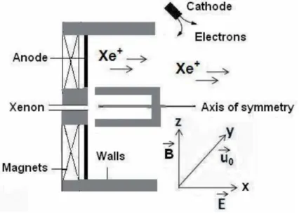
Hall thruster operation
The magnetic field of the order of 150 Gauss is applied to produce a closed drift of electrons in the channel. Hall thruster has high thrust resolution and is used for adjusting satellite location on board.
Spacecraft issues
Types of Hall plasma thruster
Dielectric wall thruster or stationary plasma thruster
Thruster with anode layer
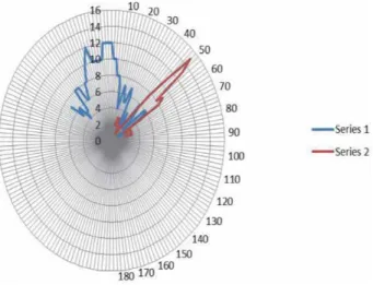
Review of status of current research and development in the subject The range of the oscillations lies from few kHz to MHz in the acceleration
The amplitudes of the waves and instabilities are attributed by the scale lengths of the plasma density and magnetic field and other parameters. These fluctuations in the Hall thruster determine the efficiency of the system and can affect the divergence of the ion beam and the transfer of electrons across.
Ion stream speed study for electrostatic thruster
Conclusions
In both feeding cases, the plasma is essentially produced due to the absorption of power by the electrons from the space-time dependent MW electric field. The behavior pattern of the electric field during plasma evolution can help us to comment on the different modes/mechanisms of MW coupling involved in the formation of plasma particles and their containment scenarios.
Basic theory of microwave plasma interaction
- Microwave propagation in plasmas
- Electron cyclotron resonance (ECR)
- Wave propagation in warm plasma condition
- Electrostatic wave
- Mode conversion theory
- Parametric decay
Microwave propagation in the plasma is affected by the dielectric strength of the plasma medium. In that case, the attenuation of the microwave field is greatly affected by the plasma particles.
Simulation modeling of MW interaction in plasma
The exponential term on the right-hand side represents that the Landau damping will be small for small value of kλD. The phenomenon of Landau damping is applicable to both the case of electrons and ions. For modeling the MW interaction during plasma evolution, a schematic of the computational domain is shown in Figure 2 .
Results and discussion
Time evolution of plasma with power deposition
But the intensity of the E-field is decreasing with time due to the shielding of the plasma. The anisotropic behavior of plasma bulk electron temperature even in excess plasma implies ECR heating [31, 32].
E r -field evolution with time
In all the figures, a strong inhomogeneity in the Er-field profile indicates the power absorption locations. The difference in the radial variation of the Er field comes from the variation of the resonance magnetic field contour as shown in Figure 3.
E z -field evolution in plasma with time
Figure 10(a) shows that the polarity in the inhomogeneous part of the electric field becomes opposite for two different time periods, 20 and 85µs. The shift of the inhomogeneous part of the electric field is inward direction.
Validation with experiment
Methods of experiment
In the present experiment, the MW plasma reactor of the experimental setup is a cylindrical cavity (Figure 11) with a length of 107 mm and a diameter of 88 mm. The response of the microwave set power at a frequency of 2.45 GHz is recorded at the directional coupling gate by a microwave spectrum analyzer (SA) circuit.
Comparison of experimental results with simulation
A hot Teby a Langmuir probe diagnostic measurement at the same set power level shows it to be 72 eV. It is observed that the plasma densities for the power levels set above are �1.8–2 times smaller than the simulated data.
Conclusion
Therefore, the plasma frequency decreases as the frequency of the plasma antenna decreases. Below this point, the thermal noise of the plasma antenna is greater than a metal antenna.
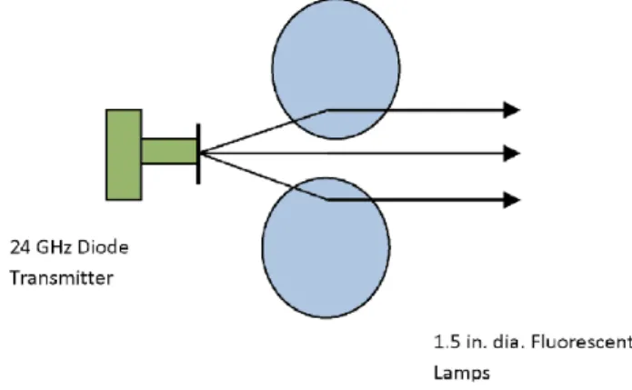
Focusing antenna beams with the physics of refraction through plasma
In the following sections we show our work on antenna beam focusing, beam propagation and beam steering using refraction of RF waves in a plasma. Schematic showing the beam spread of a custom-made 3-inch-diameter plasma tube antenna at 10 GHz.
Steering antenna beams with the physics of refraction through plasma
For a lens to work properly, the wavelength must be small compared to the physical dimensions of the lens, or in our case the plasma tube. Note that the plasma focus increases the beam amplitude by a factor of two compared to no plasma (3 dB gain).
Pulsed plasma antenna circuitry
We have developed a pulsed voltage doubler circuit, which allows us to use a lower voltage DC power supply for the input power to the pulsing circuit using a modified Marx Generator. A DC power source charges the capacitor, the IGBT pulse current switch delivers short 1μs pulses to the plasma tube.
Power, current, and voltage requirements in pulsing excitations The plasma antenna requires a relatively high voltage, low current power
Current, Current, and Voltage Requirements in Pulsed Excitations The plasma antenna requires relatively high voltage, low current power. Power, Current, and Voltage Requirements in Pulsed Excitations The plasma antenna requires relatively high voltage and low power consumption. The plasma antenna requires relatively high voltage and low power consumption.
Conclusions
Various plasma diagnostic methods are briefly discussed, and the framework of the test charge technique is effectively used as a diagnostic tool to investigate interaction potentials in Lorentzian plasmas, of which components they are. Using space-time Fourier transforms for the linearized coupled Vlasov-Poisson equations, the test charge potential is derived with a modified response function due to energetic ions and electrons.
Plasma diagnostic methods
However, in some plasmas (especially at high temperatures) it is not possible to use material probes to determine plasma parameters such as plasma electron density. This justifies the use of infrared radiation in the tokamak and ultraviolet radiation to measure the plasma electron density in the LPP.
Dusty plasma and test charge technique
Load test techniques [12, 13] can be used to study the protection of test loads in impinging [14] and turbulent plasmas [15], the electric field [16] and the far-field potential of a test load in a non-uniform magnetoplasma [17], the excitations of the wake field in the test plasma, the two excitations of the wake field in the load plasma, the relative voltage loss 1-8] loads [20], etc. Any plasma medium can be physically polarized by the test charge to create a perfect control if thermal disturbances are absent in the plasma system.
Power-law Lorentzian distribution function (df)
Furthermore, oscillating wake fields can be excited behind the test charge [37] in a collisionless unmagnetized plasma with Maxwellian electrons and ions. Later, Shukla and Rao [39] analyzed the WF, DH and FF potentials of test charge in a colloidal Maxwell plasma accounting for the flowing ions and dust grains.
Kinetic model for Lorentzian dusty plasmas
- Slow moving test charge response
- Short-range DH and long-range FF potentials
- Resonating test charge response
- Short-range DH and long-range WF potentials
- Fast moving test charge response
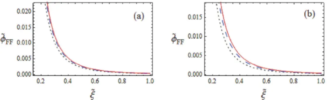
Furthermore, post-test wetts are loaded slightly earlier as shown in Figure 6(b) due to the strong dependence of superthermal ions on the effective shielding length compared to . Now it is clear that if the test charge is moving very fast, then there is no shielding around it in the dusty Lorentzian plasma.
Conclusion
A study of low-energy electrons in the evening sector of the magnetosphere with OGO 1 and OGO 3. However, in the presence of any critical physical situation (critical point), the non-linearity of the KdV equation disappears and the amplitude of the waves reaches infinity.
The Korteweg-de Vries equation
Therefore, this speed is equal to the speed of ion-sound waves cs. It is clear that the height, width and velocity of the pulse are proportional to u0, p1u0 and u0.
Damped force KdV equation
Phase velocity and nonlinear evolution equation
It is observed that the solution produces solitary waves and the amplitude of the solitary waves increases with increasing value of the parameter f0. In Figure 4, the damping force equation KdV is shown by Eq. 65) for different values of dust ion collision.
Damped KdV Burgers equation
Perturbation
In the absence of C and D, ie. for C=0 and D=0, equation (76) has the form of the well-known KdV equation with a solitary wave solution. where the amplitude of solitary waves is ϕm=3MA0 and the width of solitary waves is W=2 . q, where M0 is the ion-acoustic solitary wave speed or Mach number. Therefore, the form of the slow time dependence of the ion acoustic solitary wave solution of the DKdVB equation is
Damped force MKdV equation
The solution of the Eq. Therefore, the slow time dependence form of the ion acoustic solitary wave solution of the DKdVB Eq. 78) with respect to τand using Eq. The slow time dependence form of the ion acoustic waves solution of the DFMKdV Eq.
Damped force Zakharov-Kuznetsov equation
For simplicity, assume that S2 is a linear function of ξ such as S2¼ f0ξcosð Þ þωτ P, where P is a constant and f0,ω denote the strength and frequency of the source, respectively. Motivated by these works, we here consider the source term as S2¼ Bf0ðeζþfξþgηÞcosð Þ,ωτ. where f0 and ω denote the strength and frequency of the source term, respectively.
Conclusions
The analytical solitary wave solution of Eq. where f0 and ω indicate the strength and frequency of the source expression, respectively. Thus, the amplitude and width of the solitary wave structure change with different plasma parameters.