The research contained in this thesis was completed by the candidate while based in the discipline of Mechanical Engineering, School of the College of Agriculture, Engineering and Science, University of KwaZulu-Natal, Howard College, South Africa. This thesis does not contain text, graphics or tables copied and pasted from the Internet, unless specifically acknowledged, and the source is detailed in the thesis and in the References sections.
PUBLICATIONS
HAND ANATOMY AND CHARACTERISTICS
- The human hand
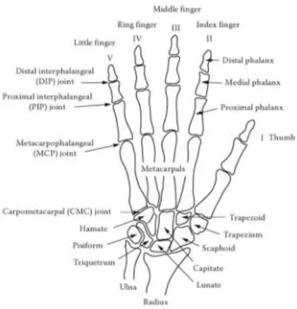
- Anatomy of the hand and wrist
- The fingers
- Finger joints
- The wrist
- Muscles of the forearm, wrist and hand
- Flexor tendon pulley systems
- How muscles work – hand and wrist muscles
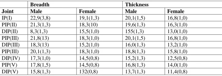
- Finger and hand anthropometry data
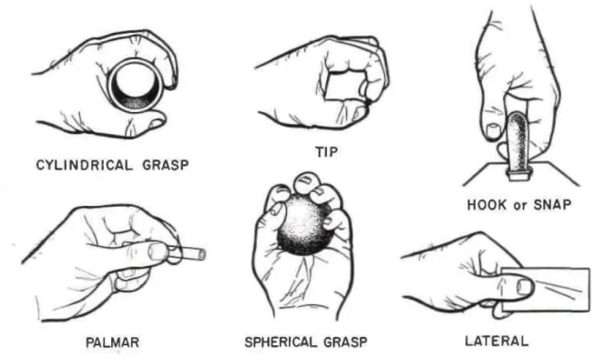
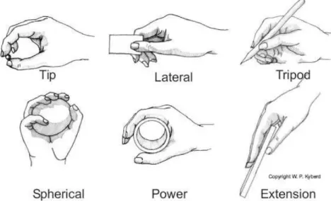
- Grasping
- Hand grip strength
Their proximal surfaces form a biconvex surface which articulates with the distal extremity of the radius. The internal muscles of the hand are divided into the thenar, hypothenar and midpalmar muscle groups.
A REVIEW OF MODERN PROSTHETIC HANDS
- Bebionic hand
- Michelangelo hand
- I-Limb hand
- Mechanical hands
- Open source 3D printed hands
- Grip 5 Prehensor
Mechanical hands are usually body powered, usually using a strap that goes over the amputee's shoulder. This body driven hand with Bob as the pilot came first ahead of the Michelangelo and I-limbed hands mentioned here earlier in the competition.
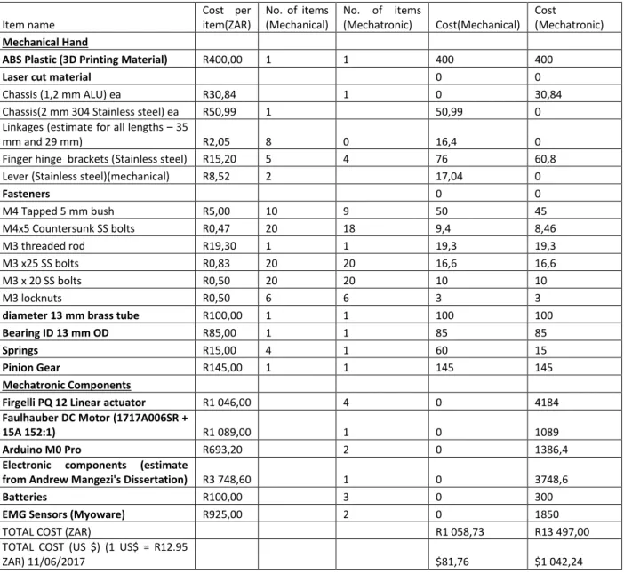
THE COST OF PROSTHETICS
Other things that influence the design are the production costs and also the time it takes to develop the hand.
RESEARCH OBJECTIVES AND SPECIFICATIONS
Weight: The prosthetic hand should be as light as possible (less than 750 g) so that the amputee can operate it without much effort. Therefore, the cost of construction and materials should be kept to a minimum so that any user can purchase it.
CONTRIBUTIONS
Grip strength and grip patterns: Grip strength should be similar to the human hand which has a maximum of about 55 kg. Finger design and hand design: the fingers and hand should be modular in their construction so that if there is any repair work that needs to be done it can be done quickly and easily.
CHAPTER SUMMARY
Hand tests: the hand should perform well experimentally and be able to handle the grip types in practice. Since a study of the human hand has been carried out, as well as a study of modern prosthetic hands and their technologies, the design of a low-cost modular prosthetic hand should be carried out and conceptualized.
MECHATRONIC DESIGN OPTIONS
- Finger actuation
- Motor selection
- Mechatronic design specification for prototype and final design
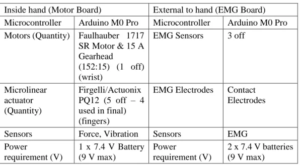
A finger control method had to be the next step in the decision-making process. Electronic board: Two separate electronic boards should be developed: one for the motors and one for the EMG sensors (input sensors).
MATERIAL SELECTION FOR PROSTHETICS
- Wood, leather and cloth
- Plastics
- Fibre reinforcements
- Metals
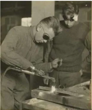
- Laser cutting
Steel is strong but relatively heavy and is used to make small components that depend on material strength rather than geometry. ABS is the stronger and stiffer of the two and was used in the design of Touch Prosthetic Hands 1 and 2.
MECHANICAL CONCEPTUAL DESIGN
- Prototype mechanical design
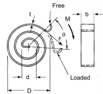
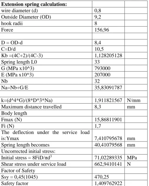
- Spring calculation using a clock spring as in prototype mechanical hand
- Finger actuation
There are a few more options for using a prosthetic arm, which is a mechanical arm, than a tendon system. The table below shows the pros and cons of both, this was decided early in the design phase and determined the course of the design.
PRELIMINARY PROTOTYPE
- Mechatronic prototype
- Hand
- Electronics
- Safety specification: general safety measures
- Prototype testing
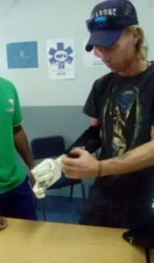
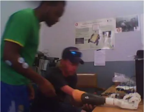
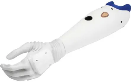
It receives signals from the user through EMG electrodes, which are then translated into finger and wrist movement within the hand. A description of the specifications of the Touch hand 3 prototype is presented in the following sections. Two sets of three electrodes are used to control the operation of the prosthetic hand.
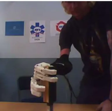
This required more fine motor skills than placing the chalk duster on the plastic container and was a good test showing the capabilities of the prototype hand.
CHAPTER SUMMARY
Some rather complicated grasping and manipulation was done by placing a chalk duster on top of a plastic cylinder. Problems with the design could be seen in the fact that the electronic system was slow to respond, although with a little practice the amputee was able to get things working properly. It took some time to understand how the EMG system works and to flex his remaining muscles in the stump. of practice. The electrical circuits in the final design include the H-bridge, EMG sensors, external sensors (temperature, pressure and vibration) and sensory feedback (vibration motor).
In the final design, two microcontrollers were used: one to receive and decode the information from the EMG sensors and other sensors used in the hand, and a second microcontroller to implement the response in the hand motors.
ELECTRONIC SYSTEM
- MCU (Microprocessor)
- Sensors
- EMG sensors and amplifiers
- EMG sensors
- Temperature sensors
- Pressure or force sensors
- Vibration sensors
- Motors
- DC Motor
- Micro-servo linear actuators
- PCB control boards
- EMG control board
- Motors control board
- Batteries
Sensors in the hand are needed to measure the EMG signal coming from the remaining muscles of the amputee's stump in order to position the fingers. EMG sensors typically consist of three parts: one negative, one positive, and a ground electrode. The electrodes are connected to contact electrodes that stick to the skin of the person being tested. The DC motor in hand was the Faulhauber 1717SR motor in combination with the 15 A Faulhauber planetary gearbox (152:1).
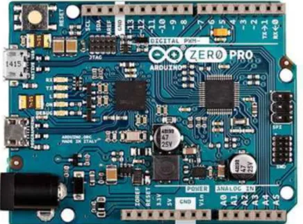
A voltage regulator was used in the final control board to maintain a regulated voltage of 5 V to the Arduino M0 Pro.
ELECTRONIC SPECIFICATIONS
CHAPTER SUMMARY
The design of the mechanical hand required the Touch hand 3 to be modular in order to adapt between a mechatronic and a mechanical hand. The following sections present the design optimization of a generic chassis or shell, which may include mechanical and mechatronic designs, along with stress analysis on the various components that make up the arm.
OPTIMISATION
- Intermediate mechatronic design
In the hand example, the thumb is able to move in the x and y directions. Another option explored would be the use of two brackets which allow manual or motorized positioning of the thumb in time in the x-direction. On the back of the hand then access is given to the actuators, wrist motor, Arduino and electronic boards.
It is the most modular and offers the best access to all the mechanical and electronic equipment in the hand.
FINAL GENERIC SHELL DESIGN
- Chassis
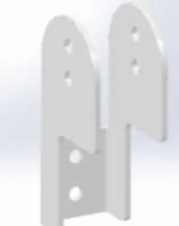
- Finger hinges
- Fingers
- Wrist
- Cover
- Finite element analysis of generic Shell
- Stainless steel 2 mm finger hinges
- Chassis, 1.6 mm 6016 H14 Aluminium
- Finger stress analysis: ABS plastic
- Thumb bracket analysis
- Covers stress analysis
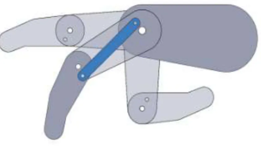
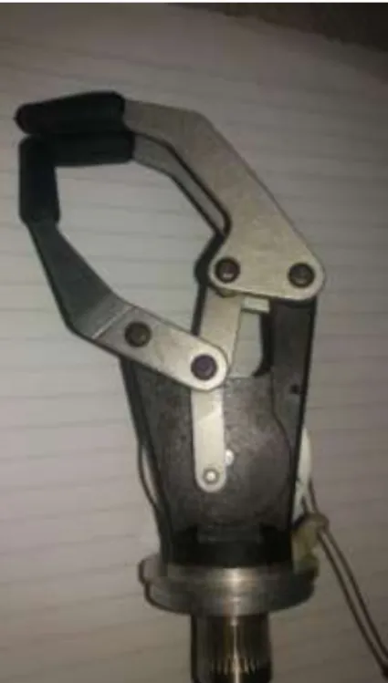
The final toe design has the toe in two parts, unlike the prototype toe which was split into four parts. In this final design, the actuator connects directly to the proximal portion of the finger, eliminating the need for an additional connection as used in the preliminary prototype design. For the aluminum chassis, which was the first option for the mechatronic hand design, when the chassis is loaded with 500 N, as shown in Figure 4-19, the aluminum provides a yield stress of 90 MPa, the main problem being deformation, as in Figure 4- 20, the aluminum is deformed by 6 mm at the top of the case when it is loaded with 50 kg.
The displacement is a maximum at the end of the thumb bracket when loaded as in Figure 4-25.
FINAL MECHANICAL DESIGN
- Spring calculations
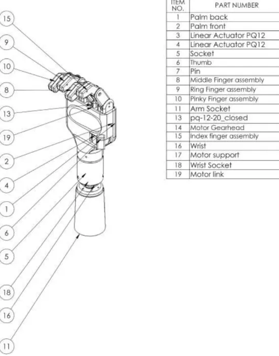
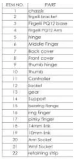
- Final design assembly: mechanical hand
- FEA on final mechanical design
- Finger stress analysis
The initial spring tension must also be known, this is the energy required to open the spring alone. Basically, one method of determining spring length would be as follows: In this case the spring length also depended on the space available at the back of the hand, the distance to the base of the chassis. The following procedure can be followed for the final assembly of the mechanical hand design.
To the other set of links are added tension springs which are attached to the base of the chassis by eye hooks.
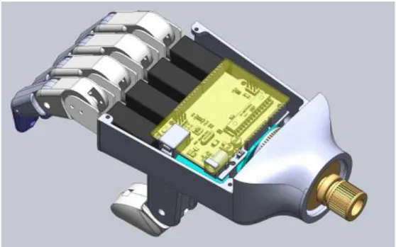
FINAL MECHATRONIC DESIGN
- Electronics and control system
- Final design assembly
Connect the PQ12 linear actuator to the chassis using the connection bracket bolted to the chassis with the M3 lock nut. Press the bearing into the bearing support and secure this to the underside of the chassis in the 8 holes provided with M3 x 15mm countersunk screws. Insert brass tubing through the bearing and gear and slide this entire assembly through the chassis plate.
Attach the gear to the motor with the 3mm screw so that the motor is pressed onto the gear holding the chassis in place.
CHAPTER SUMMARY
Statics looks at the study of bodies at rest, while dynamics is involved with bodies in motion. Newton's laws are used in a study of the forces involved in magnitude, application, and direction.
BIOMECHANICS OF THE HAND AND FINGERS
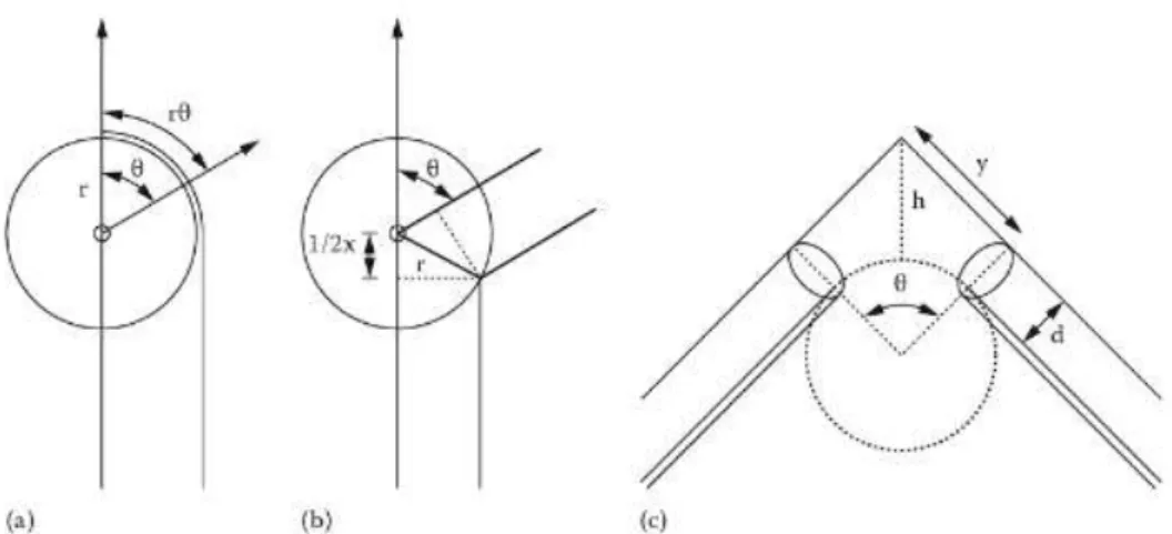
- Static pulley tendon models
- Model 1
- Model 2
- Model 3
- Dynamic tendon pulley models
- Hand finger kinematics
- Description of link and joint parameters
Biomechanics or mechanics is the science concerned with forces and their effects as applied to biological systems. 𝐹𝑁 is the normal force exerted on a tendon and R is the radius of curvature around supporting tissue. I is the moment of inertia of the hand in flexion and extension, and 𝜃̈ is the angular acceleration.
Dynamics is the study of forces and torques and their effect on motion while kinematics studies the motion of objects.
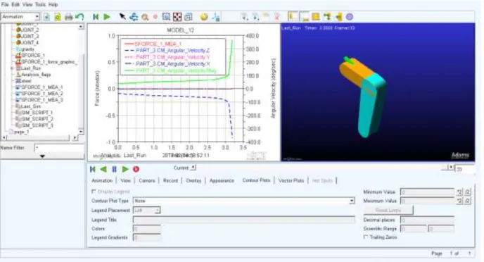
KINEMATIC ANALYSIS
One is able to watch an animation of the finger movement by looking at the graph result for each moving element.
CHAPTER SUMMARY
To test the hand, it must be tested against a known test in which human hands as well as prosthetic hands can be evaluated. In this case, the Yale Open hand tests and the SHAP object tests seem to be sufficient for testing the hand.
INITIAL TESTS
- Designing tests for a prosthetic hand
- INITIAL RESULTS
- Mechatronic hand initial test
- Mechatronic hand initial test
- Mechanical hand initial test
- Mechatronic hand grasp acquisition tests (initial) results
- Mechanical Hand grasp acquisition tests (initial) results
- Dynamometer tests
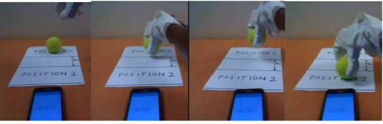
Figures 6-5 through 6-8 show the video analysis of the initial tests performed on the mechatronic hand with objects based on those used in the Yale Open hand tests. Hand grip analysis was performed based on the Yale open hand tests initially to determine the ability of the prosthetic hands. The hand dynamometer used for the tests is shown in Figure 6-13, which measures a reading from the mechanical hand.
Test results of the mechatronic and mechanical hand dynamometer tests against two human subjects can be seen in Table 6-5.
SHAP ABSTRACT OBJECT TESTS
- SHAP TEST RESULTS
- Mechatronic SHAP abstract object test
- Mechanical SHAP abstract object test
The results are analyzed according to the hand's performance in the tests. Table 6-6 shows the SHAP test results for the mechatronic arm, where the arm was able to pick up all objects, the tip grasp was the longest to complete at 13 seconds because the spring object used was heavier for it. grasping hand. Video analysis shows that the mechanical and mechatronic arms can perform similar grasp patterns, with the only grasp that was not executed being the mechanical arm's failure to perform an extensive grasp.
This thesis has looked at the more fundamental aspects of the SHAP Abstract object test - i.e.
CHAPTER SUMMARY
The design part of the project looked at preliminary possible designs for both the mechanical and mechatronic hands. The results of the video analysis were documented and the prototype design was analyzed. The electronic system for a prototype and final design of the prosthetic hand has been developed and its specifications have been documented.
The mechatronic design of the hand is built around housing the electronics in the final design of the hand.
COMPARASION OF HANDS
In conclusion, extensive successful testing of the final designs of mechanical and mechatronic arms was carried out with positive results. These are interchangeable, except for the joints and main proximal phalanx of the little finger, and are also interchangeable between the mechanical and mechatronic hand. Thumb Positions - We decided that the final thumb design would be a static (non-actuated) thumb, although the thumb tip can be manually positioned for different grips.
Designing the thumb in this way allowed for almost all types of grip without the complexity of operation and also featured a modular design.
FUTURE WORK
- Mechatronic option
- Mechanical option
CHAPTER SUMMARY
Garrett, J.W. Anthropometry of the Hands of Male Air Force Personnel”; AMRL-TR- 69-42, Aerospace Medical Research Laboratory, Wright-Patterson AFB. A review of the measurement of grip strength in clinical and epidemiological studies: towards a standardized approach.”, Age Aging. M., (2016) "Comparative Clinical Evaluation of the Yale Multigrasp Hand" , 6th IEEE RAS/EMBS International Conference on Biomedical Robotics and Biomechatronics (BioRob) June 2629, UTown, Singapore.
The mechanical hand of the 16th century German knight still allowed him to hold his sword and bridle after losing a limb in battle; 2014 http://www.dailymail.co.uk/sciencetech/article-3303868/Now-iron-grip-Mechanical-hand-belonging-16th-century-German-knight-allowed-hold-sword-reins.html.