CSIR Mining Technology, Johannesburg, South Africa
Summary
Although hard rock is not usually associated with large creep deformation, sig- ni®cant time-dependent behaviour is observed in the tabular excavations of the South African gold mines. Time-dependent closure data was collected in stopes of the Ventersdorp Contact Reef and Vaal Reef. This data typically consists of a primary closure phase after blasting, followed by a steady-state closure phase. This closure behaviour is the result of the rheology of the fracture zone around these excavations and the time-dependent extension of this zone following a mining increment. An elasto-viscoplastic approach was developed to simulate the time- dependent nature of the fracture zone. This model proved successful in simulating the experimental closure pro®les. It appears that the closure data may provide useful diagnostic information of the stress conditions in the fracture zone ahead of the face. This may possibly be used to identify hazardous conditions such as areas prone to face bursting. The e¨ect of preconditioning on the time-dependent clo- sure behaviour is also illustrated.
1. Introduction
1.1 The Need for Research into the Time-dependent Behaviour of Deep Excavations in Hard Rock
Changes in the local stress state due to mining activity perturb the stability of the rock mass surrounding excavations. The subsequent readjustment of the rock towards a new equilibrium does not occur instantaneously but as a gradual pro- cess over time. This process can include two types of inelastic deformation, namely creep-like movements and violent failures or rockbursts. Depending on the rock type and stress, excavations can show a propensity towards either of these two phenomena. In relation to mine safety it is therefore important to determine the conditions associated with the transition from stable deformation to rockbursts.
This paper investigates the time-dependent behaviour of the tabular excavations in the deep South African gold mines. Intuitively, one would not expect signi®cant time-dependent rock behaviour in these mines as the creep rate of the intact hard rock is low. Contrary to this belief, appreciable time-dependent movements have been observed underground as illustrated in the next section. This study is an at- tempt to increase the understanding of the time-dependent behaviour of hard rock and to simulate it numerically.
To avoid confusion over the terms creep andtime-dependency, the following de®nitions are introduced and will be used throughout this publication. Creepis continued deformation due to a constant applied stress and will be used exclu- sively in relation to intact laboratory-sized specimens containing no large scale discontinuities.Time-dependencywill be used as a more general term encompass- ing concepts like the creep of intact rock, creep of large scale discontinuities, delayed failure and long term strength. As the rheological behaviour of the rock mass underground is a complex interrelation of these factors, it will therefore be referred to as time-dependent. Time-dependency is also understood to refer to deformations not related to geometric changes in the dimensions of an excavation.
It occurs on a time scale of days to years and is therefore not related to elastody- namic behaviour.
For engineering applications, the importance of time-dependent behaviour in the form of rapid convergence of tunnels in weak rock is well known (Gioda, 1982;
Panet, 1996). In comparison, creep strain in crystalline rock is of limited impor- tance in most engineering projects due to the very low creep rate (Dusseault and Fordham, 1993). Researchers in the South African gold mining industry (Roux and Denkhaus, 1954; Denkhaus et al., 1958) nevertheless recognised that the time- dependent behaviour of hard rock is important as it may cast light on why rock- bursts do not always occur at blasting time, but also when there is no external in¯uence that could account for changes in stress distribution. The importance of including the time factor in analyses of instabilities in mines was recently emphasised by Linkov (1996). Signi®cant time-dependent deformation is impor- tant as it may cause a gradual non-violent reduction of abutment stress and hence diminish the danger of rockbursts. Dusseault and Fordham (1993) noted that for the mining engineer, ongoing time-dependent deformation is an indication of the e½cient redistribution of stress, preventing the build-up of large stress concen- trations. Denkhaus et al. (1958) found that in South African mines the suscepti- bility to rockbursts was much more prevalent in stopes in the Central Rand, where the reef lies between hard brittle quartzite bands, than on the Far East Rand where the reef lies on ductile shale.
One strategy that may be useful in controlling the stability of the fracture zone in hard rock is the rate of stope face advance. Although not related to hard rock, Linkov (1996) noted that in the Kizel coal mines, doubling the rate of coal cutting on a face from 0.27 m/min to 0.54 m/min resulted in a drastic increase in the inci- dence of rockbursts. Cook et al. (1966) found from a statistical analysis of rock- burst data in the South African mines that there is an increase in rockbursts for a face advance rate of more than 4 m a month for small abutments, to 8 m a month for large abutments. Hodgson (1967) predicted that if the face advanced faster
124 D. F. Malan
than the time-dependent migration of the fracture zone ahead of the stope face, less energy would be released in a stable manner, thereby increasing the incidence of rockbursts. A time-dependent constitutive law appropriate to rock on a mine- wide scale could therefore lead to some generalisations regarding safe rates of ex- traction and better control of the fracture zone. Unfortunately, no complete un- derstanding of the time-dependent behaviour of deep excavations in hard brittle rock has, as yet, been achieved.
1.2 Tabular Excavations of the South African Gold Mines
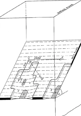
The gold-bearing conglomerates of the Witwatersrand system are essentially plane tabular in nature, implying a negligible height compared to the lateral extent of the orebody (Fig. 1). Although the reef is frequently dislocated by faults and dykes, the plane tabular nature of the orebody can persist for many square kilo- metres in some areas. Although the reef can be nearly horizontal in certain loca- tions, it is generally inclined between 25 and 45 (dip angle). The reef thickness can vary from a few centimetres to more than a metre. In order to maintain eco- nomic viability, the reefs are mined with as small a working height orstoping width as possible. In 1980 the average stoping width throughout the industry was esti-
Fig. 1.Schematic diagram of a typical tabular ore body dipping ata (after Salamon et al., 1964).
Visible are mined regions Cand areas of contact between the hangingwall and footwall B
mated to be 1.33 m (Gay and Jager, 1980). Reef extraction may extend over sev- eral square kilometres resulting in large stope spans and eventual contact between the roof (hangingwall) and ¯oor (footwall) of the excavations in the areas far from the working faces. The relative movement of the hangingwall and footwall normal to the plane of the reef is calledclosure.Convergencerefers to the elastic compo- nent of closure. Closure is therefore the sum of elastic convergence and inelastic deformation. The average rock breaking depth is approximately 2000 m, although workings deeper than 3500 m can be found (Schweizer and Johnson, 1997). It is forecast that by the year 2010 some 30% of South African gold production will come from depths greater than 3000 m (Johnson and Schweizer, 1996). Typical virgin stresses encountered at a depth of 2500 m are 70 MPa in the vertical direc- tion and 35 MPa in the horizontal direction.
A description of the most important gold-bearing reefs currently exploited can be found in Schweizer and Johnson (1997). The following two reef types are of interest in this study. The Ventersdorp Contact Reef (VCR) is an intermittent conglomerate at the base of the Ventersdorp Supergroup, with pebble sizes vary- ing from a few millimetres to 40 cm. The footwall of these excavations in di¨erent areas consists of a great variety of quartzites ranging from siliceous to argilla- ceous. The hangingwall of the VCR is formed by volcanic rocks that can be div- ided into Westonaria Formation lavas (termed soft lava) and Alberton Porphyry Formation lavas (termed hard lava). TheVaal Reefis a conglomerate consisting of small pebbles closely packed in a pyritic matrix. It varies in width from a car- bon parting to over 1.2 m. The footwall and hangingwall of the excavations in these areas consist of argillaceous to siliceous quartzites. The main rock types exposed by the tabular mining of these two reef types are therefore brittle quartzite and lava. The strength of these rocks varies greatly from area to area. The uniaxial (uncon®ned) compressive strength (UCS) of an average Witwatersrand quartzite is 200 MPa (Gay and Jager, 1980), although it can be as low as 130 MPa (Malan and Bosman, 1997). Some of the Alberton Porphyry lavas are very rigid and can have UCS values of more than 400 MPa. The laboratory creep rate of these quartzites and lavas are very low, as described in Malan (1998).
As a result of the great depth and the tabular nature of the excavations, large stresses are experienced ahead of the working faces. These normally exceed the strength of the rock, resulting in the formation of an extensive fracture zone.
Under high stress conditions, this zone can extend to more than 5 m ahead of the face (Adams et al., 1981). After blasting, the fracture zone needs to adapt to the changing stress conditions. Little is known about the time-dependent nature of this process. Adams and Jager (1980) investigated the extent of the fracture zone and the pattern of rock failure that occurs ahead of advancing stope faces. They found the formation of fractures to be associated with the face advance, with the major- ity of new fractures forming within a relatively short period after blasting. The amount of new fracturing taking place diminished with time. Their observations indicated that if the face was not mined for a period of two weeks, no new frac- tures formed. Turner (1984) also observed time-dependent fracture development at a mechanized rock-breaking site at Doornfontein Gold Mine. He investigated the occurrence of hard patches in the face that were therefore di½cult to mine using
126 D. F. Malan
mined for a month. The rock within 1.5 m of the face nevertheless experienced a further dilation of 10 mm in this period.
2. Time-dependent Closure Data
Time-dependent closure data of tabular excavations is a good re¯ection of the localised rock response and can provide important information which may be more di½cult to obtain with other methods. Unfortunately this source of data has been largely neglected in the South African industry. Although a large number of closure measurements have been recorded (Wiggill, 1965; GuÈrtunca, 1989; King et al., 1989; GuÈler, 1997), these measurements usually consisted of measure- ments with a 24 hour interval or longer between successive data points. Data col- lected by Walsh et al. (1977) at West Driefontein Mine had an interval of a week between measurements. All these measurements will be collectively termed long period measurements. Typical results obtained from these measurements can be very di½cult to interpret as the closure curves are the complex result of a) en- largement of the excavation, b) the face moving away from the measurement position and c) the true time-dependent behaviour of the rock mass. In spite of these problems, signi®cant time-dependent rock behaviour was noted by some researchers. Hodgson (1967) analysed data from East Rand Proprietary Mines and noted signi®cant time-dependent closure behaviour. He explained this behav- iour as being caused by the time-dependent migration of the fracture zone ahead of the face, resulting in the e¨ective stope span becoming bigger. King et al. (1989) measured closure behaviour in two adjacent panels at Hartebeestfontein Mine.
After blasting activity had stopped in one of the panels, the closure rate in this panel continued at a constant rate of 6 mm/day for 37 days. Only after this period did the rate gradually start to decrease. Mining, however, continued in the second panel (and probably in other nearby panels) and the e¨ect of these geometrical changes on the ®rst panel is unclear. After mining stopped in the second panel, the closure rate in this panel persisted for thirteen days and then gradually declined.
Closure data collected by GuÈrtunca (1989) in the Klerksdorp area, to quantify the e¨ect of back®ll, also exhibited signi®cant time-dependent e¨ects. Daily
closure rates varied from panel to panel and were in some instances as high as 30 mm/day.
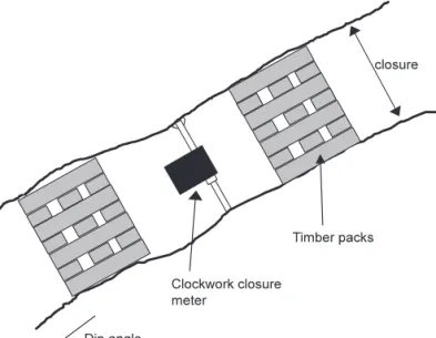
To analyse the true time-dependent behaviour of the rock mass, data for this study was collected using clockwork closure instruments which record the stope closure continuously. A description of these instruments can be found in Malan (1998). Figure 2 illustrates a typical installation of this instrument in a stope.
2.1 Closure Data of the Ventersdorp Contact Reef
Closure data was collected in the South Shaft area of Western Deep Levels Mine near Carletonville. The hangingwall of the Ventersdorp Contact Reef at this mine consists of hard lava. Some typical properties of the rocks in this area are given in Table 1. The general mining layout in this area is given in Fig. 3. The instrumen-
Fig. 2. Installation of the clockwork closure meter normal to the plane of the excavation
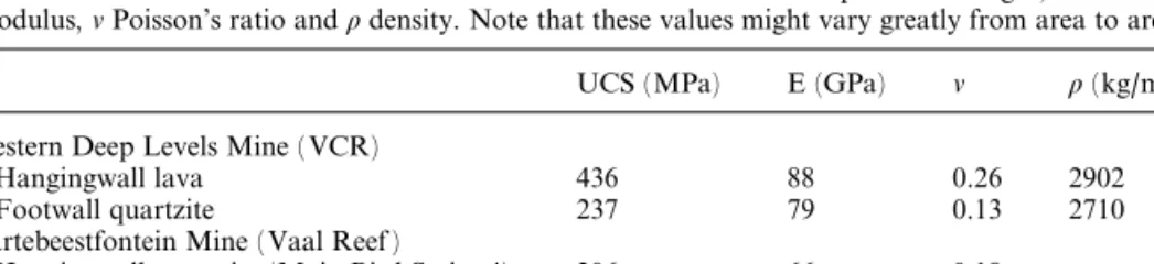
Table 1. Typical properties of the hangingwall and footwall rocks at Western Deep Levels Mine and Hartebeestfontein Mine. The abbreviations are:UCSUniaxial compressive strength,EYoung's modulus,nPoisson's ratio andrdensity. Note that these values might vary greatly from area to area
UCS (MPa) E (GPa) n r(kg/m3)
Western Deep Levels Mine (VCR)
Hangingwall lava 436 88 0.26 2902
Footwall quartzite 237 79 0.13 2710
Hartebeestfontein Mine (Vaal Reef )
Hangingwall quartzite (Main Bird Series 4) 206 66 0.18 ±
Footwall quartzite (Main Bird Series 5) 208 64 0.18 ±
128 D. F. Malan
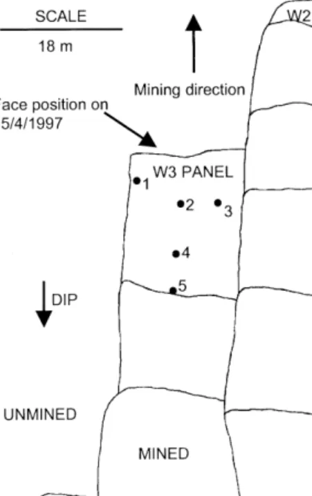
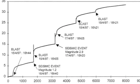
tation was installed in the W3 panel of the 87-49 longwall. An enlarged view of this panel is given in Fig. 4. The dip of the reef is 22and the depth below surface is approximately 2570 m. Timber packs are used as back-area support in this panel. Five clockwork closure meters were installed at any one time, with their positions before the blast on 15/4/97 illustrated in Fig. 4. Typical recorded time- dependent closure is illustrated in Fig. 5. Note that there is a sudden increase in the closure after the blast consisting of an instantaneous jump and a period (A5 hours) of decelerating rate of closure. This will be called the primary closure. This is followed by a more gradual steady-state closure rate. If there is no mining activity for a number of days, the rate of steady-state closure appears to remain constant in the short term (A48 hours after the last blast), but then gradually starts declining until the next blast occurs. Typically, after a period of two weeks with no blasting, the rate of steady-state closure is reduced to 10% of its short term value. Of interest is that if seismic events occurred close to the panel, time- dependent closure behaviour similar to that after a blast is observed as depicted in Fig. 5. The magnitude of the primary closure after a seismic event is dependent on the magnitude of the event and how close its source was located to the panel. A further closure data set is given in Fig. 6.
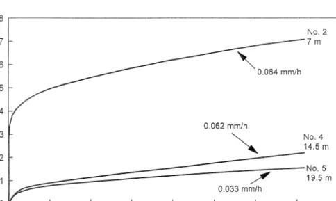
After any particular blast, the increase in closure is a function of the distance to the face, position in the panel and length of face advance. Fig. 7 illustrates the incremental closure for stations no. 2, 4 and 5 (see Fig. 4) after the blast on 15/4/
97. The primary closure is large close to the face, but smaller as the distance to the
Fig. 3.Plan view of the mining geometry in the area where the closure data was collected at Western Deep Levels Mine
Fig. 4. Enlarged plan view of the W3 up-dip panel in the 87-49 longwall with the positions of the clo- sure meters indicated
Fig. 5. Typical time-dependent stope closure of the Ventersdorp Contact Reef at Western Deep Levels Mine. This was for a closure station at a distance of 8.7 m from the face
130 D. F. Malan
face increases. The rate of steady-state closure also decreases into the back area.
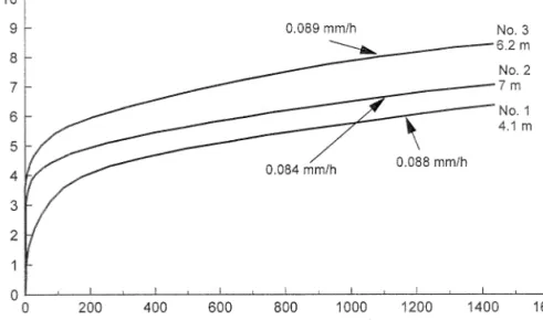
Figure 8 compares the behaviour after the same blast for the row of stations ap- proximately parallel to the face (no. 1, 2 and 3). Although the steady-state closure rate is essentially similar for these three stations, the magnitude of primary closure
Fig. 6. Time-dependent closure measured at Western Deep Levels Mine. This was for instrument no. 1 which was 4.1 m from the face before the blast on 15/4/97. The overshoot behaviour after seismic events is a response of the closure meter due to dynamic loading and not a re¯ection of the true rock
mass behaviour
Fig. 7. Closure as a function of time for di¨erent positions in the panel following the blast on 15/4/97.
The distances given in the graph are the distances from the closure instruments to the face before the blast (see Fig. 4)
increases from the solid abutment (no. 1) to the previously mined side (no. 3) of the panel. As it is di½cult to determine the onset of the steady-state closure phase, the closure rates given in Fig. 7 and Fig. 8 were calculated for a period from 600 minutes after the blast to the end of the data set. The dependence of the rate of steady-state closure on distance to face is further illustrated in Fig. 24 (Section 4).
Note that this behaviour is only noted in Ventersdorp Contact Reef stopes where the hangingwall consists of hard lava (see Section 1.2 for a description of hard and soft lava). In areas where the lava is soft, measurements (not described in this study) indicate that the steady-state closure rate is much higher and the behaviour is more similar to the Vaal Reef described below. Note that any further reference to the behaviour of Ventersdorp Contact Reef stopes in this paper refers to those areas where the hangingwall consists of hard lava.
2.2 Closure Data of the Vaal Reef
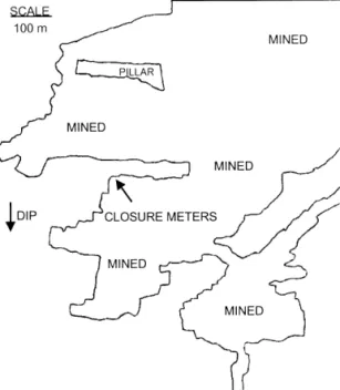
To contrast the relatively low closure rates of the Ventersdorp Contact Reef with areas experiencing signi®cant closure, data was collected from the No. 6 shaft pillar area at Hartebeestfontein Mine in the Klerksdorp area. Some typical prop- erties of the rocks in this area are given in Table 1. A schematic diagram of the shaft pillar area is given in Fig. 9. A single closure meter was installed in the po- sition illustrated in Fig. 10. The dip in this area was 7 and the depth approxi- mately 2350 m. Timber packs were used as back-area support in this panel. This shaft area is known to have very high closure rates. Of signi®cance are the well- de®ned bedding planes in the quartzite. The nature of in®lling of these dis-
Fig. 8. Closure as a function of time for di¨erent positions approximately parallel to the face following the blast on 15/4/97. The distances given in the graph are the distances from the closure instruments to
the face before the blast (see Fig. 4)
132 D. F. Malan
continuities makes conditions less favourable for stable mining excavations. The overall competency of the rock mass and its ability to provide stable mining excavations for prolonged periods appears to be less favourable than the rock types encountered in Ventersdorp Contact Reef mining operations. The quartzites of the Ventersdorp Contact Reef appear to be less bedded and substantially more siliceous than those present at Hartebeestfontein Mine. As a result of this greater strength, the rock in other mines would appear to be more susceptible to strain bursting under high stress conditions.
A typical time-dependent closure pro®le is given in Fig. 11. Evident is the high steady-state closure rate compared to that of the Ventersdorp Contact Reef, while the instantaneous closure at the time of blasting is small. A second data set is given
Fig. 9. Plan view of the mining geometry at No. 6 shaft pillar area, Hartebeestfontein Mine, where the closure data was collected.
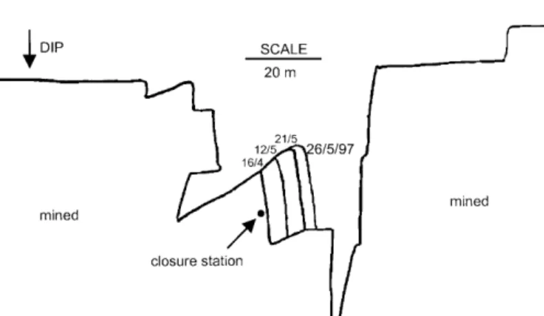
Fig. 10. Location of the clockwork closure instrument in the 78N23 longwall at No. 6 shaft, Harte- beestfontein Mine
in Fig. 12. Note that the rate of steady-state closure increased as the instrument moved further away from the face. This is unlike measurements taken in the Ventersdorp Contact Reef stopes. A signi®cant di¨erence in the geotechnical properties of this area, compared to the Ventersdorp Contact Reef, is the presence of well-de®ned bedding planes. It appears that slip and dilation of these bedding
Fig. 11. Closure measured at Hartebeestfontein Mine. The instrument was 10.9 m from the face before the blast on 19/5/97. The steady-state closure rates were calculated for the periods from approximately
600 minutes after the blast until the next blast occurred
Fig. 12.Closure measurements at Hartebeestfontein Mine for a larger distance to face than that in Fig.
11. The instrument was 14.2 m from the face before the blast on 26/5/97
134 D. F. Malan
planes is an important mechanism controlling the closure behaviour. This, coupled with the rapid deterioration of the hangingwall due to time-dependent fracture processes, may explain the increase in steady-state closure rates for larger dis- tances from the face. Control of the hangingwall strata is di½cult and these areas might be prone to falls of ground.
3. Modelling the Time-dependent Stope Behaviour
Linear viscoelastic theory is commonly used to simulate the time-dependent behaviour of rock. Although it is not possible to simulate rock failure and inelastic movements, even recent publications can be found where this theory is used (Pan and Dong, 1991; Yang et al., 1996). Malan (1998), however, found that there are some subtle problems associated with the use of viscoelastic theory to simulate the time-dependent behaviour of tabular excavations in hard rock. These problems arise from the special tabular geometry of the excavations and are not readily apparent when applying the theory to circular tunnels. From the discussion in Section 1, it is evident that the time-dependent failure processes in the rock play a prominent role in the time-dependent behaviour of these tabular excavations. It appears as if the signi®cant time-dependent e¨ects are con®ned to the fracture envelope surrounding the tabular excavations. The far ®eld rock mass behaviour has been shown to be adequately represented by elastic theory (Ryder and O½cer, 1964). An idealisation of this concept is given in Fig. 13. Note that the actual shape of the fracture envelope is not necessarily as depicted in the ®gure.
To include failure processes in rheological models, slider elements (also called St. Venant elements) are typically added to the elastic and viscous elements of viscoelasticity. These slider elements have a speci®ed failure strength and are immobilised below this strength. Commonly, a viscous element is placed in paral- lel with the slider to control the strain rate if the slider is loaded above its failure strength. This is the so-called Bingham unit. Various combinations of elastic, vis-
Fig. 13. Conceptualization of the fracture zone surrounding tabular excavations (section view) and time-dependent extension of this zone following a mining increment. The coordinate system is similar to
that in Fig. 1, with the y-direction out of the plane of the page
cous and St. Venant elements have been used by researchers to simulate particular time-dependent problems. Gioda (1982) and Gioda and Cividini (1996) used a Kelvin viscoelastic model in series with a Bingham unit to represent primary and secondary closure in squeezing tunnels. Tertiary movements can be considered by providing suitable laws relating the values of the mechanical parameters (such as viscosity) to the irreversible part of the time-dependent strain. These rheological models are particularly suited for implementation in the ®nite element method.
Other examples of the use of these rheological models can be found in Akagi et al.
(1984), Song (1993), Lee et al. (1995), Euverte et al. (1994) and Sagawa et al.
(1995).
Nawrocki (1995) developed a one-dimensional semi-analytical solution for the time-dependent behaviour of a coal seam. A Bingham type of material model was assumed. This study was initiated to investigate the rate of face advance on rock- burst occurrence. The analysis showed that rapid ore extraction produces zones of high stress concentrations close to the longwall face. This situation is deemed to be hazardous as it increases the likelihood of rockbursting.
Since Perzyna (1966) proposed the general concept of elasto-viscoplasticity, a number of workers have applied this theory to geological materials. Elasto-visco- plasticity is essentially a modi®cation of classical plasticity theory through the in- troduction of a time-rate rule in which the yield function and plastic potential function of classical plasticity are incorporated. In comparison with viscoelasticy, a viscoplastic material shows viscous behaviour in the plastic region only. Desai and Zhang (1987) used this theory together with a generalised yield function to characterise the viscoplastic behaviour of sand and rock salt. Sepehr and Stimpson (1988) used Perzyna's theory as a basis to develop a time-dependent ®nite element model to understand the time-dependent closure of excavations and seismicity in the potash mines in Saskatchewan. For a rheological analysis of tunnel excava- tions, Swoboda et al. (1987) developed a coupled ®nite element/boundary element approach to analyse the interaction of the rock with the viscoelastic properties of the shotcrete. The rock was assumed to behave in an elasto-viscoplastic fashion.
Fakhimi (1992) and Fakhimi and Fairhurst (1994) proposed a visco- elastoplastic constitutive model to simulate the time-dependent behaviour of rock.
The model consists of an elasto-plastic Mohr-Coulomb model in series with a lin- ear viscous unit. This model was implemented in an explicit ®nite di¨erence code.
A typical solution cycle would be to do an elasto-plastic analysis, during which real time is frozen. After an equilibrium point is reached, the linear viscous unit is used to determine additional creep strain components for a speci®ed period of real time. Control is then passed back to the elasto-plastic analysis to obtain a new equilibrium and the process is repeated. Although this model appeared successful in imitating the behaviour of uniaxial and triaxial tests and the stand-up time of excavations, the time dependent behaviour of the model is independent of the failure processes. The entire material (including the far ®eld) also behaves in a viscous manner. This model is therefore not applicable to the conceptual model of deep excavations in hard rock (Fig. 13), where the time-dependency is a direct consequence of the failure processes and the solid rock behaves essentially elastically.
136 D. F. Malan
3.1 Elasto-Viscoplastic Formulation
For this study, classical elasto-viscoplasticity as de®ned by Perzyna (1966) is used as a basis for the formulation. Figure 14 shows the rheological analogue of the developed model. The strength of the slider is controlled by a novel time- dependent weakening rule as described below. Similarly to elasto-plastic theory, the concepts of yield function and ¯ow rule also apply. However, in viscoplasticity theory, stresses above the yield surface are permissible.
Yield Surface
A time-dependent Mohr-Coulomb shear yield function is assumed and is given by fs t s1ÿs3Nfc2Cc
Nfc
p 1
and
Nfc1sinfc
1ÿsinfc; 2
where fc is the current value of friction angle, Cc is the current value of cohe- sion,s1 is the major principle stress ands1<s2<s3 for a convention of nega- tive compressive stresses. Equation (1) is a function of time t owing to a time- dependent reduction in the value of the cohesionCc once the rock fails. This is explained below.
Shear failure takes place for fs tU0. For fs t>0, the rock behaves elasti- cally. The cohesionCcand friction anglefcwill assume peak valuesCpandfpfor intact rock. Therefore the shear yield function fs tis not a function of time for intact rock. For intact rock, Eq. (2) becomes
Nfp1sinfp
1ÿsinfp: 3
Once the particular volume of rock starts failing, the friction angle assumes a residual valuefr and the cohesion gradually decays to a residual valueCr. This cohesion softening process is simulated as a time-dependent process which is described later. This is also depicted in Fig. 15. It should be noted that the model can be easily extended to also allow for a time-dependent variation in the value of friction angle. For the modelling of non-linear rock failure behaviour, strain soft- ening constitutive models are often used where both cohesion and friction varies with plastic strain (but not with time). The failure of Lac du Bonnet granite in laboratory compression tests (Martin, 1997) can be used as an example of the behaviour of hard rock. As the rock becomes damaged due to increasing strain, a portion of its cohesive strength is lost and friction is mobilized to its peak value.
For small amounts of damage, the cohesion loss is rapid and can amount to 50%
or more of the initial cohesion. The friction attains a peak value for small amounts of damage and then gradually decreases with increasing damage. From work done by Martin (1997) in the Underground Research Laboratory in Manitoba, Canada, it appears that at low con®ning stresses, such as those which occur in the near ®eld rock mass around underground openings, the brittle-failure process in hard rock is dominated by cohesion loss. When developing the constitutive law in Eq. (1) for this current study, it was therefore assumed that the cohesion softening plays a dominant role in the time-dependent behaviour. For simplicity, the reduction in friction angle is assumed to be independent of time. For the numerical examples in Sections 3.2 and 4, this is irrelevant as it was assumed thatfp fr.
Fig. 15. The evolution of the yield surface for intact rock to the eventual residual surface for failed rock. Note that compressive stresses are negative and that on the vertical axis the negative of the major principal stress is plotted to turn the ®gure upright.Nfris de®ned in Eq. (10).TCis the tensile strength
of intact rock
138 D. F. Malan
potential function is given by
gss1ÿs3Nc2Cc
Nc
p 6
with
Nc1sinc
1ÿsinc 7
andcis the dilation angle. From Eq. (4) it follows that in the model the strain rate of the failed rock is proportional to the excess stress above the yield surface.
Time-dependent Strength
A constitutive description of time-dependent rock behaviour should include the e¨ect of strength degradation with time and/or deformation. Experimental evi- dence (Kranz et al., 1982) indicated that rock under load shows a decrease in strength with time. Fakhimi and Fairhurst (1994) modelled the time-dependent degradation of material strength by exponential friction and cohesion decay functions. Aydan et al. (1996) simulated the time-dependent behaviour of squeez- ing rocks as the degradation of strength properties as a function of time by utilis- ing information obtained from creep tests.
Observations of time-dependent fracturing ahead of tabular stopes and in some haulages in the South African gold mines show that the rock becomes progres- sively more fractured with time, resulting in the gradual loss of cohesive strength in a particular volume of rock. This loss of strength will be modelled by assuming that the rate of cohesion reduction is proportional to the excess stress above the residual target surface (also see Eqs. (I.11) and (I.12) in Appendix I)
C_ckchfresi; 8
wherekcis the cohesion decay factor and
fress1ÿs3Nfr2Cr
Nfr
p 9
Nfr1sinfr
1ÿsinfr 10
is the residual target surface. The principle embodied in Eq. (8) is based on labo- ratory observations (Malan, 1998) that if rock specimens are loaded close to the uniaxial strength, the creep rate and eventual creep failure occur faster than for a low stress. For a particular volume of rock under high stress, creep fractures will therefore form more rapidly, resulting in a faster loss of cohesion in the rock than for low stress.
The model developed above was implemented in a creep version of the com- puter program FLAC (Itasca, 1993) using the built-in FISH language. Any other suitable ®nite di¨erence or ®nite element code could, however, be used. FLAC is an explicit ®nite di¨erence code developed for geotechnical engineering applica- tions. The two-dimensional version of the code was used in this study. FISH is a programming language embedded within FLAC, enabling the user to de®ne new variables, functions and constitutive models. The creep version of FLAC gives access and control over a timestep that represents real time. Appendix I gives some detail regarding this implementation in FLAC.
3.2 Simulating the Closure Behaviour of Tabular Excavations
Malan and Bosman (1997) used the model described above to succesfully simulate the time-dependent increase in the extent of the fracture zone around squeezing tunnels. Soon after development of the tunnel, the failed zone covered those areas where the stresses exceeded the failure strength of the intact rock fs tU0.
Time-dependent processes lead to a gradual loss of residual strength in the frac- tured rock, transferring stress to the unfailed rock. This then also becomes frac- tured, resulting in a time-dependent increase in the extent of the fracture zone.
Depending on the chosen model properties, an equilibrium position is eventually reached with no further growth in the fracture zone.
To investigate the applicability of the model for simulating time-dependent stope closure, the incremental mining of a panel was investigated. Figure 16 illus- trates the geometry used. The size of the ®nite di¨erence mesh was 10080 ele- ments, appropriately graded to ensure that the boundaries were su½ciently far away from the stope. The size of the elements in the area of the stope was 0.2 m, while the size of each mining increment was 1 m. Quarter symmetry was used to save on the number of elements. The stoping width was 1.2 m, although only 0.6 m is shown in Fig. 16 due to the imposed symmetry. Note the direction of the vertical sv and horizontal sh stress on the boundary of the model in Fig. 16. When applying the shear failure criteria in Eq. (1), the major s1and minor s3prin- cipal stresses need to be determined. The out-of-plane stress is taken as a principal stress with three di¨erent cases recognised. The out-of-plane stress is either (1) the major principal stress, (2) the minor principal stress or (3) the intermediate prin- cipal stress. The Cartesian stress components (horizontal, vertical and out-of-plane stresses) are resolved into principal stresses and ordered so thats1<s2<s3. The directions of the two in-plane principal stresses vary with position around the stope. Typical magnitudes and directions of these principal stresses around tabular stopes can be seen in Napier (1990). Although the model appeared successful in
140 D. F. Malan
replicating the closure behaviour as explained below, very large computer run- times were recorded. The explicit solution scheme of FLAC requires a small timestep to ensure stability. Following a large instantaneous stress change (for example after a mining increment), the timestep must be very small. Only as a new equilibrium state is approached, can the timestep be progressively enlarged. The run-time for ten mining increments in the simulation of Fig. 16 with weak rock properties can easily exceed 72 hours on a 200 MHz Pentium computer. This cur- rently prohibits the simulation and calibration of incremental stope behaviour if the span is large. For the illustrative stope problems in Section 4, a low number of mining increments was used with high ®eld stresses to obtain the required high stresses ahead of the face.
To investigate the simulated closure behaviour of a tabular excavation, eight increments were mined (giving a total span of 16 m), using the properties given in Table 2. Typical closure results are given in Fig. 17 as a function of time after mining the 8thincrement. For the two distances from the face, behaviour similar to that noted for the experimental results of the Ventersdorp Contact Reef is obtained. The incremental jump after blasting is reduced as the distance to face increases. Furthermore, the closure rate of the steady-state phase also decreases into the back area. These results are encouraging as this behaviour cannot be simulated with a viscoelastic model, as explained in Malan (1998). The visco- plastic model approximates the time-dependent failure processes and therefore gives the correct closure response for the Ventersdorp Contact Reef. No attempt was made to simulate the Vaal Reef as the behaviour of this reef is dominated by the bedding plane movements. The ®nite di¨erence mesh is not suitable for the
Fig. 16.Geometry and boundary conditions used for simulating tabular excavations (not drawn to scale)
inclusion of multiple discontinuities to simulate these parallel bedding planes. To simulate the time-dependent behaviour within an assembly of explicit dis- continuities, Napier and Malan (1997) developed a discontinuum viscoplastic model suitable for implementation in a boundary element code.
In the example above, arbitrary model parameters were used to illustrate the closure pro®les. Due to the success of this model in simulating the time-dependent fracture process, it is desirable to calibrate these parameters using underground closure data. The two-dimensional plain strain version of FLAC was used and therefore only geometries, where these assumptions can be made, are appropriate.
As the results obtained from viscoplasticity theory are path dependent, the entire
Table 2. Properties used for the incremental mining of the tabular stope to obtain the results in Fig. 17
Parameter Value
Vertical stress,sv 60 MPa
Horizontal stress,sh 30 MPa
Bulk modulus,K 38.9 GPa
Shear modulus,G 29.2 GPa
Density of the rock,r 2700 kg/m3
Cohesion of intact rock,CP 22 MPa
Friction angle (Both peak,fP, and residual,fR) 30
Residual cohesion,Cr 10 MPa
Cohesion decay,kC 0.005 hÿ1
Dilation angle,c 0
Fluidity coe½cient,m 110ÿ10Paÿ1:hÿ1
Fig. 17. Simulated time-dependent closure. The distances were the original distance to face before mining the increment. The steady-state closure rate was calculated between 2 hours and the end of the data set. Note that although only the ®rst 7 hours after the mining increment is plotted, the time period
between each step was 24 hours
142 D. F. Malan
stope span cannot be simulated in one mining increment. Data was therefore needed where the span of the stope was small. Closure data collected by Kersten (1995) at Hartebeestfontein Mine in 1965 was used. The geometry was such that a two-dimensional plane strain approximation could be made. The instrumented panel was situated at a depth of 1850 m, with a span of 20 m. The actual stress conditions and rock parameters are not known accurately and therefore the ob- jective of this simulation was not exact parameter calibration, but an attempt to replicate the observed pro®les. The closure ®tting process was very arduous as ten mining increments (using symmetry) had to be mined. It was found that the path dependence and slow run times made it very di½cult to achieve the desired ®nal closure by making small changes in the parameter values before the ®rst incre- ment. In spite of these problems, it should be noted that the closure behaviour of the viscoplastic model gives similar trends to that of the underground measure- ments. Figure 18 shows the experimental data and numerical results for a ¯u- idity coe½cient of 110ÿ10Paÿ1hÿ1 and a cohesion decay rate of 0.005 hÿ1. Other parameters used were bulk modulus38:8 GPa, shear modulus29 GPa, cohesion22 MPa, residual cohesion15 MPa and friction angle (peak and residual)30. In the model, the stope was mined incrementally to the required span, using 1 m increments.
4. The Use of Closure Data as a Diagnostic Measure of Rock Mass Behaviour When comparing typical results of the Vaal Reef in Fig. 11 with those of the Ventersdorp Contact Reef in Fig. 5, it is clear that signi®cant di¨erences exist between the continuous closure pro®les of these di¨erent geotechnical areas. For a more direct comparison, typical closure increments after blasts for these two areas
Fig. 18. Experimental and simulated stope closure after blasting
are plotted in Fig. 19. The two experimental sites are approximately at the same depth and, for these speci®c data sets, the closure instruments were approximately the same distance from the face. Although care should be taken when comparing these sites directly, owing to di¨erent mining geometries, the following important di¨erences are noted. The closure behaviour of the Ventersdorp Contact Reef (hard lava) is characterised by a large instantaneous jump after blasting followed by a low closure rate. These areas appear to be prone to face bursting. In contrast, for the Vaal Reef, the closure is characterised by a small instantaneous jump after blasting followed by a high rate of closure. The risk of face bursting is low in these areas, although the risk of falls of ground is more pronounced.
The instantaneous jump in closure after blasting is the result of the immediate redistribution of stress following the removal of an increment of rock in the face.
The more signi®cant the disturbance to the stress ®eld, the more pronounced the immediate response will be. If the increment of rock removed by blasting carries no load (in essence loose rock lying at the face) no change in the stress ®eld will take place and no change will be noticed in the closure behaviour. The instanta- neous closure response after blasting therefore appears to indicate the role the removed rock played in maintaining the stress equilibrium before the blast. For the Ventersdorp Contact Reef, the signi®cant instantaneous closure after blasting is probably an indicator of a more highly stressed face area than the Vaal Reef.
This may explain why face bursting appears to be more pronounced on this reef than the Vaal Reef.
A further di¨erence in behaviour between these areas is the high rate of steady- state closure of the Vaal Reef stopes compared to the Ventersdorp Contact Reef (hard lava) stopes. The high steady-state closure rate is an indication of e½cient stress redistribution through mobilization and growth of the fracture zone and slip
Fig. 19.Comparison of typical closure pro®les of the Ventersdorp Contact Reef (hard lava) and Vaal Reef. For the Vaal Reef measurements the instrument was 11.5 m from the face before the blast while it
was 10 m from the face for the Ventersdorp Contact Reef measurements
144 D. F. Malan
on discontinuities, such as bedding planes. This in turn may result in low face stresses. Although the face bursting hazard might be low in areas with high steady- state closure rates, the large time-dependent behaviour of the fracture zone might lead to a rapid deterioration of hangingwall, thereby increasing the fall of ground hazard.
It was suggested above that the instantaneous closure after blasting is an indi- cation of the proximity of the stress peak to the face. This hypothesis was tested by simulating two stopes (A and B), using the viscoplastic model described above.
The parameters used are given in Table 3. The only di¨erence between these stopes is a di¨erent rate of cohesion decay. This resulted in the rock ahead of the face of Stope B losing its strength much faster than the rock ahead of Stope A, therefore carrying less load. This is illustrated in Fig. 20, where the major principle stress is plotted against distance ahead of the original face position just before an increment is mined. Visible in this ®gure is the stress peak for both stopes some distance ahead of the face. With su½cient distance from the face, the stress mag- nitude is reduced to the virgin value. For Stope A the peak is closer to the face.
The next increment of mining will remove the ®rst metre of rock thereby forcing the stress carried by this increment to be instantaneously redistributed. As the average stress in this increment of rock is larger for Stope A than Stope B, it is expected that the instantaneous closure will be bigger for A. This is con®rmed by the closure that followed this increment in Fig. 21. For Stope A the instantaneous closure was 3.7 mm, compared to the 2.5 mm for Stope B. Following the instan- taneous closure, the steady-state closure for Stope B is larger as the failed rock loses its strength faster, resulting in greater time-dependent deformation.
Figure 20 illustrates the position of the peak stress 24 hours after mining an increment. This position is not stationary but moves as the time-dependent frac- ture processes occur in the rock. To illustrate this, Fig. 22 illustrates the stress peak for various times after mining the particular increment of Stope B. Soon after the blast the peak is high and located close to the face. With time it moves away, due to the fracture processes, gradually becoming smaller. Of signi®cance is that the
Dilation angle,c 15
Fluidity coe½cient,m 110ÿ10Paÿ1:hÿ1
biggest stress change happens within the ®rst ®ve hours. This is also the approxi- mate duration of the primary closure phase for stope B in Fig. 21.
It appears then that the instantaneous closure observed underground might be used as an indication of the stress magnitude in the face area and, therefore, also an indicator of the face bursting hazard. It should, however, be emphasised that the instantaneous closure response after a blast is a re¯ection of the face stress
Fig. 20. Major principal stress as a function of distance ahead of the face for the two simulated stopes.
These stresses were calculated in the centre of the reef
Fig. 21. Comparison of the simulated closure behaviour as a function of time after the blast. The measurement position was 0.5 m behind the original face
146 D. F. Malan
before the blast and not after it. Underground measurements (Fig. 25) indicate that the instantaneous closure appears to include a random component and is therefore not deterministic. This random component might be caused by the varying rock properties (and therefore varying stress magnitudes) ahead of the face, although mining technique and measurement position also play a strong role.
If only a portion of the face is blasted and not the entire length, the instantaneous closure at a particular measurement position will be smaller. The uninformed ob- server might then be deceived into concluding that the face stress is dropping. Due to these factors, prediction of face bursting would be very di½cult if not impossi- ble. The value of these closure measurements should rather be seen as the possible identi®cation of hazardous areas. An average value of instantaneous closure taken over a speci®ed period might be useful to de®ne a face bursting risk. This can be seen from the data collected underground where the average instantaneous closure of the Ventersdorp Contact Reef (hard lava) is clearly much higher than that of the Vaal Reef.
4.1 The E¨ect of Preconditioning on Time-dependent Closure Behaviour Preconditioning is a technique used in the South African gold mining industry to
``engineer'' the fracture zone ahead of advancing mining faces. Large stresses are occasionally present in the fracture zone close to the face because of interlocking discontinuities or low fracture densities. This can result in sudden stress release through face bursting. Preconditioning is used in these areas to help sustain the normal development of the fracture zone and push the stress peak further ahead of the face. The technique consists of drilling long holes, either parallel or perpen-
Fig. 22. Simulated time-dependent movement of the major principal stress peak ahead of the face after blasting due to the migration of the fracture zone
dicular to the face. The perpendicular holes (used at Western Deep Levels Mine) are typically 2.4 m deep and are blasted as part of the production sequence. Kull- mann et al. (1996) reported that these preconditioning blasts did indeed achieve the desired objectives.
Preconditioning was not used in the stopes described in Section 2 of this paper.
The closure data presented therefore does not include the e¨ect of preconditioning.
Since collection of this data, preconditioning was introduced in the 87-49 longwall at Western Deep Levels Mine. Measurements were taken in a panel not far from those depicted in Fig. 4. Typical results are illustrated in Fig. 23. Note that the steady-state closure rate increases signi®cantly after the onset of preconditioning.
This is further illustrated in Fig. 24, which compares the rate of steady state closure as a function of distance from the face for panels with and without precondition- ing. These rates were calculated for 10 hours to approximately 24 hours after each blast. It is clear from this that the steady-state creep rate is signi®cantly increased with preconditioning. This is probably an indication of enhanced time-dependent deformation of the rock mass that reduces the amount of strain energy stored close to the face and therefore also the likelihood of face bursting.
It is not clear at this stage what the e¨ect of preconditioning is on the instan- taneous closure response after blasting. In Fig. 23, the instantaneous response after the ®rst preconditioning blast was signi®cantly higher than the previous blasts.
This might be the result of the 2.4 m deep preconditioning blasts a¨ecting a larger volume of stressed rock, compared to ordinary production blasting. Figure 25 compares the instantaneous closure after blasting with and without precondition- ing. Note that there is not a distinct di¨erence for the two cases, although the values for the preconditioning appear to be slightly higher. Also note that there appears to be a poor correlation between magnitude of instantaneous closure and
Fig. 23.The e¨ect of preconditioning on the time-dependent closure of a stope in the Ventersdorp Contact Reef. The values indicated in the ®gure are the steady-state closure rates and were calculated for the periods of 800 minutes after the blast until the next blast occurred. The instrument was 7.2 m from the face at the beginning of this data set and 10.5 m from the face after the last blast in the ®gure
148 D. F. Malan
distance to face. One factor causing this is the position of the closure instrument in the direction parallel to the face. This geometrical e¨ect is illustrated in Fig. 8. The length of face advance for the particular blast and whether the entire face or only a portion is blasted, also plays a role. For a ®xed position in the direction parallel to the face, it is found that the instantaneous closure typically reduces in magnitude as the distance to the face, increases. This can be seen in Fig. 6 and Fig. 7.
Fig. 24. The e¨ect of preconditioning on the rate of steady-state closure for panels in the Ventersdorp Contact Reef
Fig. 25. The e¨ect of preconditioning on the instantaneous closure after blasting of the Ventersdorp Contact Reef
5. Conclusions
Although excavations in hard rock are not usually perceived to undergo signi®cant time-dependent deformation owing to the low creep rate of intact rock, data from the deep gold mines in South Africa illustrates behaviour to the contrary. Closure measurements in the tabular excavations indicate signi®cant time-dependent deformation. Although the excavations are developed in brittle quartzite and lava, the rate of steady-state closure can be as high as 0.7 mm/h in certain areas. The closure behaviour of these excavations typically consists of an instantaneous response at blasting time, followed by a primary phase of decelerating closure, lasting approximately ®ve hours, and a steady-state closure phase. This pattern is repeated after the next blast. This time-dependent closure behaviour is the result of the rheological behaviour of the fracture zone that surrounds these excavations.
After a mining increment, the fracture zone extends in a time-dependent fashion ahead of the working faces. The majority of new fractures appear to form within approximately the ®rst ®ve hours after the blast. Thereafter, the number of new fractures decreases until the next blast occurs.
For tabular excavations in the Ventersdorp Contact Reef (hard lava), the in- stantaneous closure response is very prominent, but decreases in magnitude as the distance from the face to the measurement position increases. The steady-state closure rate also decreases in magnitude with distance to the face. In contrast, for excavations in certain areas of the Vaal Reef, the steady-state closure rate can be as high as 15 mm/day. For these excavations the instantaneous closure response at blasting time is virtually absent. Unlike the Ventersdorp Contact Reef, the steady- state closure rate of the experimental panel in the Vaal Reef increases with increasing distance to the face. This di¨erence in behaviour is caused by the pres- ence of prominent bedding planes in the hangingwall of the Vaal Reef.
To allow for direct simulation of the time-dependent fracture zone behaviour, a continuum viscoplastic model was developed. The model is based on classical viscoplasticity, with a novel time-dependent cohesion weakening rule to simulate the time-dependent failure of the rock. A Mohr-Coulomb failure law and a non- associated ¯ow-rule were assumed. For an excavation in this material, the failure zone, soon after development, covers those areas where the stress exceeded the failure strength of the rock. The time-dependent processes lead to a gradual transfer of stress to the unfailed rock. This also becomes fractured, leading to a time-dependent growth of the fracture zone. The process continues until an equi- librium position is attained. This model has proved to be successful in simulating the time-dependent closure behaviour of tabular excavations, giving both the in- stantaneous response at blasting time and the primary and steady-state closure phases.
An important ®nding of this study is that the time-dependent closure data can possibly be used to deduce important information about the behaviour of the rock mass and the stress in the fracture zone ahead of the face. Although estimation of absolute stresses may not be feasible, the closure may be used to identify areas with large average face stresses and therefore an increase in the risk of face burst- ing. It appears that the instantaneous closure response at blasting time gives an
150 D. F. Malan
further.
Acknowledgements
This work forms part of the rockmass behaviour research programme of Rock Engineering, CSIR Division of Mining Technology. The ®nancial assistance and support received from the Safety in Mines Research Advisory Committee (SIMRAC) is acknowledged. The au- thor recently completed a Ph.D degree at the University of the Witwatersrand and the work described here also formed part of that study. The personnel of the Rock Mechanics Departments at Hartebeestfontein Mine and Western Deep Levels Mine, South Shaft, are thanked for their assistance in providing panels for the experimental closure measurements.
Dr. John Napier, Mr. Van Zyl Brink and Mr. Mike Roberts reviewed the manuscript and improved the quality of the work with their helpful comments.
Appendix I. Implementation of the Elasto-Viscoplastic Model in FLAC When a new constitutive model is written for FLAC, using the built-in language FISH, the main task is to update the stress tensor in each timestep for the given old stress tensor and strain components at the start of the timestep (Itasca, 1993).
For the viscoplastic model developed in Section 3, the rock behaves elastically if the failure strength is not exceeded. During each cycle in the program stepping, each element is tested for failure using Eq. (1). For elements that have not failed, CcCp andfcfp. Once the element fails,fc is set tofrwhileCcis gradually reduced fromCptoCras explained below.
For elements where the stress exceeds the failure strength, the total strain increment is given by
DeiDeieDeivp fori1;2;3: I.1
Writing Eq. (4) in incremental form gives DeivpmDthfs tiqgs
qsi fori1;2;3; I.2
whereDtis the timestep. Inserting Eq. (6) in Eq. (I.2) and then in Eq. (I.1) gives
De1De1emDthfs ti;
De2De2e;
De3De3eÿmDthfs tiNc:
I.3
The stress increments si0ÿsi0 are related to the elastic strain increments by the elasticity equations
s10 s10ADe1eB De2eDe3e;
s20 s20ADe2eB De1eDe3e;
s30 s30ADe3eB De1eDe2e;
I.4
where
AK4G
3 ; I.5
BKÿ2G
3 : I.6
Kis the bulk modulus andGthe shear modulus of the rock. The initial estimate of new stresses (before testing for failure) is also derived from the elasticity relations
s1I s10ADe1B De2De3;
s2I s20ADe2B De1De3;
s3I s30ADe3B De1De2:
I.7
This can be written as
s10s1IÿADe1ÿB De2De3;
s20s2IÿADe2ÿB De1De3;
s30s3IÿADe3ÿB De1De2:
I.8
When inserting Eq. (I.3) this gives
s01s1IÿADe1emDthfs ti ÿBDe2eDe3eÿmDthfs tiNc;
s02s2IÿADe2eÿBDe1eDe3emDthfs ti 1ÿNc;
s03s3IÿADe3eÿmDthfs tiNc ÿBDe1eDe2emDthfs ti:
I.9
This in turn can be inserted in Eq. (I.4) to give
s10 s1IÿmDthfs tiAÿBNc;
s20 s2IÿBmDthfs ti1ÿNc;
s30 s3IÿmDthfs tiBÿANc:
I.10
152 D. F. Malan
References
Adams, G. R., Jager, A. J. (1980): Petroscopic observations of rock fracturing ahead of stope faces in deep-level gold mines. J. S. Afr. Inst. Min. Metall. 44, 204±209.
Adams, G. R., Jager, A. J., Roering, C. (1981): Investigations of rock fracture around deep level gold mine stopes. In: Einstein, H. H. (ed.) Proc., 22nd U.S. Symp. Rock Mech., 213±218.
Akagi, T., Ichikawa, Y., Kuroda, H., Kawamoto, T. (1984): A non-linear rheological analysis of deeply located tunnels. Int. J. Num. Anal. Meth. Geomech. 8, 457±471.
Aydan, OÈ., Akagi, T., Kawamoto, T. (1996): The squeezing potential of rock around tun- nels: Theory and prediction with examples taken from Japan. Rock Mech. Rock Engng.
29, 125±143.
Cook, N. G. W., Hoek, E., Pretorius, J. P. G., Ortlepp, W. D., Salamon, M. D. G. (1966):
Rock mechanics applied to the study of rockbursts. J. S. Afr. Inst. Min. Metall. 66, 435±
528.
Denkhaus, H. G., Hill, F. G., Roux, A. J. A. (1958): A review of recent research into rockbursts and strata movement in deep-level mining in South Africa. Ass. Min. Mngrs.
S. Afr., 245±268.
Desai, C. S., Zhang, D. (1987): Viscoplastic model for geologic materials with generalised
¯ow rule. Int. J. Num. Anal. Meth. Geomech. 11, 603±620.
Dusseault, M. B., Fordham, C. J. (1993): Time-dependent behavior of rocks. In: Hudson, J.
A. (ed.) Comprehensive rock engineering, vol. 3. Pergamon Press Oxford, 119±149.
Euverte, C., Allemandou, X., Dusseault, M. B. (1994): Simulation of openings in visco- elastoplastic media using a discrete element method. In: Siriwardane and Zaman (eds.), Computer methods and advances in geomechanics. Balkema, Rotterdam, 809±814.
Fakhimi, A. A. (1992): The in¯uence of time-dependent deformation of rock on the stability of underground excavations. PhD thesis, University of Minnesota.
Fakhimi, A. A., Fairhurst, C. (1994): A model for the time-dependent behavior of rock. Int.
J. Rock Mech. Min. Sci. 31, 117±126.
Gay, N. C., Jager, A. J. (1980): The in¯uence of geological features on rock mechanics problems in Witwatersrand gold mines. Chamber of Mines of South Africa, unpub- lished Research Report.
Gioda, G. (1982): On the non-linear ``squeezing'' e¨ects around circular tunnels. Int. J.
Num. Anal. Meth. Geomech. 6, 21±46.
Gioda, G., Cividini, A. (1996): Numerical methods for the analysis of tunnel performance in squeezing rocks. Rock Mech. Rock Engng. 29, 171±193.
GuÈler, G. (1997): Analysis of the rock mass behaviour as associated with Ventersdorp Contact Reef stopes, South Africa. M. Sc dissertation, University of the Witwatersrand, Johannesburg.
GuÈrtunca R. G. (1989): Results of a classi®ed tailings monitoring programme at Vaal Reefs. COMRO (now CSIR Miningtek) Internal Report, no. 614.
Hodgson, K. (1967): The behaviour of the failed zone ahead of a face, as indicated by continuous seismic and convergence measurements, Chamber of Mines Research Re- port 31/61, Transvaal and Orange Free State Chamber of Mines Research Organ- isation.
Itasca (1993): FLAC ± Fast Lagrangian Analysis of Continua: User's Manual.
Johnson, R. A., Schweitzer, J. K. (1996): Mining at ultra-depth: Evaluation of alternatives.
In: Aubertin, M. Hassani, F., Mitri, H. (eds.) Proc., 2nd North Am. Rock Mech. Symp:
NARMS '96, Montreal, 359±366.
Kersten, R. W. O. (1995): Personal communication.
King, R. G., Jager, A. J., Roberts, M. K. C., Turner, P. A. (1989): Rock mechanics aspects of stoping without back-area support. COMRO (Now CSIR Miningtek) Research Re- port, no. 17/89.
Kranz, R. L., Harris, W. J., Carter, N. L. (1982): Static fatigue of granite at 200C. Geo- phys. Res. Lett. 9, 1±4.
Kullmann, D. H., Stewart, R. D., Grodner, M. (1996): A pillar preconditioning experiment on a deep-level South African gold mine. In: Aubertin, M., Hassani, F., Mitri, H. (eds.) Proc., 2nd North Am. Rock Mech. Symp: NARMS '96, Montreal, 375±380.
Lee, C., Lee, Y., Cho, T. (1995): Numerical simulation for the underground excavation- support sequence in the visco-plastic jointed rock mass. In: Fujii, T. (ed.), Proc., 8th Int.
Cong. Rock Mech., ISRM, Balkema, Rotterdam, 619±621.
Legge, N. B. (1984): Rock deformation in the vicinity of deep gold mine longwall stopes and its relation to fracture. Ph.D thesis, University College, Cardi¨.
Linkov, A. M. (1996): Rockbursts and the instability of rock masses ± Schlumberger Award Lecture. Int. J. Rock Mech. Min. Sci. Geomech Abstr. 33, 727±732.
Malan, D. F. (1998): An investigation into the identi®cation and modelling of time- dependent behaviour of deep level excavations in hard rock. PhD thesis, University of the Witwatersrand, Johannesburg, South Africa.
Malan, D. F., Bosman, J. D. (1997): A viscoplastic approach to the modelling of time- dependent rock behaviour at Hartebeestfontein Gold Mine. In: GuÈrtunca R. G., Hagan, T. O. (eds.), SARES97, Johannesburg, 117±130.
Martin, C. D. (1997): Seventeenth Canadian Geotechnical Colloquium: The e¨ect of cohe- sion loss and stress path on brittle rock strength. Can. Geotech. J. 34, 698±725.
Napier, J. A. L. (1990): Modelling of fracturing near deep level gold mine excavations using a displacement discontinuity approach. In: Rossmanith, H. P. (ed.), Proc., Mechanics of jointed and faulted rock. Balkema, Rotterdam, 709±715.
Napier, J. A. L., Malan, D. F. (1997): A viscoplastic discontinuum model of time- dependent fracture and seismicity e¨ects in brittle rock. Int. J. Rock Mech. Min. Sci.
Geomech. Abstr. 34, 1075±1089.
154 D. F. Malan