First we express our heartfelt gratitude and thanks to ALLAH Almighty for His heavenly blessing that enables us to complete the final year project. In-depth knowledge and special fascination of our supervisor in the field of "Web Development" to make this project happen. Her constant tolerance, scientific orientation, constant encouragement, steady and enthusiastic supervision, constructive criticism, important guidance, reading many inferior drafts and correcting them at all stages have made the completion of this project possible.
Syed Akhter Hossain, Professor and Head of the Department of CSE, Daffodil International University for his thoughtful help to complete our assignment and moreover to other employees and staff of CSE branch of Daffodil International University. We would like to thank all our course mate at Daffodil International University who participated in this discussion while completing the course work. Finally, we must acknowledge with due respect the constant support and patience of our parents. Without their mental and financial support, we would not be ready to complete our project.
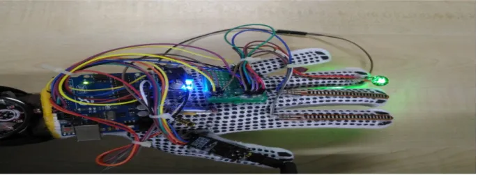
The Flex sensor-based glove is considered one of the most popular methods for gesture recognition. In this exploration, a motion detection architecture based on hand gestures is proposed for disabled patients of our country. In this model, users have to wear a wristband which includes a sensor called a Fleck sensor.
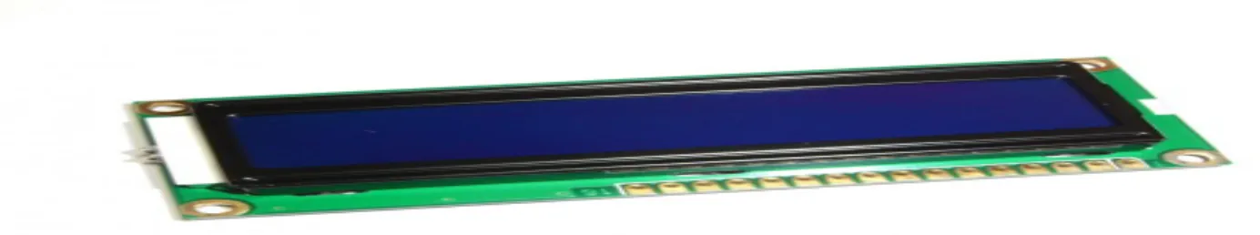
Based on the movement of that handle, the device will send a specific command to the receiver end, where an LCD Screen will show the information according to a user's needs.
INTRODUCTION
Objectives
Motivation
Project Features
BACKGROUND STUDY
Software/ Hardware Specifications
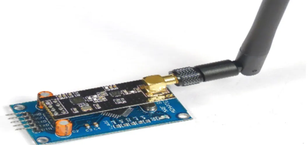
- NRF 24L01
- Features
- Pin Description
- Pin Functions
- Important Pin Functions
- Flex Sensor
- Features and Specifications
- Usage of Flex Sensor
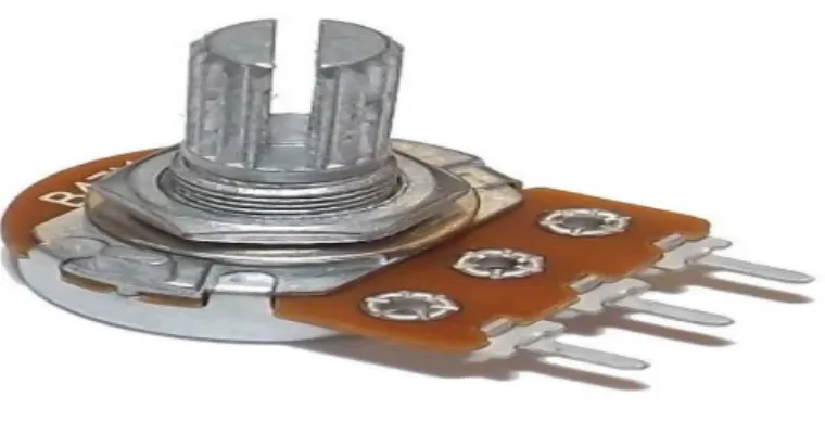
- Nature of Potentiometer
- Application of Potentiometer
- LCD Display
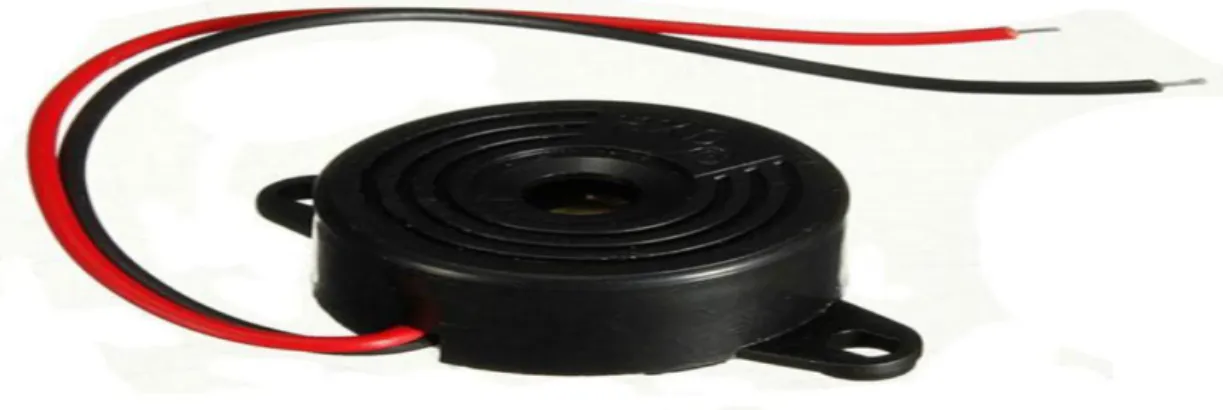
- ArduinoBuzzer
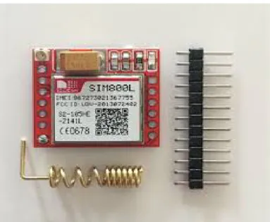
- GSM Module
- Features
- Buck Converter
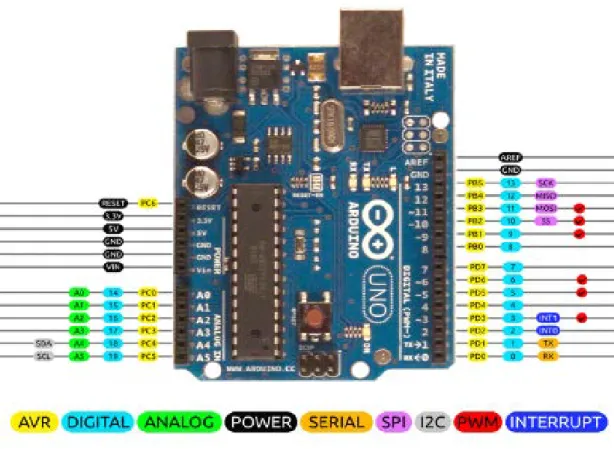
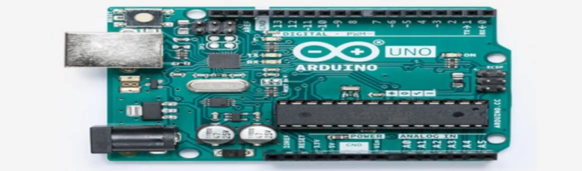
It has 14 advanced information/performance sticks, 6 of which can be used as PWM outputs, a 16 MHz earthenware resonator, an ICSP header, a USB connection, 6 simple data sources, a power jack and a reset latch. The Arduino Uno Board is different from all other boards and they will not use the FTDI USB-to-sequential driver contributed by them. The information voltage to the Arduino board when it uses an external power source instead of 5 volts from the USB union or another regulated power source).
Reset: Often used to add a reset hack to shields that prevent the one on the board. Proprietary innovation by Spectra Symbol - they guarantee that these sensors were used in the first Nintendo Power Glove. The opposition of the bend sensor changes when the metal pads are outside the curve. Connector is 0.1" spread and breadboard friendly.
The useful range of the sensor can be bent without problems, but care must be taken to limit bending outside the useful range. At the point where power is limited by resistance, often the vitality in power is transformed into another kind of vitality, such as light or heat. It has no source resistance on the basis that no current flows through the potentiometer when it is set.
With uninformed content, LCDs are acquired in fixed picture or discretionary picture, which appear or hide as the actual words, figures or 7-part presentation. This sensor gives a simple flag and the sensor can be driven with 3V or 5V, the current consumption of the sensor is 4mA, which is great for versatile applications. The sensor comes with three 24" long patch cords and a male berg header towards the end.
The GSM convention was chosen in light of the fact that it is not supported at the mobile phone stage. The buck converter is so named in light of the fact that the inductor reliably "bucks" or acts against the information voltage. The output voltage of a perfect buck converter is equivalent to the product of the buck duty cycle and the supply voltage.
The test board has pieces of metal lugs that run under the board, yellow square shapes, and connect a collection of five gaps on the board. The top and bottom lines of the apertures are connected on a flat plane, while the gaps in the middle areas are connected vertically.
DESING AND PLANNING
Flow Chart
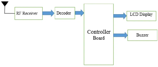
Block Diagram
- Transmitter Unit
After decoding the signals, the controller board sends signal to LCD, Buzzer, LCD light.
METHODOLOGY
- Introduction
- Burning the Boot loader
- Libraries for Arduino Coding
- Flex Sensor
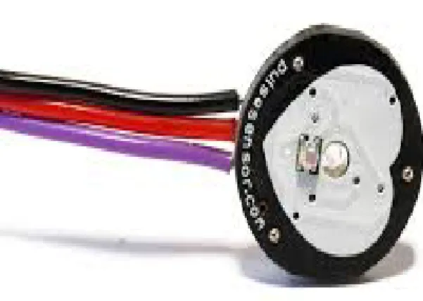
- Pulse Sensor
- Circuit Diagram
- Transmit Unit
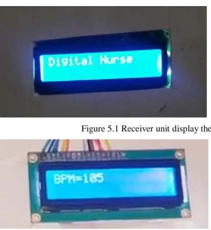
- Receiver Unit
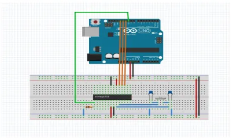
The ATmega328p has the Arduino boot loader on it, you can transfer projects to it using the USB-to-sequential converter (FTDI chip) on an Arduino board. To do that, you remove the microcontroller from the Arduino board so that the FTDI chip can talk to the microcontroller on the breadboard. The outline on the right tells the best way to connect the RX and TX lines from the Arduino board to the ATmega328 on the breadboard.
Here the GSM module is connected to the Arduino where pin D0 is connected to RXD and D1 to TXD. Another pin of the GSM module VCC is connected to the LM (Buck converter) used for power control. The Flex sensor 1 is connected to Arduino pin D3 and the Flex sensor 2 is connected to D9 pin.
NRF pin 2 connected to Arduino pin 3v, NRF pin 3 connected to Arduino pin D8, NRF pin 4 connected to Arduino pin D13, NRF pin 5 connected to Arduino pin D11, NRF pin 6 connected to Arduino pin D7, NRF pin 7 is connected z Arduino pinom D10. LCD screen pin VEE connected to Arduino A0, R5 connected to Arduino A1, R0 connected to Arduino A2, D4 connected to Arduino A3, D5 connected to Arduino A4, D6 connected to Arduino A5, D7 connected to Arduino GND pin. NRF pin 2 is connected to Arduino pin 3v, NRF pin 3 is connected to Arduino pin D8, NRF pin 4 is connected to Arduino pin D13, NRF pin 5 is connected to Arduino pin D11, NRF pin 6 is connected to Arduino pin D7, NRF pin 7 is connected z Arduino pinom D10.
IMPLEMENTATION
Introduction
Working Procedure
Results
When a patient will bend the middle finger, the transmission unit will generate a signal with the help of bend sensor and other devices and transmit it through the NRF module. The receiver unit will receive the signal and convert the signal into a message "Food/water please". When a patient will bend the index finger, the transmission unit will send an emergency message and make a phone call to the user's or nurse's cell phone.
FUTURE WORK AND CONCLUSION
Future work
Conclusion
1] Voice and EOG-based real-time personalized self-assistance technology for the disabled. Clinical Engineer Bioengineering Research Service Veterans Administration Prosthetics Center 252 Seventh Avenue New York, New York 10001 [3] Hand Gesture Recognition Application for the Physically Handicapped, Volume 3 Edition. 4] Gesture Control Intelligent Wireless Wheelchair for the Physically Handicapped, Proceedings, 15 September 2013, Pune, India.
Appendix - A