This thesis entitled “A Network Design and Simulation of a Smart Train Station Using Cisco Packet Tracer” is presented by Md. Ashikur Rahman, with ID has completed the report of the following thesis titled “A Network Design and Simulation of a Smart Train Station Using Cisco Packet Tracer.” I completed this project under the supervision of lecturer Ahmed Imran Kabir, Bachelor of Business and Administration (BBA), School of Business and Economics (SOBE), United International University (UIU). This research paper proposes a network design for an intelligent train station running centrally within a LAN.
Introduction
The smart station is designed from the perspective of Bangladesh, as this sector is one of the poorest transport sectors. Therefore this research is motivated to solve specific and significant segments of this transport sector to reduce the suffering of passengers and facilitate the daily operation of railway stations. Further, this project was initiated to solve the process of getting tickets into the black market trap.

Literature Review
Kabir et.al have developed a project on a network design of an airport using Cisco Packet Tracer[1]. Nathaniel et.al built a project under University of Agriculture, Markurdi, Nigeria of LAN using Cisco Packet Tracer[3]. Seth et.al conducted a study for implementing College Network scenario using Cisco Packet Tracer[13].
Research Methodology
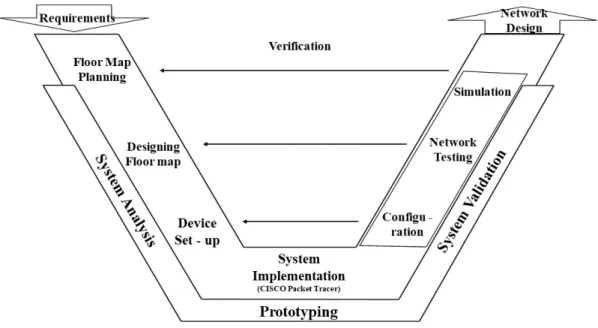
Due to the inefficiency of the railway management system, the challenge in this research is to design a proper floor plan for the railway station. The background represents an area suitable for the city, where all tasks and functions of the station, including easy accessibility for passengers, will ensure the most effective system of station management. Although people reach the station by road, the introduction of the metro will make it easier to get there on time.
Each space has its size measured according to the number and types of units required and a master measurement of the entire station spanning all departments, entrances, car parks and platforms. Once the station was designed, the file was modified under an interface design application called Figma. Using Figma, the station design is resized and edited several times to fit into Cisco Packet Tracer.
Once the drive PNG file is prepared, it is set to physical mode on Cisco Packet Tracer. The terminals, components and network devices were placed in the right places in all departments of the station design. These will result in a complete network simulation of the train station that can be centrally controlled and communicated.
Together with the combination of all these software, the network design of this railway station will be able to show its efficiency.
Introduction to Software
This software is primarily used for 2-dimensional and enhanced 3D modeling of any object, space and structure. It is required to draw significant infrastructural developments such as bridges, highways, apartments, airports, etc. It is widely used in construction by engineers, architects, project managers, graphic designers and many professionals.
Once removed, the data can be presented to customers on construction sites to obtain information on project costs, forecasting and material estimates. It is an interface design web application that is compatible with Windows as well as macOS. It focuses on the real-time combination of experiencing user interfaces on mobile and desktop and has lots of vector editing tools, prototyping and graphics.
This software is used for various computer platforms and is a simulation tool that allows users to design modern computer networks for network topologies. The packet tracer helps drag and drop devices and connections that are later configured with network devices to communicate where necessary. This software was essential for developing a network simulation in Cisco packet tracer to demonstrate a relevant and valuable project for a computer network design.
Finally, Cisco Packet Tracer will create a network design and simulation of all devices and configurations.
Planning and Designing
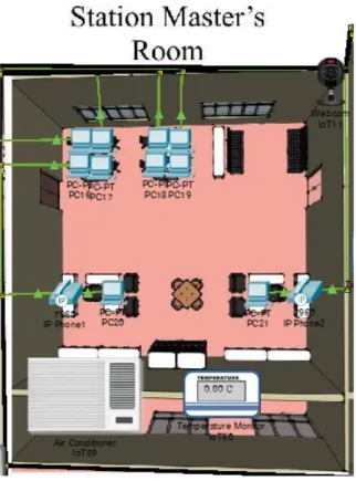
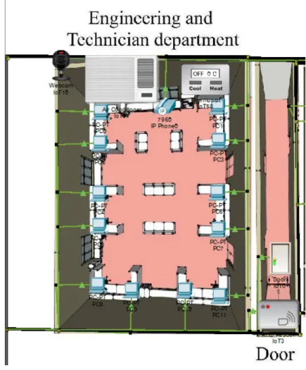
This department is responsible for the development and introduction of new devices and the implementation of any infrastructure that will run for easier and faster operations within the project. All train arrival and departure times are announced from this room. The signal core team gives the trains permission to pause and run on their track.
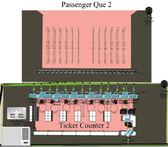
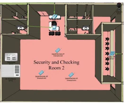
The information booth will answer all questions regarding train timetables and dates, fares and classes, and emergency information. The station is concerned about the safety of passengers, railway property and possible sabotage, so passengers will be carefully screened with sniffers and detectors to identify suspected illegal drugs and objects. This section consists of servers and network devices that act as end devices in all sections of the station.
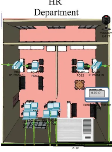
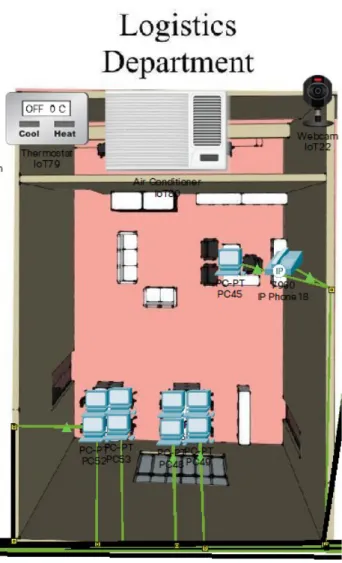
The HR department is responsible for recruiting and training the employees and personnel associated with the station in question. The departments control and guide the employees in each department and observe their daily tasks. Logistics is part of the station's service, which forms part of a systematic service flow to.
These sections are essential for a station to function flawlessly, and each unit is designed to accommodate a maximum number of IoT devices and configurations, making it an intelligent train station.
Implementation
Once the floor map planning and floor plan design is complete, the railway station image captured as a PNG file is placed in the Cisco Packet Tracer background. The study used the idea of customer experience in the physical interface of the package tracker. Connections and installation of the end device are performed in the logical interface of the software.
The end devices connected by wires use straight copper cables, coaxial cables and copper crossover cables, and the network devices are connected using serial DTE cables. In this project, nine switches engage all the end devices within the buttons next to the departments. In this study, static routing method was used, where all the routers were given their default gateway IP address.
The gateway's default IP address will be used for those end devices connected to its router via a switch. Each computer is assigned an IP address and a default gateway IP address for its specific router connections. IoT devices can be monitored and controlled remotely, so a server is required in addition to wireless routers.
Initially, the wireless router is set up with the default gateway IP address and SSID title. It can be concluded that all terminal devices have been placed according to the design of the department plan. The configuration of the network devices is the most crucial part of this packet tracer, as they centrally connect all end devices in the department.

Real Time Network Testing and Simulation in Cisco Packet Tracer
In the previous chapter, the end devices were attached to the switches and routers with cables and wireless routing support. Each machine is given its IP address and default gateway to connect with other end devices. End devices such as desktops, laptops and servers have features to send packets to any end device.
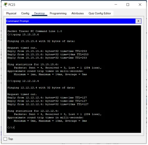
The user should open the command line icon and ping the IP address of any of the end devices. The command line will show the status of the four packets sent to the pinged IP address. If all packets appear lost, there is a configuration error on the end devices from both ends of the network devices.
If at least 3 received packets are shown, the end device with the IP address pinged by the sender is properly bound. Cisco Packet Tracer has real-time simulation features to trace packets that are transmitted over wires from sender to receiver through network devices and cables. Network testing showed that packets pinged by the sender via the IP address to the receiver were successful, indicating only one packet loss.
The simulation shows that packets travel without obstacles from the sender to the receiver through the cables and network devices.
Conclusion and Future Scope
The network design of the station is secured against its requirements at several levels. To improve the services of the railway station, the project is built with a combination of traditional and IoT devices. The project created is a LAN (Local Area Network) that uses the concept of DHCP, DNS and Static in Cisco Packet Tracer.
The overall design of the drive is explained on the physical interface, where the connections and processes are shown on the logical one. The report contains all the details and planning of the software, its demonstration and reliability for students interested in learning computer networking. The important fact of this thesis is that it was developed for the first basic principles of the prototype.
Rakhymbek, »DIZAJN IN SIMULACIJA VIRTUALNEGA LOKALNEGA OMREŽJA Z UPORABO CISCO PACKET TRACER,« Številka, vol. Lubis, »Designing Secured Cafe Network with Security Awareness Domain and Resource (SADAR) by Simulation using Cisco Packet Tracer,« v ACM International Conference Proceeding Series, Association for Computing Machinery, jul. Islam, »Smart University Network Module Implementation by Using Cisco CCNA s Packet Tracer,” Journal of Network Communications and Emerging Technologies, doi: 10.13140/RG.
Selby, “Network and Complex Systems Design and IoT Simulation for the Accra Smart City Effective Use of Scarce and Expensive Internet Bandwidth in Higher Education Institutions in Developing Countries View Project Network and Complex Systems and IoT Simulation for the Accra Smart City,” 2018 , [on the Web].