DESIGN AND SIMULATION OF AN ENTERPRISE NETWORK USING PACKET TRACER: A Case Study of a Model Secondary School
By
Yahya Faydah U10EE1019
A Final Year Project Submitted to the Department of Electrical and Computer Engineering ABU, Zaria in Partial Fulfillment of the Requirements for the Award of Bachelor of Engineering
(B.Eng.) Degree in Electrical Engineering.
i
DECLARATION
I, YAHYA FAYDAH hereby declare that all topics provided and discussed in this project report are a
result of my research and experience. It has never been presented nor published anywhere for the
award of any certificate. All sources of information have been specifically acknowledged by means of
references.
………. ………
YAHYA FAYDAH DATE
ii
CERTIFICATION
This is to certify that this project titled “DESIGN AND SIMULATION OF AN ENTERPRISE NETWORK USING PACKET TRACER: A Case Study of a Model Secondary School” was found to satisfy the requirement for the award of Bachelor of Engineering (B.Eng.) degree in the
Department of Electrical and Computer Engineering.
……….. ……….. Supervisor Date
Prof. M. B. Mu’azu
……….. ……….. Project Coordinator Date
Engr. M. J. Musa
……….. ……….. Head of Department Date
iii
DEDICATION
This project report is dedicated to the memory of my parents, Late Mallam Yahya M Babayo, a father
who passed on a love of reading and respect for education and Prof.A.I Mamman who taught me that
even the largest task can be accomplished if it is done one step at a time, And to all requirements
iv
ACKNOWLEDGEMENT
I wish to express my profound gratitude to God Almighty, the most Gracious and the ever merciful
and my parents, for their unrestrained support in every situation throughout my whole life.
I also wish to thank the Head of Department, Prof MB. Muazu, who is also my project supervisor for
his extensive coaching and guidance, and the students and staff of the department of Electrical and
Computer Engineering. This also includes Malam Yusuf and Malam Bashir of ICT Data Center,
Malam Kabir and Malam Bukhari of Mamman Kontagora Lab, and Malam Tukur as they were the
supportive backbones of this project. I will always be grateful to God for making me know Denis
Onyemachi and an exceptional classmate Stephen Edegbo, for their kind support all through. I really
appreciate all the services. May the most Divine reward you.
My appreciation goes to my dear husband, Salis Bara’u Salis, my grandparents, uncles and aunties, the
entire members of my family, friends and classmates for always being supportive and encouraging in
all my endeavors. This includes those that in one way or the other had stretched out helping arms or
seen me through. I am sincerely grateful to you all.
v ABSTRACT
An E-learning system comprising of voice and data distribution service has been designed in this
project using a secondary school model as a case study. It involved identification, determination and
specification of data communication products and services that best satisfy user need in a way that
gives room for network scalability, redundancy and effective manageability. The project also focuses
on the design of an enterprise network by effectively deploying technologies and protocols as Voice
over IP, Access Control Lists, EIGRP routing, Fiber Optics, VLSM for addressing, Inter VLAN
routing, Network Address Translation, use of DHCP and wireless routing. This project should be
useful to Network Communications Engineers as it covers the major requirement that necessitates an
vi
2.3.1 Requirements of an Enterprise Network ... 7
2.4 Network Protocol ... 8
2.5 Network Devices ... 8
2.5.1 Routers ... 8
2.5.2 Switches ... 10
2.5.2.1 Virtual LANS in Switches ... 10
2.6 Wireless Access Point (WAP) ... 10
2.7 Voice over Internet Protocol (VoIP) ... 12
2.8 Access Control Lists ... 12
2.8.1 Why Use ACL ... 13
2.8.2 Types of Access Control Lists ... 13
2.8.2.1 Standard Access-List ... 13
vii
3.1.5 Dynamic Host Configuration Protocol (DHCP) ... 25
3.1.6 Wireless Connectivity ... 25
3.1.7 VoIP Configuration ... 26
3.1.8 Access Control List Configuration ... 27
3.1.9 Configuring Network Address Translation ... 27
CHAPTER FOUR ... 28
RESULTS AND DISCUSSIONS ... 28
4.1 Show IP Route Command on Core Router ... 28
4.2 Verifying Interface Configurations ... 28
4.3 Automatic Assignment of IPs Using DHCP ... 29
viii
5.2 Conclusion ... 33
5.3 Limitations ... 33
5.4 Recommendations for Future Work ... 34
APPENDIX A ... 36
APPENDIX B ... 39
ix
TABLE OF FIGURES
Figure 2.1 The Hierarchical Architecture of a Network ... 6
Figure 2.2 The Interface of a Switch with Ports ... 10
Figure 2.3 Wireless Connection of Networks ... 11
Figure 2.4 How a VoIP Works In Networks ... 12
Figure 2.5 A Packet Tracer Interface ... 16
Figure 2.6 The OSI and TCP/IP Layers ... 18
Figure 2.7 A Peer-to-Peer Network ... 19
Figure 2.8 a Client-Server Network ... 20
Figure 3.1 The Architectural View of the Network Design ... 22
Figure 3.2 Part of the Fiber Optic Connectivity of the Network ... 23
Figure 3.3 The GUI Interface of a Linksys WiFi ... 25
Figure 4.1 The IP Route of the Core Router ... 28
Figure 4.2 Configured Interface of Core Router ... 28
Figure 4.3 The Automatically Assigned IP Addresses Of PC0 ... 29
Figure 4.4 Ping Statistics from PC2 to ISP Server ... 30
Figure 4.5 Connection to the Linksys Router ... 31
x
LIST OF ABBREVIATIONS NAT - NETWORK ADDRESS TRANSLATOR
DHCP - DYNAMIC HOST CONFIGURATION PROTOCOL
DNS - DOMAIN NAME SERVER
VoIP - VOICE OVER INTERNET PROTOCOL
EIGRP - ENHANCED INTERIOR GATEWAY ROUTING PROTOCOL
RIP - ROUTING INFORMATION PROTOCOL
OSPF - OPEN SHORTEST PATH FIRST
BGP - BORDER GATEWAY PROTOCOL
OSI - OPEN SYSTEMS INTERCONNECTIONS
ISO - INTERNATIONAL STANDARDS OF ORGANISATION
CPU - CENTRAL PROCESSING UNIT
Wi-Fi - WIRELESS FIDELITY
CIDR - CLASSLESS INTER DOMAIN ROUTING
VLSM – VARIABLE LENGTH SUBNET MASKING
ACL - ACCESS CONTROL LISTS
NIC – NETWORK INTERFACE CARD
VLAN – VIRTUAL LOCAL AREA NETWORK
LAN – LOCAL AREA NETWORK
xi CLI – COMMAND LINE INTERFACE
TTL – TIME TO LEAVE
HTML – HYPER TEXT MARKUP LANGUAGE
1
CHAPTER ONE INTRODUCTION 1.1 Background
Information and communication are two of the most important strategic issues for the success of every
enterprise. While today nearly every organization uses a substantial number of computers and
communication tools (telephones, fax, and personal handheld devices), they are often still isolated.
While managers today are able to use the newest applications, many departments still do not
communicate and much needed information cannot be readily accessed.
Networking is all about imagination and it’s difficult to track movement of packets in a real-time
environment, thus various networking concepts can be explained by creating a virtual environment,
showing the moment of packets, exactly as it would happen in real-time. Networks must meet the
current needs of organizations and be able to support emerging technologies as new technologies are
adopted. Network design principles and models can help a network engineer design and build a
network that is flexible, resilient, and manageable. This project introduces network design concepts,
principles, models, and architectures. It covers the benefits that are obtained by using a systematic
design approach. Emerging technology trends that will affect network evolution are also discussed.
(Hierarchical Network Design-Layer of The Hierarchical Network Design Model.)
1.2 Aim and Objectives
This project aims at the design and simulation of an enterprise network using Packet Tracer. The
design is based on the hierarchical architecture with a model secondary school as a case study.
The objectives of the study are as follows:
a) Design and simulation of an enterprise network, with a model Secondary school as a case study,
using Packet Tracer
2 1.3 Problem Statement
When network devices communicate with many other devices, the workload required of the CPUs on
the devices can be burdensome. For example, in a large flat (switched) network, broadcast packets are
burdensome. As such the modular nature of the hierarchical design model is to enable accurate
capacity planning within each layer of the hierarchy, thus reducing wasted bandwidth. Network
management responsibility and network management systems should be distributed to the different
layers of a modular network architecture to control management costs.
1.4 Methodology
In order to design and implement a Hierarchical Model of an Enterprise Network the following
methodology was used:
a) Conceptualizing the Ideas.
b) Designing the Network Architecture
c) Use Of Fiber Optic Connectivity
d) Configuration of Devices in accordance to Topology
e) Use of Dynamic Host Configuration Protocol
f) Network Troubleshooting
1.5 Project Outline
Chapter one gives a brief introduction, background, scope and methodologies used. Chapter Two mostly
dealt with the literature review where the fundamental concepts were carried out. More emphasis was
made in the methods used in designing and implementing the project’s Chapter Three. Extensive
simulation and network troubleshooting including their various results are presented in Chapter Four and
3
CHAPTER TWO LITERATURE REVIEW 2.1 Network Design
Regardless of network size or requirements, a critical factor for successful implementation of any
network design is to follow the good structured engineering principles as listed below:
Hierarchy
In looking at how structured design rules should be applied to the campus, it is useful to look at the
problem from two perspectives. First, what is the overall hierarchical structure of the campus and
what features and functions should be implemented at each layer of the hierarchy? Second, what are
the key modules or building blocks and how do they relate to each other and work in the overall
hierarchy? Starting with the basics, the campus is traditionally defined as a three-tier hierarchical
model comprising the core, distribution, and access layers. The key principle of the hierarchical
design is that each element in the hierarchy has a specific set of functions and services that it offers
and a specific role to play in each of the design.
Modularity
The modules of the system are the building blocks that are assembled into the larger campus. The
advantage of the modular approach is largely due to the isolation that it can provide. Failures that
occur within a module can be isolated from the remainder of the network, providing for both simpler
problem detection and higher overall system availability. Network changes, upgrades, or the
introduction of new services can be made in a controlled and staged fashion, allowing greater
flexibility in the maintenance and operation of the campus network. When a specific module no
longer has sufficient capacity or is missing a new function or service, it can be updated or replaced
4 Flexibility
The ability to modify portions of the network, add new services, or increase capacity without going
through a major fork-lift upgrade are key considerations to the effectiveness campus designs. The
structured hierarchical design inherently provides for a high degree of flexibility because it allows
staged or gradual changes to each module in the network fairly independently of the others.
Resilience
While the principles of structured design and the use of modularity and hierarchy are integral to the
design of campus networks they are not sufficient to create a sustainable and scalable network
infrastructure. It is not enough that a campus network be seen as being complete solely because it
correctly passes data from one point to another. As shown by the numerous security vulnerabilities
exposed in software operating systems and programs in recent years, software designers are learning
that to be correct is no longer enough. Systems must also be designed to resist failure under unusual
or abnormal conditions. One of the simplest ways to break any system is to push the boundary
conditions—to find the edges of the system design and look for vulnerabilities. To break a network,
it’s a similar approach. Introduce a volume of traffic, number of traffic flows or other anomalous
condition to find the vulnerabilities (Enterprise Campus 3.0 Architecture:Overview and Framework)
2.2 Multi-Tiered Architecture
The use of Multi-tiered Architecture, Enterprise networking, network security, ACL’s, Network
Protocols, IP addressing, VoIP are all important aspects that make up this project. They are
explained as follows:
Network design experts have developed the hierarchical network design model to help you develop
5
choose the right systems and features for the layer. For example, high speed WAN routers can carry
traffic across the enterprise WAN backbone, medium speed routers can connect buildings at each
campus, and switches can connect user devices and servers within buildings. (Hierarchical Network
Design-Layer of The Hierarchical Network Design Model.)
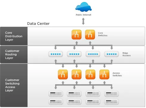
A typical hierarchical topology as in Figure 2.1 consists of the following:
A Core layer of high end routers and switches that are optimized for availability and
performance.
A Distribution layer of routers and switches that implement policies.
An Access layer that connects users via lower end switches and wireless access points.
Each layer of the hierarchical model has a specific role. The core layer provides optimal transport
between sites. The distribution layer connects network services to the access layer, and implements
policies regarding security, traffic loading, and routing. In a WAN design, the access layer consists
of the routers at the edge of the campus networks. In a campus network, the access layer provides
6
Figure 2.1 The Hierarchical Architecture of a Network
2.3 Enterprise Networks
An enterprise network can be thought of as a “plug-and-play” platform for connecting many
different computing devices. In this platform scenario, no user or group is an island. All systems can
potentially communicate with all other systems while maintaining reasonable performance, security,
and reliability.
This has largely been achieved with Internet protocols and Web technologies that provide better
results at lower cost and fewer configuration problems than the enterprise computing models.
TCP/IP is a unifying internetwork protocol that lets organizations tie together workgroup and
division LANs, and connect with the Internet. Web protocols (HTTP, HTML, and XML) unify user
7
browser is like a universal client, and Web servers can provide data to any of those clients. Web
servers are distributed throughout the enterprise, following distributed computing models. Multitier
architectures are used, in which a Web client accesses a Web server and a Web server accesses
back-end data sources, such as mainframes and server farms. An enterprise network would connect
all the isolated departmental or workgroup networks into an intercompany network, with the
potential for allowing all computer users in a company to access any data or computing resource. It
would provide interoperability among autonomous and heterogeneous systems and have the
eventual goal of reducing the number of communication protocols in use (Enterprise Campus 3.0
Architecture:Overview and Framework).
2.3.1 Requirements of an Enterprise Network
The following gives an insight into how good an enterprise network should be
a) Scalability – How well will the system(s) scale under volume and load. This includes what is
known as horizontal and vertical scaling. Horizontal means that the system will scale simple by
adding more resource units (e.g., more servers). Vertical scaling is the increase of one or more
resources (e.g., memory, CPUs)
b) Reliability – What is the elasticity or fault tolerance under multiple conditions and stimuli
c) Extensibility – Can the system’s core functionality do more without rewrite
d) Flexibility – How well does the system respond to integration or implementation in different
environments
e) Availability - How dependable is the system uptime
f) Maintainability – How easy is it to maintain the code and components of the system
8 2.4 Network Protocol
Network protocols are standards that allow computers to communicate. A protocol defines how
computers identify one another on a network, the form that the data should take in transit, and how
this information is processed once it reaches its final destination. Protocols also define procedures for
handling lost or damaged transmissions or "packets" [6]. TCP/IP (for UNIX, Windows NT,
Windows 95 and other platforms), IPX (for Novell NetWare), DEC net (for networking Digital
Equipment Corp. computers), AppleTalk (for Macintosh computers), and NetBIOS/NetBEUI (for
LAN Manager and Windows NT networks) are the main types of network protocols in use today.
Although each network protocol is different, they all share the same physical cabling. This common
method of accessing the physical network allows multiple protocols to peacefully coexist over the
network media, and allows the builder of a network to use common hardware for a variety of
protocols. (Computer Network Demystified :The TCP/IP Reference Model )
2.5 Network Devices
Typical network devices are described in this section.
2.5.1 Routers
A router is a physical network device (usually running proprietary software) that is used to connect
several network segments into one network or an existing large network into smaller subnets.
Internet destination using routing protocols to exchange information and determine routing decisions.
Routing exists in an intranet between routing devices and on the ISP network between a border
9
Routers maintain routing tables that are consulted every time a packet needs to be redirected from
one interface or segment to another. Routes can be added manually to the routing table—a very
secure but less-manageable method, depending on the size of the network—or be updated
automatically using routing protocols such as the following:
a) Routing Information Protocol (RIP)/RIPv2
b) Interior Gateway Routing Protocol (IGRP)
c) Enhanced Interior Gateway Routing Protocol (EIGRP)
d) Open Shortest Path First (OSPF), Border Gateway Protocol (BGP)
e) Exterior Gateway Protocol (EGP)
f) Intermediate System-Intermediate System (IS-IS)
Routing protocols employ different techniques to prevent routing loops (when a packet is rerouted
indefinitely without finding the destination). Some of these techniques are
a) Counting to infinity
b) Route poisoning
c) Split horizon
Knowing how the routing protocols work is extremely important in avoiding trouble situations, such
as:
a) A hacker sending a route update to your network and poisoning (marking as downed) an
important route to cause a DoS condition
b) The creation of a routing loop that overloads the router and causes the network to become very
slow and appear over- utilized\The update of a route to send all outbound traffic to a different
host, which would then forward it to the ISP, launching an active interception or
10 2.5.2 Switches
Switches, as in Figure 2.2, are a special type of hub that offers an additional layer of intelligence to
basic, physical-layer repeater hubs. A switch must be able to read the MAC address of each frame it
receives. This information allows switches to repeat incoming data frames only to the computer or
computers to which a frame is addressed. This speeds up the network and reduces congestion.
Switches operate at both the physical layer and the data link layer of the OSI Model.
Figure 2.2 The Interface of a Switch with Ports
2.5.2.1 Virtual LANS in Switches
A VLAN is a logical grouping of network users and resources connected to administratively defined
ports on a switch. When VLANs are created, it becomes possible to create smaller broadcast domains
within a layer 2 switched internetwork by assigning different ports on the switch to service different
subnetworks. A VLAN is treated like its own subnet or broadcast domain, meaning that frames
broadcast onto the network are only switched between the ports logically grouped within the same
VLAN.
2.6 Wireless Access Point (WAP)
A wireless network adapter card with a transceiver sometimes called an access point, broadcasts and
receives signals to and from the surrounding computers and passes back and forth between the
wireless computers and the cabled network as in Figure 2.3. Access points act as wireless hubs to
11
port to allow the wireless network to be bridged to a traditional wired Ethernet network (Network
Devices)
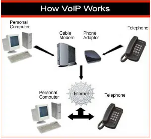
12 2.7 Voice over Internet Protocol (VoIP)
Voice over Internet Protocol is a category of hardware and software that enables people to use the
Internet as the transmission medium for telephone calls by sending voice data in packets using IP
rather than by traditional circuit transmissions of the PSTN.
One advantage of VoIP is that the telephone calls over the Internet do not incur a surcharge beyond
what the user is paying for Internet access, much in the same way that the user does not pay for
sending individual emails over the Internet. (Keagy, Integrating Voice and Data Networks, 2000).
Figure 2.4 shows how VoIP works in a network.
Figure 2.4 How a VoIP Works In Networks
2.8 Access Control Lists
Access Control List (ACL) are filters that enables one to control which routing updates or packets
are permitted or denied in or out of a network. They are specifically used by network administrators
13
control traffic into and out of your network; this control can be as simple as permitting or denying
network hosts or addresses. ACLs can be configured for all routed network protocols.
The most important reason to configure ACLs is to provide network security. However, ACLs can
also be configured to control network traffic based on the TCP port being used (Easa).
2.8.1 Why Use ACL
The following are some of the reasons for configuring ACL in a network:
a) Limits network traffic to increase network performance.
b) ACLs provide traffic flow control by restricting the delivery of routing updates.
c) It can be used as additional security.
d) Controls which type of traffic are forwarded or blocked by the router.
e) Ability to control which areas a client access.
2.8.2 Types of Access Control Lists
The types of ACLs used in networks are described in the following sub-sections:
2.8.2.1 Standard Access-List
Standard access lists create filters based on source addresses and are used for server based filtering.
Address based access lists distinguish routes on a network you want to control by using network
address number (IP). Address-based access lists consist of a list of addresses or address ranges and a
statement as to whether access to or from that address is permitted or denied.
2.8.2.2 Extended Access Lists
Extended access lists create filters based on source addresses, destination addresses, protocol, port
number and other features and are used for packet based filtering for packets that traverse the
14
network and one identifying the node. The Class of the address and the subnet mask determine which
part belongs to the network address and which part belongs to the node address (Easa).
There are 5 different address classes. One can determine which class any IP address is in by
examining the first 4 bits of the IP address as follows:
Class A addresses begin with 0xxx, or 1 to 126 decimal.
Class B addresses begin with 10xx, or 128 to 191 decimal.
Class C addresses begin with 110x, or 192 to 223 decimal.
Class D addresses begin with 1110, or 224 to 239 decimal.
Class E addresses begin with 1111, or 240 to 254 decimal.
2.9.1 Subnet Masking
Applying a subnet mask to an IP address allows you to identify the network and node parts of the
address. The network bits are represented by the 1s in the mask, and the node bits are represented by
the 0s. Performing a bitwise logical AND operation between the IP address and the subnet mask
results in the Network Address or Number.
2.9.2 Default subnet masks
The following are the default subnet masks:
Class A - 255.0.0.0 - 11111111.00000000.00000000.00000000
Class B - 255.255.0.0 - 11111111.11111111.00000000.00000000
15
address blocks, which contain over 16 Million host addresses! Only a tiny percentage of the allocated
Class A and Class B address space has ever been actually assigned to a host computer on the
Internet.
The use of a CIDR notated address is the same as for a Classful address. Classful addresses can
easily be written in CIDR notation (Class A = /8, Class B = /16, and Class C = /24)
2.9.3 Network Address Translation
In Network Address Translation, Addresses can be assigned dynamically. Dynamic NAT allows
hosts on a private network that have IP addresses to access a public network such as the internet.
Dynamic NAT occurs when a router assigns an outside global address from a predefined address, or
pool of address to an inside private network device. The NAT advantage is that individual hosts are
not directly accessibly from the public internet.
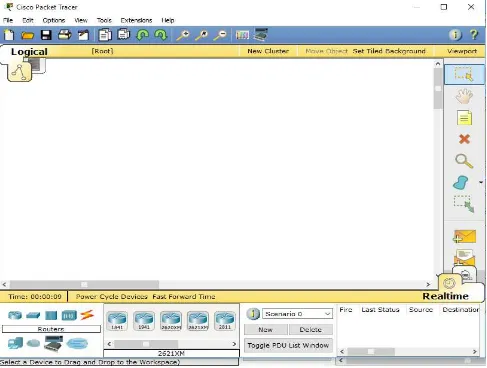
2.10 Cisco Packet Tracer
Cisco Packet Tracer is a powerful network simulation program that allows the experimentation with
network behavior and ask “what if” questions. Packet Tracer provides simulation, visualization and
authoring, assessment, and collaboration capabilities and facilitates the teaching and learning of
complex technology concepts. Packet Tracer supplements physical equipment in the classroom by
allowing students to create a network with an almost unlimited number of devices, encouraging
practice, discovery, and troubleshooting. With Packet Tracer, one can build, configure, and
16
with other students. Most importantly, Packet Tracer helps in creating own virtual “network worlds”
for exploration, experimentation, and explanation of networking concepts and technologies. A
typical interface is as shown in Figure 2.5
17 2.11 Network Models
These are models that define a set of network layers and how they interact. There are several
different network models depending on what organization or company started them. The most
important two are described in the following subsections.
2.11.1 The TCP/IP Model
This model is sometimes called the DOD model since it was designed for the department of
defense. It is also called the internet model because TCP/IP is the protocol used on the
internet. It is the basic communication language or protocol of the Internet. It can also be used
as a communications protocol in a private network (either an intranet or an extranet). When
direct access to the Internet is set up, the computer is provided with a copy of the TCP/IP
program just as every other computer that may send messages to or get information from also
has a copy of TCP/IP.
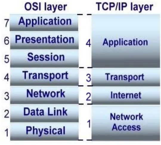
2.11.2 OSI Network Model
The International Standards Organization (ISO) has defined a standard called the Open Systems
Interconnection (OSI) reference model as in Figure 2.6. It is a conceptual model that characterizes
and standardizes the internal functions of a communication system by partitioning it into
abstraction layers. The model is a product of the Open Systems Interconnection project at the
International Organization for Standardization. The purpose of the OSI reference model is to
18
create will interoperate, and to facilitate clear comparisons among communications tools.
Figure 2.6 The OSI and TCP/IP Layers
2.12 Internet
The Internet is a global system of interconnected computer networks that use the standard Internet
protocol suite (TCP/IP) to link several billion devices worldwide. It is an international network of
networks that consists of millions of private, public, academic, business, and government packet
switched networks, linked by a broad array of electronic, wireless, and optical networking
technologies. The Internet carries an extensive range of information resources and services, such as
the inter-linked hypertext documents and applications of the World Wide Web (WWW), the
infrastructure to support email, and peer-to-peer networks for file sharing and telephony.
2.13 Intranet
An intranet is a computer network that uses Internet Protocol technology to share information,
operational systems, or computing services within an organization. This term is used in contrast to
19
Sometimes, the term refers only to the organization's internal website, but may be a more extensive
part of the organization's information technology infrastructure, and may be composed of multiple
local area networks. The objective is to organize each individual's desktop with minimal cost, time
and effort to be more productive, cost efficient, timely, and competitive.
An intranet may host multiple private websites and constitute an important component and focal
point of internal communication and collaboration. Any of the well-known Internet protocols may be
found in an intranet, such as HTTP (web services), SMTP (e-mail), and FTP (file transfer protocol).
Internet technologies are often deployed to provide modern interfaces to legacy information systems
hosting corporate data.
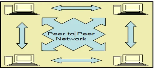
2.14 Peer-To-Peer Networks
Peer-to-peer networks, as in Figure 2.7, are more commonly implemented where less than ten
computers are involved and where strict security is not necessary. All computers have the same
status, hence the term 'peer', and they communicate with each other on an equal footing. Files, such
as word processing or spreadsheet documents, can be shared across the network and all the
computers on the network can share devices, such as printers or scanners, which are connected to any
one computer.
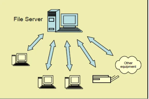
20 2.15 Client/server networks
Client/server networks, as in Figure 2.8, are more suitable for larger networks. A central computer,
or 'server', acts as the storage location for files and applications shared on the network. Usually the
server is a higher than average performance computer. The server also controls the network access of
the other computers which are referred to as the 'client' computers. Typically, teachers and students
in a school will use the client computers for their work and only the network administrator (usually a
designated staff member) will have access rights to the server. (Djieva)
21
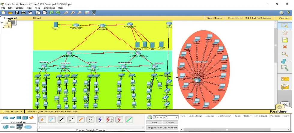
CHAPTER THREE DESIGN METHODOLOGY 3.1 Network Design
The network was designed using different technologies which were very important and crucial for
the completion of the task at hand. These technologies deployed were
a) The Network Architecture
The core router had one of its interface connected to the ISP and the other to the De-Militarized Zone
(DMZ). The DMZ had a switch which hosted a server firm representing an FTP, Web, E-mail and
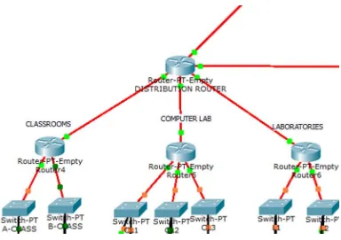
Fire wall servers as in Figure 3.1. The distribution layer had two main routers and six aggregate
routers representing the following units of the school: Classrooms, Laboratories, Computer
Laboratory, Conference Room, Staff Room, Admin Unit and the Principal’s office. The listed units
22
the administrative switches.To each switch was a server attached this was due to the fact that there
were different network addresses and VLAN’s,therefore the servers helped assign automatic IP
addresses to all pc’s in the access layer.Added to that,IP phones were connected to the
Administrative block and conference room switches.Partaining IP addressing,the entire network had
private IP adressing configured to it.In the sense that ISP router had a network address of
192.168.0.0,The core,distribution and access layer had a network address of 10.0.0.0.While the
internet interface of the wireless adapter had a network address of 10.0.0.0,it router’s network
address was 192.168.0.0.
23 3.1.2 Network Connection
As the packet tracer layer three switches (the multi-layer switch) could not provide fiber optic
connectivity, generic devices were used. This was because fiber optic connection, as in Figure 3.2,
covered longer distances. At the core and distribution layer, generic routers were used as they had
interfaces for both Serial and fiber optic connectivity. Generic switches were also used at the access
layer.
Figure 3.2 Part of the Fiber Optic Connectivity of the Network
3.1.3 Network Protocol
The EIGRP (Enhanced Interior Gateway Routing Protocol) was used as it is a hybrid routing
protocol specifically meant for routing numerous routers across an enterprise network. A total
number of ten routers were configured with the routing protocols. As such with the network
24
For example the core router was configured in global configuration mode as follows:
COREROUTER(config)#router eigrp 1
COREROUTER(router)#network 10.0.0.0
With the network address assigned, neighboring routers with IP addresses that fall under the same
network will recognize each other.
3.1.4 VLAN Configuration
Due to segmentation of blocks and devices, each switch acted as a VLAN of its own. The VLAN’s
were first configured from the VLAN data base by assigning a number and a name to each VLAN.
For example the VLANs assigned to the classroom switches were named A-CLASS and B-CLASS
with numbers 100 and 200 respectively.
When assigning IP addresses, all the ports on a switch were assigned to the VLAN meant for it
thereafter configuring it in global configuration mode as thus:
A-CLASS (config) #interface VLAN 100
A-CLASS (config-if) #IP add 10.0.91.2 255.255.255.0
A-CLASS (config-if) #IP default-gateway 10.0.91.1
25 3.1.5 Dynamic Host Configuration Protocol (DHCP)
Devices in the access layer were many and there appeared a possibility that it might expand,
therefore DHCP used to automatically assign IP addresses via routers acting as gateways to each
switch as seen below:
3.1.6 Wireless Connectivity
Wireless access points were configured to automatically assign IP addresses to computers nearby.
This was done to ease excess connection of devices. Added to the fact that there will be need for
flexibility any time a device has to be added to the network. For this purpose, a Linksys Wi-Fi was
configured as in Figure 3.3. For it to be connected to the network, its interfaces had to be connected
to a switch port. Devices nearby require a Linksys WPC-300N module to be connected.
26 3.1.7 VoIP Configuration
To enable voice communication via IP phones, routers and switches were configured. The only
router that could enable telephony service was the 2811 router. Hence the connection had to be done
by fast Ethernet cabling. From IP phones to 2811 router. Thereafter connecting the 2811 router to the
DMZ router using a serial DCE cable with the help of an NM8A/S module on the router.
Configurations were done sequentially as seen below (a DHCP pool to accommodate the IP phones
27 3.1.8 Access Control List Configuration
To secure and control the network from accessing certain networks, the access control list was
configured and assigned for example students were denied accessing the private web server as such
the Fa 3/0 interface was configured while those in the admin block were permitted.
CORE ROUTER>enable
CORE ROUTER#configure terminal
CORE ROUTER(config)#access-list 10 deny 10.0.20.0 0.0.0.255
CORE ROUTER(config)#access-list 10 permit host 10.0.92.1 0.0.0.255
CORE ROUTER(config)#access-list 10 deny 10.0.30.0 0.0.0.255
CORE ROUTER(config)#access-list 10 permit any
CORE ROUTER(config)#interface Fa 3/0
CORE ROUTER(config-if)#ip access-group 1 in
CORE ROUTER(config-if)#exit
CORE ROUTER(config)#interface Fa 0/0
CORE ROUTER(config-if)#ip access-group 1 in
CORE ROUTER(config-if)#exit
3.1.9 Configuring Network Address Translation
NAT configurations were placed into one of two: inside and outside. Inside indicates traffic coming
from within the school’s network and the outside network com an external network, in this case, the
ISP.A static NAT translation was configured between the dedicated public address and the dedicated
28
CHAPTER FOUR
RESULTS AND DISCUSSIONS
The results and analysis of tests carried out are discussed in the following sections
4.1 Show IP Route Command on Core Router The result of the “show ip” is as shown in Figure 4.1
Figure 4.1 The IP Route of the Core Router
4.2 Verifying Interface Configurations
The result of this command is as shown in Figure 4.2
29 4.3 Automatic Assignment of IPs Using DHCP
The result of the IP configuration is as shown in Figure 4.3
30 4.3 PING Command
The ping command, as in Figure 4.4, is the basic command used to check for connectivity between
devices. It can be done on either switches, routers, servers or computers. In routers and switches the
command is applied in the privilege mode while on severs and routers it takes place in the command
prompt interface. The main requirement of a network is for data to travel at the shortest available
time. As seen below packets were sent to the DNS server at a period of 2ms.
31 4.4 Wireless Network
After all the necessary configurations, the wireless laptops used automatically connected to the
Linksys Router as seen in Figure 4.5.
32 4.5 Access to Website
The website server, as in Figure 4.6, was configured in the DMZ and devices in the entire network
could link up to it with the IP address.
33
CHAPTER FIVE
CONCLUSION AND RECOMMENDATIONS 5.1 Significance
After the implementation and testing of network; Troubleshooting became easy as there were no
complex routing interaction. It was seen to it that devices could reach out to any point of the network
i.e. connectivity within all devices was ensured.Moreso the network could double or triple in size
without major design changes i.e. it can be flexible at any instant.
5.2 Conclusion
With the recent advancements in technology, more reliable and convenient means of designing
networks will be required The aim of this project being an enterprise network, is to ensure that no
device remains onto itself, there should be speed in the connectivity, addition of devices should not
hinder the transfer of packets, added to that interfaces not meant to accesses should be blocked. It can
be concluded that this aims were accomplished and totally completed to working and troubleshooting
standards.
5.3 Limitations
When evaluating management solutions for enterprise networks, design simulators should keep in
mind the following:
a) There will be need to create fiber optic modules in the 3560 layer 3 switch.
b) Generic routers should have modules that enable telephony service, rather than being specific to
2811 routers alone.
c) Servers should have interfaces that will enable VoIP configuration.
34 5.4 Recommendations for Future Work
a) Additional access control lists (ACLs) should be implemented throughout the network to provide
robust end-to-end security.
b) IPv6 addressing can be implemented to overcome any limitations in the number of hosts that can
be used due to the available address space.
c) Additional configuration can be implemented on the network so as to make video conferencing
35 REFERENCES
Computer Network Demystified \. (2014). Retrieved December 12, 2014
Djieva, P. T. Introduction To Computer Networking. Varna Free University,Institute of Technology.
Easa, M. S. (n.d.). CCNA in 21 Hours '640-802' Syllabus. Retrieved from Bookboon.com: http://bookboon.com
Enterprise Campus 3.0 Architecture:Overview and Framework. (n.d.). Retrieved November 11,
2014, from Cisco Networks:
http://www.cisco.com/c/en/us/td/docs/solutions/Enterprise/Campus/campover.html
Hierarchical Network Design-Layer of The Hierarchical Network Design Model. (n.d.). Retrieved
August 17, 2014, from Cisco Networks:
http://www.cisco.com/c/en/us/td/docs/solutions/Enterprise/Campus/campover.html
Keagy, S. (2000). Integrating Voice and Data Networks. Indianapolis: Cisco Press.
Lammle, T. (2000). CCDP:Cisco Internetwork Design Study Guide. Sybex.
Network Devices. (n.d.). Retrieved March 19, 2015, from Computer Networkig Notes:
http://computernetworkingnotes.com/comptia-n-plus-study-guide/network-devices-hub-switch-router.html
Norberk Kircharians, P. P. (2014). CCIE Routing and Switching V5.0 Official Cert Guide :IP
36 APPENDIX A
CORERouter#show interface
Serial2/0 is up, line protocol is up (connected) Hardware is HD64570
Internet address is 192.168.2.2/30
MTU 1500 bytes, BW 128 Kbit, DLY 20000 usec, reliability 255/255, txload 1/255, rxload 1/255
Encapsulation HDLC, loopback not set, keepalive set (10 sec) Last input never, output never, output hang never
Last clearing of "show interface" counters never
Input queue: 0/75/0 (size/max/drops); Total output drops: 0 Queueing strategy: weighted fair
Output queue: 0/1000/64/0 (size/max total/threshold/drops) Conversations 0/0/256 (active/max active/max total) Reserved Conversations 0/0 (allocated/max allocated) Available Bandwidth 96 kilobits/sec
5 minute input rate 104 bits/sec, 0 packets/sec 5 minute output rate 104 bits/sec, 0 packets/sec 2310 packets input, 141191 bytes, 0 no buffer Received 0 broadcasts, 0 runts, 0 giants, 0 throttles
0 input errors, 0 CRC, 0 frame, 0 overrun, 0 ignored, 0 abort 2277 packets output, 139480 bytes, 0 underruns
0 output errors, 0 collisions, 1 interface resets
0 output buffer failures, 0 output buffers swapped out 0 carrier transitions
DCD=up DSR=up DTR=up RTS=up CTS=up Serial3/0 is up, line protocol is up (connected) Hardware is HD64570
Internet address is 10.0.4.1/24
MTU 1500 bytes, BW 128 Kbit, DLY 20000 usec, reliability 255/255, txload 1/255, rxload 1/255
Encapsulation HDLC, loopback not set, keepalive set (10 sec) Last input never, output never, output hang never
Last clearing of "show interface" counters never
Input queue: 0/75/0 (size/max/drops); Total output drops: 0 Queueing strategy: weighted fair
Output queue: 0/1000/64/0 (size/max total/threshold/drops) Conversations 0/0/256 (active/max active/max total) Reserved Conversations 0/0 (allocated/max allocated) Available Bandwidth 96 kilobits/sec
37
5 minute output rate 104 bits/sec, 0 packets/sec 2718 packets input, 160597 bytes, 0 no buffer Received 0 broadcasts, 0 runts, 0 giants, 0 throttles
0 input errors, 0 CRC, 0 frame, 0 overrun, 0 ignored, 0 abort 2532 packets output, 151153 bytes, 0 underruns
0 output errors, 0 collisions, 1 interface resets
0 output buffer failures, 0 output buffers swapped out 0 carrier transitions
DCD=up DSR=up DTR=up RTS=up CTS=up Serial6/0 is up, line protocol is up (connected) Hardware is HD64570
Internet address is 10.0.11.2/24
MTU 1500 bytes, BW 128 Kbit, DLY 20000 usec, reliability 255/255, txload 1/255, rxload 1/255
Encapsulation HDLC, loopback not set, keepalive set (10 sec) Last input never, output never, output hang never
Last clearing of "show interface" counters never
Input queue: 0/75/0 (size/max/drops); Total output drops: 0 Queueing strategy: weighted fair
Output queue: 0/1000/64/0 (size/max total/threshold/drops) Conversations 0/0/256 (active/max active/max total) Reserved Conversations 0/0 (allocated/max allocated) Available Bandwidth 96 kilobits/sec
5 minute input rate 102 bits/sec, 0 packets/sec 5 minute output rate 104 bits/sec, 0 packets/sec 2728 packets input, 162210 bytes, 0 no buffer Received 0 broadcasts, 0 runts, 0 giants, 0 throttles
0 input errors, 0 CRC, 0 frame, 0 overrun, 0 ignored, 0 abort 2506 packets output, 149868 bytes, 0 underruns
0 output errors, 0 collisions, 1 interface resets
0 output buffer failures, 0 output buffers swapped out 0 carrier transitions
DCD=up DSR=up DTR=up RTS=up CTS=up Serial7/0 is up, line protocol is up (connected) Hardware is HD64570
Internet address is 10.0.9.1/24
MTU 1500 bytes, BW 128 Kbit, DLY 20000 usec, reliability 255/255, txload 1/255, rxload 1/255
Encapsulation HDLC, loopback not set, keepalive set (10 sec) Last input never, output never, output hang never
38
Input queue: 0/75/0 (size/max/drops); Total output drops: 0 Queueing strategy: weighted fair
Output queue: 0/1000/64/0 (size/max total/threshold/drops) Conversations 0/0/256 (active/max active/max total) Reserved Conversations 0/0 (allocated/max allocated) Available Bandwidth 96 kilobits/sec
5 minute input rate 104 bits/sec, 0 packets/sec 5 minute output rate 104 bits/sec, 0 packets/sec 2841 packets input, 173021 bytes, 0 no buffer Received 0 broadcasts, 0 runts, 0 giants, 0 throttles
0 input errors, 0 CRC, 0 frame, 0 overrun, 0 ignored, 0 abort 2626 packets output, 157419 bytes, 0 underruns
0 output errors, 0 collisions, 1 interface resets
0 output buffer failures, 0 output buffers swapped out 0 carrier transitions
39 APPENDIX B
CORERouter#SHOW PROTOCOL
Global values:
Internet Protocol routing is enabled Serial2/0 is up, line protocol is up Internet address is 192.168.2.2/30 Serial3/0 is up, line protocol is up Internet address is 10.0.4.1/24 Serial6/0 is up, line protocol is up Internet address is 10.0.11.2/24 Serial7/0 is up, line protocol is up Internet address is 10.0.9.1/24 Router#SHOW PROTOCOL Global values:
Internet Protocol routing is enabled Serial2/0 is up, line protocol is up Internet address is 192.168.2.2/30 Serial3/0 is up, line protocol is up Internet address is 10.0.4.1/24 Serial6/0 is up, line protocol is up Internet address is 10.0.11.2/24 Serial7/0 is up, line protocol is up Internet address is 10.0.9.1/24 Router#
41
line aux 0 !
42 APPENDIX C
CORERouter#SHOW PROTOCOL
Global values:
Internet Protocol routing is enabled Serial2/0 is up, line protocol is up Internet address is 192.168.2.2/30 Serial3/0 is up, line protocol is up Internet address is 10.0.4.1/24 Serial6/0 is up, line protocol is up Internet address is 10.0.11.2/24 Serial7/0 is up, line protocol is up Internet address is 10.0.9.1/24 Router#