Title: Employee Transport System
Submitted By Md. Shohel Rana
ID: 153-35-1314
Department of Software Engineering Daffodil International University
Supervised By Ms. Nusrat Jahan
Senior Lecturer
Department of Software Engineering Daffodil International University
This Project report submitted in satisfaction of the necessities for the level of Bachelor of Science Engineering.
Department of Software Engineering DAFFODIL INTERNATIONALUNIVERSITY
Fall-2019
APPROVAL
This Project titled “Employee Transport System” submitted by Md. Shohel Rana, ID:153-35- 1314 to the Department of Software Engineering, Daffodil International University has been accepted as satisfactory for the partial satisfaction of the requirements for the degree of BSc in Software Engineering and approved as to its style and contents.
BOARD OF EXAMINERS
Dr. Touhid Bhuiyan Chairman Professor and Head
Department of Software Engineering
Faculty of Science and Information Technology Daffodil International University
Md. Fahad Bin Zamal Internal Examiner 1 Assistant Professor
Department of Software Engineering
Faculty of Science and Information Technology Daffodil International University
Md. Shohel Arman Internal Examiner 2 Lecturer
Department of Software Engineering
Faculty of Science and Information Technology Daffodil International University
……….
Prof Dr. Mohammad Abul Kashem External Examiner Professor
Department of Computer Science and Engineering Faculty of Electrical and Electronic Engineering
Dhaka University of Engineering and Technology, Gazipur
DECLARATION
I hereby declare that, this project report submitted to the Daffodil International University, is a record of an original work done by me under the direction of Ms.Nusrat Jahan, Senior Lecturer at the department of Software Engineering, Daffodil International University. I additionally pronounce that the project revealed in this report has not been submitted to some other University or Institute for the honor of any degree or confirmation.
Submitted By
Md. Shohel Rana ID: 153-35-1314
Department of Software Engineering
Faculty of Science and Information Technology Daffodil International University
Certified By
Ms. Nusrat Jahan Senior Lecturer
Department of Software Engineering
Faculty of Science and Information Technology Daffodil International University
ACKNOWLEDGEMENT
Alhamdulillah, I have been effectively finished the project by the Gratefulness of almighty Allah.
I would like to acknowledge the many respected individuals who have contributed to the management of the project at various stages.
First, I would like to thanks from my heart to my parents to give the opportunity for studying in Software Engineering. They made my way easier to achieve my goals and my dreams, without them it will not be possible.
I would express my most profound gratitude to my honorable supervisor and teacher Ms. Nusrat Jahan, Senior Lecturer Department of Software Engineering, Daffodil International University.
She is the coolest person, I had ever seen and she had lot of experience in the Software Engineering field. Her valuable advice, supervision and lot of experience made it easier to complete the project.
I would express my deepest thanks to Honorable Dr.Touhid Bhuiyan, Professor and Head, Department of Software Engineering, for his kind aid to finish my project. Also thanks my heart to my honorable faculty member and staff of Software Engineering department of Daffodil International University.
My contribution to this project did not make it successful without help of my course mate. They always encouraged me to develop this project and help me to discover the project goals and problem, also help me find out the critical problem solutions.
Finally, I would like to express my thanks to the readers, reviewers of this document who will send me reactions for further improvement.
ABSTRACT
This project is “Employee Transport System”. The purpose of my project is to develop an online application where an employee requests for his bus to the company by this system. Admin will approve this request and provide bus information to the employee. This will an automation system for request bus and it will reduce time and cost.
Every software development follows some rules and method, I also following some method to develop this project. My whole project work will follow the agile methodology. I choose it because my whole project needs to implement some part then test it and agile methodology will help me to reduce the project risk.
TABLE OF CONTENT
APPROVAL ... ii
DECLARATION ... iii
ACKNOWLEDGEMENT ... iv
ABSTRACT ... v
TABLE OF CONTENT ... vi
LIST OF FIGURES ... xi
LIST OF TABLES... xii
CHAPTER-1 ... 1
INTRODUCTION ... 1
1.1 ProjectOverview ... 2
1.2 ProjectPurpose ... 2
1.2.1 Background ... 2
1.2.2 Benefits andbeneficiaries ... 2
1.2.3 Goals ... 3
1.3 Stakeholder ... 3
1.4 Proposed System Model (BlockDiagram) ... 4
1.5 ProjectSchedule ... 5
1.5.1 GanttChart ... 5
1.5.2 Release Plane/Milestone ... 6
CHAPTER-2 ... 7
SOFTWARE REQUIREMENT SPECIFICATION ... 7
2.1 Functional Requirements... 8
2.2 Non-Functional Requirement ... 8
2.3 PerformanceRequirement ... 8
2.3.1 Speed and LatencyRequirements ... 8
2.3.2 Precisions or AccuracyRequirements ... 8
2.4 Dependability Requirements ... 9
2.4.1 ReliabilityRequirements ... 9
2.4.2 AvailabilityRequirements ... 9
2.5 Maintainability and supportabilityRequirements ... 9
2.5.1 Maintenance Requirements ... 9
2.5.2 SupportabilityRequirements ... 9
2.6 SecurityRequirements ... 10
2.6.1 AccessRequirements... 10
2.7 Usability and Human-InteractionsRequirement... 10
2.7.1 Ease of Use Requirements ... 10
2.7.2 Understandability and PolitenessRequirements ... 10
2.7.3 AccessibilityRequirements ... 10
CHAPTER-3 ... 11
SYSTEMANALYSIS... 11
3.1 Use CaseDiagram ... 12
3.2 Use CaseDescription ... 13
3.2.1 Case 1: Registration ... 13
3.2.2 Case 2: Pick Up Point Management ... 13
3.2.3 Case 3: Bus Route Management ... 14
3.2.4 Case 4: Assign Bus And Time ... 15
3.2.5 Case 5: Request Bus ... 15
3.2.6 Case 6: Send Message... 16
3.3 ActivityDiagram ... 17
3.3.1 Activity diagram forregistration ... 17
3.3.2 Activity diagram for PickUp Point Management ... 18
3.3.3 Activity diagram for BusRoute Management... 19
3.3.4 Activity diagram for RequestBus... 20
3.3.5 Activity diagram for SendMessage ... 21
3.3.6 Activity diagram for Assign Bus andTime ... 22
3.4 SequenceDiagram ... 23
3.4.1 Sequence diagram forRegistration ... 23
3.4.2 Sequence diagram for PickUp Point Management ... 24
3.4.3 Sequence diagram for BusRoute Management ... 25
3.4.4 Sequence diagram for RequestBus ... 26
3.4.5 Sequence diagram for Send Message ... 27
3.4.6 Sequence diagram for Assign Bus andTime ... 28
CHAPTER-4 ... 29
SYSTEM DESIGNSPECIFICATION ... 29
4.1 ClassDiagram ... 30
4.2 Entity RelationshipDiagram ... 31
4.3 Development Tools andTechnology ... 32
4.3.1 User InterfaceTechnology ... 32
4.3.2 Implementation Tools andPlatforms ... 32
CHAPTER-5 ... 33
SYSTEMTESTING ... 33
5.1 Testing Feature ... 34
5.1.1 Features to betested ... 34
5.1.2 Features not to betested ... 34
5.2 Testing Strategies ... 34
5.2.1 TestApproach ... 34
5.2.2 TestCriteria ... 34
5.2.3 Suspension and Resumption ... 35
5.2.4 TestingSchedule... 35
5.3 TestCases ... 35
5.3.1 Test Case1: Registration ... 35
5.3.2 Test Case2: Log in ... 37
5.3.3 Test Case 3: Request Bus ... 38
5.3.4 Test Case 4: Send Message... 38
CHAPTER-6 ... 40
USER MANUAL ... 40
6.1 User Manual ... 41
6.1.1 Homepage ... 41
6.1.2 User registration ... 41
6.1.3 Log in ... 42
6.1.4 Dashboard ... 42
6.1.5 All user ... 43
6.1.6 Pick Up point ... 43
6.1.6 Add Pick Up information ... 44
6.1.7 Bus route information ... 44
6.1.8 Input bus route ... 45
6.1.9 All bus request ... 45
6.1.10 Assign bus ... 46
6.1.11 Bus request ... 46
CHAPTER-7 ... 47
PROJECTSUMMERY... 47
7.1 GitHubLink ... 48
7.2 CriticalEvaluation ... 48
7.3 Obstacles andAchievements ... 48
7.4 FutureScope ... 48
CONCLUSIONS... 49
APPENDIX ... 50
REFERENCES ... 51
LIST OF FIGURES
Figure 1.1: Block Diagram (Employee Transport System)………4
Figure 3.1: Use Case Diagram (Employee Transport System)……….12
Figure 3.2: Activity diagram for registration (Employee Transport System)………17
Figure 3.3: Activity diagram for Pick up Point (Employee Transport System)……… 18
Figure 3.4: Activity diagram for Bus Route (Employee Transport System)………..19
Figure 3.5: Activity diagram for Request Bus (Employee Transport System)………..20
Figure 3.6: Activity diagram for Send Message (Employee Transport System)………21
Figure 3.7: Activity diagram for Assign Bus and Time (Employee Transport System)……22
Figure 3.8: Sequence diagram for Registration (Employee Transport System)………23
Figure 3.9: Sequence diagram for Pick up Point (Employee Transport System)………….24
Figure 3.10: Sequence diagram for Bus Route (Employee Transport System)……….25
Figure 3.11: Sequence diagram for Request Bus (Employee Transport System)………….26
Figure 3.12: Sequence diagram for Send Message (Employee Transport System)………..27
Figure 3.13: Sequence diagram for Assign Bus and Time (Employee Transport System) . 28 Figure 4.1: Class Diagram (Employee Transport System)……….30
Figure 4.2: Entity Relationship Diagram (Employee Transport System)……….31
LIST OF TABLES
Table 1.1: Gantt chart (Employee Transport System)………5
Table 3.1: User Registration (Employee Transport System) ... 13
Table 3.2: Pick Up Point Management (Employee Transport System)……….13
Table 3.3: Bus Route Management (Employee Transport System) ... 14
Table 3.4: Assign Bus and Time (Employee Transport System) ...15
Table 3.5: Request Bus (Employee Transport System) ... 15
Table 3.6: Send Message (Employee Transport System) ... 16
Table 5.1: Testing Schedule (Employee Transport System)………35
Table 5.2: Test Case Name: Registration (Employee Transport System)………..35
Table 5.3: Test Case Name: Log In (Employee Transport System)………37
Table 5.4: Test Case Name: Request Bus (Employee Transport System)………..38
Table 5.5: Test Case Name: Send Message (Employee Transport System)………38
CHAPTER-1 INTRODUCTION
1.1ProjectOverview
Pick up and drop off are an essential service that can provide the transport service for an organization's employees. If not managed well then it can create a big problem. The Employee transportation system will provide an application platform that organize all the pick and drop related services. The employee transportation service application is designed in a way that will provide a smooth flow of services between the admin and the users, where the admin will be manage the organization and the user will be the employees.
1.2 Project Purpose 1.2.1 Background
Since the company has no transport system yet, the employee has to suffer while going to their job. They are late at their working place often. They have to go through many hassle. Also they have to suffer while returning home from work place. The Employee Transport System will solve these problems. This system can manage all vehicle’s pickup place and time according to employee’s work time.
1.2.2 Benefits and beneficiaries
By using the Employee Transport System the company will be benefitted in many ways. Using this system it will save time and increase productivity of the company. The benefits of using this system is given below:
1) The system will reduce the consumption of time during maintaining the records of employee bus transport system
2) The system eliminate the long wait for vehicles at the pickup point.
3) Intended to provide security during travelling at night.
4) The system will reduce the problem of which vehicle will pick up an employee.
5) All vehicle related updates will be given to the employee via email notification.
1.2.3 Goals
The system is developed to reduce the sufferings of employees and overall company management.
It will improve the efficiency of working hour and will increase productivity.
1.3 Stakeholder
1. Admin 2. Employee
1.4 Proposed System Model (Block Diagram)
Figure 1.1: Block Diagram (Employee Transport System) [2]
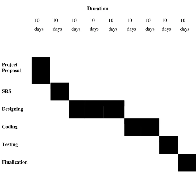
1.5 Project Schedule 1.5.1 Gantt Chart
Duration 10
days 10 days
10 days
10 days
10 days
10 days
10 days
10 days
10 days
Project Proposal
SRS
Designing
Coding
Testing
Finalization
Table 1.1: Gantt chart (Employee Transport System)
1.5.2 Release Plane/Milestone
Release 1: The following contents will be delivered during release 1- 1. Project CD
I. Project Demo II. User Manual 2. Documentation
Release 2: New feature will be added in next release.
CHAPTER-2
SOFTWARE REQUIREMENT SPECIFICATION
2.1 Functional Requirements
1. All the users have to register to the system.
2. Admin can modify the pick-up and drop off related services.
3. Admin can assign bus according to employee information.
4. Both admin and employee can send message to each other.
5. The system should allow employee to request a bus.
6. Admin will input bus route.
2.2 Non-Functional Requirement 1) Attractive User Interface.
2) User should change password in every 30days
2.3PerformanceRequirement
2.3.1 Speed and Latency Requirements
1. Information would be embed in MySQL database inside one second.
2. Query would reaction on schedule and bring the query result inside one second.
3. The User Interface of this framework is intended to load quicker but it will rely upon users device and internet speed.
4. If there are any approval mistake on the system, the mistake would visible inside one millisecond.
2.3.2 Precisions or Accuracy Requirements
1. After each effective login user would show the accurate information from the database.
2. No one can sing up or login without valid email.
3. Only the employee can request for the bus and the admin will approve it and assign the bus.
4. All the input field should insert exact and valid information to the database.
2.4Dependability Requirements 2.4.1 Reliability Requirements
1. Only authentic user can access to the system.
2. New user should register first with valid information.
3. Only admin can manage all user’s information.
2.4.2 Availability Requirements
1. Since it is a web application it is available everywhere on the internet
2. This application should run on any web related browser like Google Chrome, Firefox etc.
3. This application performs its operations quickly as per the client’s demand.
2.5Maintainability and supportability Requirements 2.5.1 Maintenance Requirements
1. Alter framework applications when its need to change on various condition.
2. Databases are used to maintain information in a systematic way.
3. Fixed bugs when the application will be corrupted or crash.
2.5.2 Supportability Requirements
1. The user will be provide a user manual with full documentation to make the application more effective.
2.6 Security Requirements 2.6.1 Access Requirements
1. Since the registration process will handle the admin of the company, no one other than the company's employer can access the system.
2. Administratorrecordwillbedefaultaccountswhichwillbeusableforinvestigatetheissue and notice the authenticate employees activity.
2.7 Usability and Human-Interactions Requirement 2.7.1 Ease of Use Requirements
1. User Interface of the application is user friendly and easy to use for all type of users.
2. The user manual is available for easy access to new users.
2.7.2 Understandability and Politeness Requirements 1. Admin account should be understandable to admin.
2. Employee account should be understandable to employee.
2.7.3 Accessibility Requirements
1. This is a web application so it can be accessed from any internet connected device.
2. Only after login, the user will be able to access his/her account.
CHAPTER-3 SYSTEMANALYSIS
3.1 Use Case Diagram
Figure 3.1: Use Case Diagram (Employee Transport System) [2]
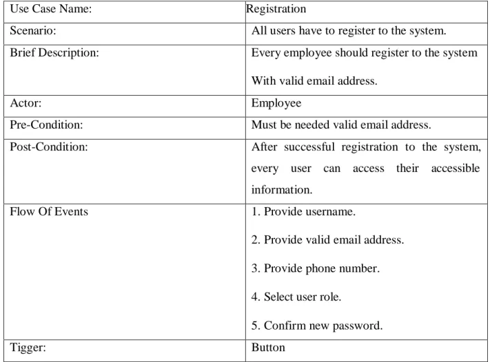
3.2 Use Case Description 3.2.1 Case 1: Registration
Use Case Name: Registration
Scenario: All users have to register to the system.
Brief Description: Every employee should register to the system
With valid email address.
Actor: Employee
Pre-Condition: Must be needed valid email address.
Post-Condition: After successful registration to the system, every user can access their accessible information.
Flow Of Events 1. Provide username.
2. Provide valid email address.
3. Provide phone number.
4. Select user role.
5. Confirm new password.
Tigger: Button
Table 3.1: User Registration (Employee Transport System)
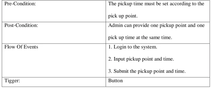
3.2.2 Case 2: Pick Up Point Management
Use Case Name: Pick Up Point Management
Scenario: Admin will input pick up point and time.
Brief Description: Admin will input the pickup points of all buses so that the employees can select their convenient pickup point to request a bus.
Actor: Admin
Pre-Condition: The pickup time must be set according to the pick up point.
Post-Condition: Admin can provide one pickup point and one
pick up time at the same time.
Flow Of Events 1. Login to the system.
2. Input pickup point and time.
3. Submit the pickup point and time.
Tigger: Button
Table 3.2: Pick Up Point Management (Employee Transport System)
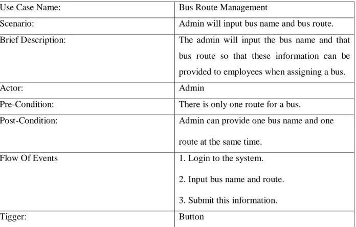
3.2.3 Case 3: Bus Route Management
Use Case Name: Bus Route Management
Scenario: Admin will input bus name and bus route.
Brief Description: The admin will input the bus name and that bus route so that these information can be provided to employees when assigning a bus.
Actor: Admin
Pre-Condition: There is only one route for a bus.
Post-Condition: Admin can provide one bus name and one
route at the same time.
Flow Of Events 1. Login to the system.
2. Input bus name and route.
3. Submit this information.
Tigger: Button
Table 3.3: Bus Route Management (Employee Transport System)
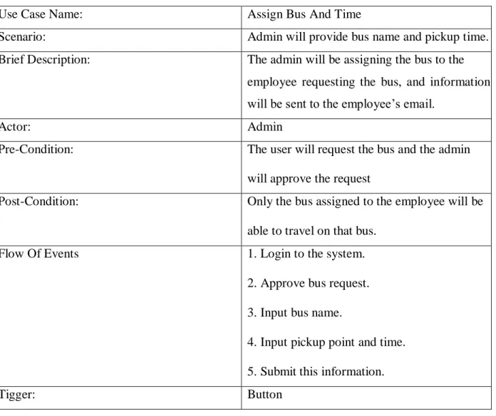
3.2.4 Case 4: Assign Bus and Time
Use Case Name: Assign Bus And Time
Scenario: Admin will provide bus name and pickup time.
Brief Description: The admin will be assigning the bus to the
employee requesting the bus, and information will be sent to the employee’s email.
Actor: Admin
Pre-Condition: The user will request the bus and the admin
will approve the request
Post-Condition: Only the bus assigned to the employee will be
able to travel on that bus.
Flow Of Events 1. Login to the system.
2. Approve bus request.
3. Input bus name.
4. Input pickup point and time.
5. Submit this information.
Tigger: Button
Table 3.4: Assign Bus and Time (Employee Transport System)
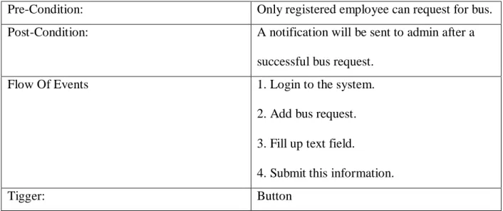
3.2.5 Case 5: Request Bus
Use Case Name: Request Bus
Scenario: Employee will request for bus.
Brief Description: To request a bus employee have to add their name, email and pick up information in bus request option.
Actor: Employee
Pre-Condition: Only registered employee can request for bus.
Post-Condition: A notification will be sent to admin after a
successful bus request.
Flow Of Events 1. Login to the system.
2. Add bus request.
3. Fill up text field.
4. Submit this information.
Tigger: Button
Table 3.5: Request Bus (Employee Transport System)
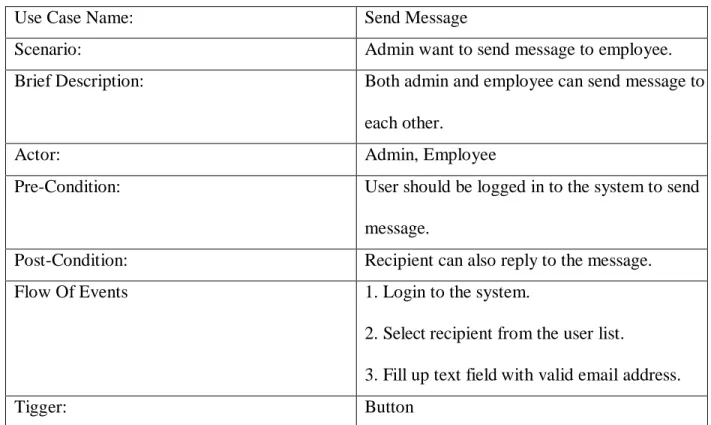
3.2.6 Case 6: Send Message
Use Case Name: Send Message
Scenario: Admin want to send message to employee.
Brief Description: Both admin and employee can send message to
each other.
Actor: Admin, Employee
Pre-Condition: User should be logged in to the system to send
message.
Post-Condition: Recipient can also reply to the message.
Flow Of Events 1. Login to the system.
2. Select recipient from the user list.
3. Fill up text field with valid email address.
Tigger: Button
Table 3.6: Send Message (Employee Transport System)
3.3 Activity Diagram
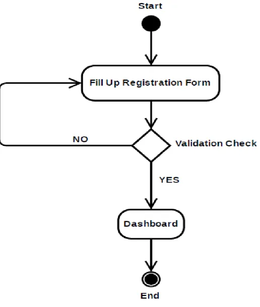
3.3.1 Activity diagram for registration
All user should register to the system to use system. To register all user should provide their valid information. Then admin will complete the registration process. [2]
Figure 3.2: Activity diagram for registration (Employee Transport System)
3.3.2 Activity diagram for Pickup Point Management
Only admin can set pick up information. First admin has to login to the system.
Then he/she will open the pick-up page and will fill up all information required. [2]
Figure 3.3: Activity diagram for Pick up Point Management (Employee Transport System)
3.3.3 Activity diagram for Bus Route Management
Only admin can set bus route according to bus number. Admin has to login to system to set bus route. Admin will select bus route option and then he will input bus route information. [2]
Figure 3.4: Activity diagram for Bus Route Management (Employee Transport System)
3.3.4 Activity diagram for Request Bus
Employee will request for bus. First employee have to login to the system. Employee request bus from bus request option and have to provide valid information to request bus. [2]
Figure 3.5: Activity diagram for Request Bus (Employee Transport System)
3.3.5 Activity diagram for Send Message
All user can send message to each other. To send message user has to log in to the system. Then they will select user from user list whom they want to send message and will write message to send it. [2]
Figure 3.6: Activity diagram for Send Message (Employee Transport System)
3.3.6 Activity diagram for Assign Bus and Time
Only admin can assign bus to employee. Employee will request bus and admin will approve or denyit.Employeewillrequestbususingrequiredinformationandwillsendit.Adminwillseethe request and if approve the request he will assign a bus to the employee. [2]
Figure 3.7: Activity diagram for Assign Bus and Time (Employee Transport System)
3.4 Sequence Diagram
3.4.1 Sequence diagram for Registration
Figure 3.8: Sequence diagram for Registration (Employee Transport System) [2]
3.4.2 Sequence diagram for Pickup Point Management
Figure 3.9: Sequence diagram for Pick up Point Management (Employee Transport System) [2]
3.4.3 Sequence diagram for Bus Route Management
Figure 3.10: Sequence diagram for Bus Route Management (Employee Transport System) [2]
3.4.4 Sequence diagram for Request Bus
Figure 3.11: Sequence diagram for Request Bus (Employee Transport System) [2]
3.4.5 Sequence diagram for Send Message
Figure 3.12: Sequence diagram for Send Message (Employee Transport System) [2]
3.4.6 Sequence diagram for Assign Bus and Time
Figure 3.13: Sequence diagram for Assign Bus and Time (Employee Transport System) [2]
CHAPTER-4
SYSTEM DESIGNSPECIFICATION
4.1 Class Diagram
Figure 4.1: Class Diagram (Employee Transport System) [2] [3]
4.2 Entity Relationship Diagram
Figure 4.2: Entity Relationship Diagram (Employee Transport System) [1]
4.3 Development Tools and Technology
4.3.1 User Interface Technology 1. HTML5
2. CSS3 3. Bootstrap4 4. jQuery
5. Brackets Editor
4.3.2 Implementation Tools and Platforms 6. PHP7
7. LARAVEL Framework5.6 8. MySQL Database
9. Atom 10. XAMPP
CHAPTER-5 SYSTEMTESTING
5.1 Testing Feature 5.1.1 Features to be tested
1. User Registration 2. Login
3. Request Bus 4. Send message
5.1.2 Features not to be tested 1. Bus route
2. Approve Request 3. Pick up information
5.2 Testing Strategies 5.2.1 Test Approach
1. The entire framework will be tried manually.
2. The framework testing dependent on client acceptancy.
5.2.2 Test Criteria
1. Integration –The test will pass if the case fulfill the requirements of the case design architecture, if not then it will fail.
2. Component - The test will pass if the case satisfy the necessities of the case structure requirement, if not then it will fall through.
3. System-Thetestwillpassifthecasesatisfythefunctionalandnon-functionalrequirement, if not then it will fall through.
5.2.3 Suspension and Resumption
1. Acceptance Testing - This test will viewed as passed if each build is fruitful this test will viewed as passed if each build is successful.
2. Regression testing - if any change occurs in the system the system will work properly.
3. System Design Testing – if any change happens in the system user interface the system will work properly.
5.2.4 Testing Schedule
Test Phase Time Tested By
Test Plan Creation 7 days Md. Shohel Rana
Test Specification Creation 7 days Md. Shohel Rana
Test Specification Team Review 10 days Md. Shohel Rana
Component Testing 10 days Md. Shohel Rana
Integration Testing 10 days Md. Shohel Rana
System Testing 15 days Md. Shohel Rana
Table 5.1: Testing Schedule (Employee Transport System)
5.3 Test Cases
5.3.1 Test Case1: Registration
Test Case:1 Test Case Name: Registration
System: Employee Transport System Subsystem: N/A
Designed By: Shohel Executed By: Shohel
Pre-Condition: Must be needed valid email address.
Step Action Expected Result Pass/Fail Comment
1. When a user does not fill- up any field.
All fields are required. Pass All fields are required.
2. When a user fill up only one field and check register.
Others fields are required. Pass Others fields are required.
3. When a user give an email without domain name.
The email must be a valid email address.
Pass Required valid
email address.
4. When a user fill-up email
field as
like:example
@gmail.com
The system should accept this email as valid email address.
Pass This is valid email address.
5. When a user try to register by previously used email.
This email is already used.
Pass Email must be
unique.
6. When a user input phone number as character.
This system should display phone number must be a number.
Pass Phone number
must be a number.
7. When a user fill-up password field less than6 character.
This system should display password must be 6 character.
Pass Password must be 6character.
8. If password and confirm password is not same.
The password
confirmation dose not match.
Pass Password
confirmation dose not match.
9. When a user submit registration form without user role.
This system should display please select user role.
Pass Select user role.
10. When a user try to register by previously used phone number.
This phone number is already used.
Pass Phone number
must be unique.
Table 5.2: Test Case Name: Registration (Employee Transport System)
5.3.2 Test Case2: Log in
Test Case:2 Test Case Name: Log in
System: Employee Transport System Subsystem: N/A
Designed By: Shohel Executed By: Shohel
Pre-Condition: User should be log in with valid email address and password.
Step Action Expected Result Pass/Fail Comment
1. When a user does not fill- up any field.
All fields are required. Pass All fields are required.
2. When a user fill up only one field and press submit.
Others fields are required. Pass Others fields are required.
3. When a user give an email without domain name.
The email must be a valid email address.
Pass Required valid
email address.
4. When a user input valid
email but wrong
password.
The system should display password is incorrect.
Pass Password is
incorrect.
5. When a user input invalid email but correct password.
The system should display this email is invalid.
Pass Required valid
email address.
6. When a user input valid email and correct password.
The user successfully access their own dashboard.
Pass Login success.
Table 5.3: Test Case Name: Log in (Employee Transport System)
5.3.3 Test Case 3: Request Bus
Test Case:3 Test Case Name: Request Bus
System: Employee Transport System Subsystem: N/A
Designed By: Shohel Executed By: Shohel
Pre-Condition: Only registered employee can request for bus.
Step Action Expected Result Pass/Fail Comment
1. When a user does not fill- up any field.
All fields are required. Pass All fields are required.
2. When a user fill up only one field and check register.
Others fields are required. Pass Others fields are required.
3. When a user give an email without domain name.
The email must be a valid email address.
Pass Required valid
email address.
4. When a user fill up all field with email of the logged in employee.
Bus request information successfully inserted.
Pass Request
successful.
Table 5.4: Test Case Name: Request Bus (Employee Transport System)
5.3.4 Test Case 4: Send Message
Test Case:4 Test Case Name: Send message
System: Employee Transport System Subsystem: N/A
Designed By: Shohel Executed By: Shohel
Pre-Condition: User should be logged in to the system to send message.
Step Action Expected Result Pass/Fail Comment
1. Admin select employee to send message.
The system should display a message form to send message.
Pass One message can send at a time.
2. User send message without fill up any field
A message will be shown must be fill up all field.
Pass Message
can’t empty.
field
3. When a user fill up only one field and press submit.
Others fields are required. Pass Others fields required.
are
4. When a
message user role.
user form
submit without
This system should display please select user role.
Pass Select user role.
Table 5.5: Test Case Name: Send Message (Employee Transport System)
CHAPTER-6 USER MANUAL
6.1 User Manual 6.1.1 Homepage
This is the home page of Employee Transport System.
6.1.2 User registration
In this page user will fill up registration form. All new user have to register to the system for the first time.
6.1.3 Log in
This is the log in page of the system.User have to provide email address and password to log in.
6.1.4 Dashboard
In this page user can monitor his/her all the activities in the system.
6.1.5 All user
In this page admin can view all user information. Admin can also approve or reject user. User can be deleted from the system by the admin.
6.1.6 Pick Up point
Here user can view all pick information.
6.1.6 Add Pick Up information
In this page user can add his/her pick up information so that employee can be picked up by the transport from the spot everyday.
6.1.7 Bus route information
In this page admin can view all bus route according to bus number.
6.1.8 Input bus route
Here admin can add bus name and bus route.
6.1.9 All bus request
In this page admin can see all the pending request. Admin can also approve or deny bus request from this page.
6.1.10 Assign bus
From this page admin will assign bus to the employee who requested for bus. Admin will assign bus with bus name and pick up point specificly.
6.1.11 Bus request
In this page employee can request for bus to the admin. Employee will select his/ her preferable pick up point while requesting for bus.
CHAPTER-7 PROJECTSUMMERY
7.1 GitHub Link
Http:
7.2 Critical Evaluation
The present era is the age of technology. In this age, technology is progressing very fast and with thisfastsomelimitationsareaddedtomysystem.Newtechnologiesofthepresenteracanbeused to make this system more efficient and user friendly as per the demands of the user.
7.3 Obstacles and Achievements
Technology is evolving day by day with the passage of time. Therefore, LARAVEL Framework is improving day by day. New features are being added on a regular basis like various package, library function etc. So working with this new feature is a bit difficult but not impossible. In the meantime, it is hoped that this system will meet the important needs of a company and its employees. This will eliminate the pain of the employees not being able to come to the office in time.
7.4 Future Scope
There is an option to add some new features to each system to meet future user needs. So this system also has a few features to add in the future. For example:
1. The system will have the option of arrange the vehicles and employee who are managing those vehicles.
2. Employees will see the current location of the vehicle on Google Maps.
Therearemanyfeaturesthatcanbeaddedtothisprojectthatcannotbedevelopedbyanindividual.
CONCLUSIONS
Although I built this system (Employee Bus Transport System), there are many limitations. I have attempted my best to overcome my limitations. This system will provide better service to the employees of a company so that employees can get to the office at the right time. Basically, the system will provide transport services to such employees on the one hand, and increase the value of the company on the other.
APPENDIX
May include any supporting material which isn't basic for the principle body of the report. These could be-
1. User manual or guide 2. Tables
3. Details requirements 4. Project literature review 5. Diagrams
6. Test plan and results
REFERENCES
[1]. Entity Relationship diagram [Access on 10 October 2019 12:10 am] Link:
https://erdplus.com/documents
[2]. Use Case Diagram, Activity Diagram, Sequence Diagram, Class Diagram, Block Diagram [Access on 12 September 2019 01:45 am]
Link: https://online.visual-paradigm.com/w/wfarmhgh/drive/#diagramlist:proj=0&open
[3]. Developing Software with UML Author: Bernd Oestereich [Second Edition] Chapter 5, Section 5.3 Class, Diagrams (Relational Elements), Page. 219
[4] Literature review [Access on 11 August 2019 2.11am]
https://zapier.com/learn/forms-surveys/design-analyze-survey/
![Figure 1.1: Block Diagram (Employee Transport System) [2]](https://thumb-ap.123doks.com/thumbv2/filepdfnet/10791488.0/16.918.165.766.188.849/figure-1-1-block-diagram-employee-transport-system.webp)
![Figure 3.1: Use Case Diagram (Employee Transport System) [2]](https://thumb-ap.123doks.com/thumbv2/filepdfnet/10791488.0/24.918.113.806.179.809/figure-3-use-case-diagram-employee-transport-system.webp)