On the theoretical possibility to apply an acoustic diffraction
grating as a complex frequency filter device for electronic signals
Nico F. Declercq
a,*, Joris Degrieck
a, Oswald Leroy
baSoete Laboratory, Department of Mechanical Construction and Production, Ghent University, Sint Pietersnieuwstraat 41, B-9000 Ghent, Belgium bInterdisciplinary Research Center, Katholieke Universiteit Leuven Campus Kortrijk, E. Sabbelaan 53, B-8500 Kortrijk, Belgium
Received 11 March 2004; accepted 8 April 2005 Available online 3 May 2005
Abstract
In electronics, it is well known that filtering devices can be made that are able to decompose a signal instantaneously into a num-ber of real frequency components. This procedure is equivalent to a numerical real time Fourier transform. However, it is also known that an electronic signal can be decomposed not just in real frequency components, but also in complex frequency compo-nents. The current paper shows that it is theoretically possible to create a device, made of a periodically rough surface and a system that transforms the electronic signal into acoustic waves, that can be used to measure the amplitude attributed to considered com-plex frequency components of an electronic signal, in real time. ThisÔthought deviceÕis mainly based on the directivity of diffracted sound and the complex frequency dependence of this directivity.
Ó2005 Elsevier B.V. All rights reserved.
Keywords: Complex harmonic waves; Diffraction; Transient waves; Inhomogeneous waves; Corrugated surfaces; Acousto-optics
1. Introduction
From an old paper of Spitzenogle and Quazi[1]it can be learned that aÔtime limited signalÕcan be decomposed into a summation of signals with exponentially varying amplitude as a function of time. This principle has later been translated [2] to space limited acoustic signals (bounded beams) and appeared to be excellent in explaining what happens to sound at the Rayleigh angle of incidence. The latter formed a strong impetus for the development of the inhomogeneous wave theory, which explains the behavior of plane waves having complex parameters. Lately, special attention was drawn on the case of inhomogeneous waves having complex frequency [3–6]. Such complex harmonic plane waves therefore
re-turn the inhomogeneous wave theory back to the paper of Spitzenogle and Quazi[1]. In acoustics, complex har-monic waves are building blocks of sound beams, bounded in space and in time. In electronics, signals are often not really bounded in time. However one is fre-quently interested in the instant properties of such sig-nals. For that reason, a numerical spectrogram can be obtained that gives the amplitude as a function of the real frequency and as a function of time. An experimen-tal spectrogram can also be formed (with some errors) in real time by an electronic filter system. Nevertheless, it may likewise be important to consider a ÔspectrogramÕ of a signal not just in the real frequency space, but also in the more general complex frequency space. This is mathematically reachable within a time limited window [1], but it must also be possible to build a device that performs such a spectrogram in real time somehow by means of a filter system. In what follows, it is shown from a theoretical point of view, that an acoustic diffrac-tion grating is a possible tool for that purpose.
0041-624X/$ - see front matter Ó2005 Elsevier B.V. All rights reserved.
doi:10.1016/j.ultras.2005.04.002
* Corresponding author. Tel.: +32 9 264 3436; fax: +32 9 264 3587.
E-mail addresses: [email protected], [email protected]
(N.F. Declercq).
2. Complex harmonic plane waves
A thorough description of complex harmonic plane waves can be found in[3–6]. Therefore, we make this dis-course very short. Complex harmonic plane waves are described by a particle displacement vectoruas follows:
u¼APexpðikrixtÞ ð1Þ
Besides timetand spacer, all parameters in(1), i.e. the amplitudeA, the polarizationP, the wave vectorkand the angular frequencyx can be complex valued.
Com-plex harmonic plane waves differ from harmonic plane waves by an angular frequencyxthat is complex valued
instead of real valued. Hence,
x¼x1þix2; x1
;x22R ð2Þ
and
uðr¼0;tÞ ¼APexpðx2tÞexp iðx1tÞ ð3Þ
Henceforth, the term ÔfrequencyÕ denotes x/(2p) while
the term angular frequency will be specifically used for
xitself. It is seen in(3)that the amplitude changes
expo-nentially in time, through x2. For consistency with
Ref.[1], we only considerx1P0 andx2P0. Complex harmonic waves are a solution of the visco-elastic wave equation if the dispersion relation holds[6]:
kk¼ x
v0ia0
2
ð4Þ
withv0the phase velocity of plane waves having a real wave vector and real frequency and witha0the intrinsic
damping of the considered media.
Important for what follows is the definition of the en-ergy velocity vectorvE. It can be found in[3,4,6]thatvE
3. The diffraction of complex harmonic plane waves
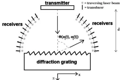
When harmonic plane waves, possessing a wave vec-tor component kincx along the interface, interact with a corrugated surface (seeFig. 1), having a periodicity K,
they diffract into harmonic plane waves of different orders ÔmÕ. Each of these waves have a wave vector component
kmx ¼kincx þm2
p
K ð6Þ
along the interface and a componentkm
z perpendicular to the interface given by the dispersion relation(4). It has been shown before that this grating equation(6)is also valid for incident inhomogeneous waves. This is because
it represents the spatial periodicity of the phase along the periodic interface and not the amplitude. Because the imaginary part of the frequency, of a given incident sound wave, influences the amplitude and not the phase, it is evident that the grating equation(6) also holds for incident complex harmonic plane waves.
For a given diffraction order ÔmÕand its wave vector componentkm
x along the interface, the sign of the wave vector component km
z normal to the interface is chosen according to well known sign choice conventions [7– 10] in terms of the phase propagation direction, based on causality principles, interpreted here in terms of the energy propagation direction.
4. How the acoustic diffraction grating may work
The dispersion relation(4) represents two real equa-tions, whereas the propagation of a complex harmonic plane wave is characterized by two unknown vectors,
k1andk2, and two unknown scalars, x1andx2. For a chosen Euclidian space, the grating equation and inci-dent wave propagation direction determine one vector component (in 2D space) or two vector components (in 3D space) of bothk1andk2. This means that in order to be identified, there must be two independent para-meters quantified, for examplex1andx2, or for
exam-ple two independent quantities that contain unambiguous information aboutk1andk2.
In what follows, we show numerically that, under the right conditions, the direction of the energy velocity vec-torvEas well as the direction of the phase velocity vector can be applied for that purpose, because for a given direction of the energy velocity vectorvE as well as the direction of the phase velocity vector, a unique couple (x1,x2) exists.
Consider an electronic signals(t) that is decomposed into a series of complex frequency signals, i.e.
sðtÞ ¼X
n
FnðtÞexpðiXnðtÞtÞ ð7Þ
Within a time limited interval around a certaint0, a rep-resentation is possible with constant Sn=Fn(t0) and transmitted to a transducer (emitter) perpendicularly di-rected to a diffraction grating at a distance d. If for a moment the diffraction grating is not considered, then a receiver at distance 2dwill receive the acoustic signal and will transform it again into an electronic signal. This output signal will differ from the input signal because the system signal > transducer > propagation medium > transducer > signal has a transfer characteristic different from unity. Hence, the output signal Sout is related to the input signalSinas follows:
Sout¼TðSinÞ ð9Þ
in which T is an operator who changes the amplitude attributed to each complex frequency component in the signal. If there is a grating and if the receiving trans-ducer (see short bold lines inFig. 1) is placed at a dis-tance d from the surface at a certain direction, then there will also a transfer operatorRbe involved, which corresponds to the reflection coefficient for the received reflected order.
Therefore, the received signal is ultimately described by
As a consequence, ifRandTare known for each possi-blexn, then measuringRTSnreveals the values ofSn, i.e.
the problem is reduced to measuringRTSnas a function of each required xn. Therefore, the problem is reduced
to defining what experimental ÔconditionÕ corresponds with each xnand measuring the accompanying
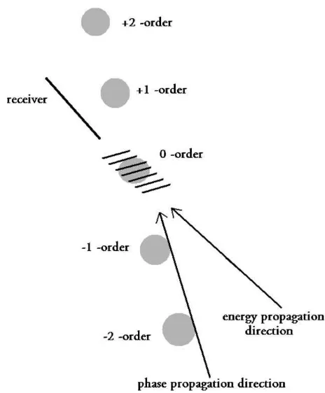
ampli-tude for each of those ÔconditionsÕ. In what follows, it will be shown that measuring the phase propagation direction together with the energy propagation direc-tion, defines a unique ÔconditionÕ. The energy propa-gation direction can practically be determined by a classical omni-directional transducer, whereas the phase propagation direction can be determined by the diffrac-tion of laser light. The first is possible because an omni-directional transducer at a given spot measures by definition the encountered sound intensity, whereas the latter is possible because sound forms a diffraction grat-ing for laser light and diffracts a laser light beam into different diffraction orders perpendicular to the sound
wave fronts. This is the basic principle of acousto-optics. Both principles are depicted inFig. 2, where gray circu-lar areas denote a cross section of a (diffracted) laser beam and where again the bold line represents the recei-ver. The set of short parallel lines inFig. 2represent the wave fronts. The energy propagation direction and the phase propagation direction are denoted by a long arrow.
5. Numerical simulations
As explained, measuring the amplitude correspond-ing to a certain phase propagation direction and energy propagation direction, reveals the magnitude of a parti-cular complex frequency component of a signal. There is however a limitation. When sound is received at a cer-tain angle, it can only be attributed for cercer-tain to an order ÔmÕif there is no interference possible with other diffraction orders. Hence, a complex frequency spectro-gram is solely possible within a certain interval in which there is no confusion possible between different diffrac-tion orders. For that purpose the grating periodicity must be so that the maximum considered real frequency corresponds to the critical frequency for second order reflected waves. This critical frequency is defined as the largest frequency for which the second order
flected wave is evanescent (i.e. sticking to the interface). Practically this corresponds to the second order Scholte– Stoneley wave generating frequency, see for example Refs. [7,8]. The lowest frequency under consideration is then the critical frequency for first order waves, i.e. the first order Scholte–Stoneley wave generating fre-quency, because below this frefre-quency, except for zero order reflected sound, there is no sound reflected from the interface.
We consider a periodically corrugated interface between water and a solid. The density of water is 1000 kg/m3, the plane wave velocity in water is 1480 m/s and the periodicity of the corrugation is K=
250lm. For simplicity, we have only considered zero intrinsic damping. InFig. 3, the calculated phase prop-agation direction (here equal to the energy propprop-agation direction) is depicted for normal incident harmonic homogeneous plane waves having real frequencies be-tween 4 MHz and 16 MHz. The dotted line corresponds to the first order reflected plane waves, whereas the solid line corresponds to second order reflected plane waves. The critical frequencies mentioned above, are directly visible as the frequencies at which the propagation direc-tion starts to deviate from 90°, measured from the nor-mal to the interface. Note that between approximately 6 MHz and 12 MHz there are only bulk reflected waves of the first order. This is the frequency region that we will focus on here in order to avoid interference be-tween second and first order reflected sound waves. A Ôthought deviceÕ, as considered here, will therefore only be able to filter between a limited frequency interval, i.e. between 6 MHz and 12 MHz. Whenever necessary, this interval can be changed by using another grating periodicity.
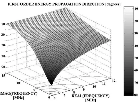
In Fig. 4 respectively Fig. 5, the phase propagation direction and energy propagation direction are depicted as a function of the real and imaginary frequency. Com-parison of these figures reveals, that for every couple (x1,x2) within the considered interval, there is one
en-ergy propagation direction and there is one phase prop-agation direction. Furthermore, note that the projected equi-amplitude lines of one figure do not intersect more than once the projected lines in the other figure and therefore, for every combination of an energy propaga-tion direcpropaga-tion and a phase propagapropaga-tion direcpropaga-tion, there corresponds only one couple (x1,x2). This shows
Fig. 3. The phase propagation direction for first and second order reflected sound coming from normal incident harmonic sound at different real frequencies. Dotted line: first order, solid line: second order.
Fig. 4. The first order phase propagation direction as a function of the complex frequency for normal incident sound. The lines on the horizontal surface are projected equi-amplitude lines.
Fig. 5. The first order energy propagation direction as a function of the complex frequency for normal incident sound. The lines on the horizontal surface are projected equi-amplitude lines. Comparison of
numerically that there is aÔone to oneÕrelation between the measurable quantities and (x1,x2). In other words,
if the phase propagation direction and the energy propa-gation direction are measured instantaneously, together with the amplitude of the received sound, the complex frequency and its attributed amplitude are found.
6. Conclusions
It is recalled that a time varying electronic signal can be decomposed not just into real frequencies, but also into complex frequencies. The first method can be per-formed electronically by means of a filtering device. The second is more difficult. Here we have theoretically proposed a method based on a diffraction grating to-gether with the use of omni-directional transducers and the diffraction of laser light. The basic principle is the fact that for each complex frequency there is a unique couple of energy propagation and phase propa-gation direction.
Acknowledgments
The authors are indebted to ÔThe Flemish Institute for the Promotion of the Scientific and Technological Research in Industry (I.W.T.)Õ and NATO (PST.NR. CLG.980315) for financial support.
References
[1] F.R. Spitzenogle, A.H. Quazi, Representation and analysis of time-limited signals using a complex exponential algorithm, J. Acoust. Soc. Am. 47 (5) (1970) 1150–1155.
[2] J.M. Claeys, O. Leroy, Reflection and transmission of bounded sound beams on half-spaces and through plates, J. Acoust. Soc. Am. 72 (2) (1982) 585–590.
[3] M. Deschamps, B. Poiree, O. Poncelet, Energy velocity of complex harmonic plane waves in viscous fluids, Wave Motion 25 (1997) 51–60.
[4] O. Poncelet, M. Deschamps, Lamb waves generated by complex harmonic inhomogeneous plane waves, J. Acoust. Soc. Am. 102 (1) (1997) 292–300.
[5] A. Bernard, M. Deschamps, M.J.S. Lowe, Comparison between the dispersion curves calculated in complex frequency and the minima of the reflection coefficients for an embedded layer, J. Acoust. Soc. Am. 107 (2) (2000) 793–800.
[6] F. Declercq, R. Briers, J. Degrieck, O. Leroy, The history and properties of ultrasonic inhomogeneous waves, IEEE-UFFC, in press.
[7] J.M. Claeys, O. Leroy, A. Jungman, L. Adler, Diffraction of ultrasonic waves from periodically rough liquid–solid surface, J. Appl. Phys. 54 (10) (1983) 5657–5662.
[8] K. Mampaert, P.B. Nagy, O. Leroy, L. Adler, A. Jungman, G. Quentin, On the origin of the anomalies in the reflected ultrasonic spectra from periodic surfaces, J. Acoust. Soc. Am. 86 (1) (1989) 429–431.
[9] K.E.-A. Van Den Abeele, R. Briers, O. Leroy, Inhomogeneous plane-wave scattering and mode stimulation on periodic rough surfaces, J. Acoust. Soc. Am. 99 (5) (1996) 2883–2897.