PLC INTERFACING USING VISUAL BASIC
MOHD HERMAN BIN MOHD ARIS
PLC INTERFACING USING VISUAL BASIC
MOHD HERMAN BIN MOHD ARIS
This Report Is Submitted In Partial Fulfillment Of Requirements For The Degree Of
Bachelor of Electrical Engineering
(Control, Instrumentation & Automation)
Faculty of Electrical Engineering
Universiti Teknikal Malaysia Melaka
DECLARATION
“I hereby declared that this report is a result of my own work except the excerpts that
have been cited clearly in the references.”
Signature : ---
APPRECIATION
---
Alhamdulillah, grateful to Allah S.W.T with Allah blessing I manage to finish
my research and development of my Bachelor Degree Project 2 and final report for
my Bachelor Degree Project 2 (PSM 2).
I would like to thank you especially to my beloved family for their unending
support since I studying in UTeM. My PSM supervisor En. Aminuddin b. Aman, and
all UTeM member & friends for all the support and help that has given.
Lastly, I also would like to thank you to all the people that involve directly or
PROJECT ASBTRACT
The usage of Graphical User Interface in industrial has become wider. The
most commen usage of GUI is as communication between PLC and PC. Without
using supplier provided software, a GUI project has been developed. The project is
about designing and developing an interfacing system for a PLC process. It includes
researches and learning about the things which is related to the system. Basically the
system is designed due to the widely usage of PLC nowdays. Upon completing the
system, Visual Basic is used as the programming tool for the interface while a
parallel port is used as the communication between PC and PLC in order to send and
receive data. The functions of the system is to simulate and control a PLC process.
Within this system, it provides an optional to reconfigure the PLC process such as
the process delay, process sequence and others. Besides that the project is also to
creat a specific interfacing system for a specific PLC process such as the traffic light
system and material mixer tank system. In overall, the project provides an alternative
ABSTRAK PROJEK
Penggunaan Pengantaramuka Grafik Pengguna menjadi semakin meluas di
industri. Penggunaan utama GUI di industri adalah sebagai komunikasi di antara PC
dan PLC. Tanpa menggunakan perisian yang dibekalkan oleh pembekal PLC, satu
projek Pengantaramuka Grafik Pengguna dibangunkan. Projek ini adalah berkaitan
dengan merekacipta dan menghasilkan satu sistem antaramuka untuk satu proses
PLC. Ianya merangkumi kajian dan pembelajaran mengenaik perkara-perkara yang
berkaitan dengan sistem tersebut. Secara amnya, sistem ini dibina kerana
penggunaan PLC yang meluas pada masa kini. Di dalam melaksanakan projek ini,
perisaian Visual Basic digunakan sebagai alat untuk memprogram antaramuka
tersebut. Sementara itu, pengkalan selari digunakan sebagai talian perhubungan di
antara komputer dan PLC. Fungsi utama sistem ini adalah untuk mensimulasi dan
mengawal proses PLC. Sistem ini juga menyediakan pilihan untuk mengatur semula
proses-proses PLC seperti tundaan proses, urutan proses dan lain-lain. Selain
daripada itu, projek ini juga bertujuan untuk menghasilkan satu sistem antaramuka
yang khusus untuk sesuatu proses PLC sebagai contoh sistem lampu isyarat dan
sistem tangki pengadun bahan mentah. Secara keseluruhannya, untuk menghasilkan
satu alternatif bagi menggantikan penggunaan PLC ’ladder diagram’ sebagai
TABLE OF CONTENT
CHAPTER CONTENT PAGE
APPRECIATION iii
PROJECT ASBTRACT iv
ABSTRAK PROJEK v
TABLE OF CONTENT vi
LIST OF FIGURE x
LIST OF TABLE xi
1 INTRODUCTION
1.1 Introduction 1
1.2 Project Overview 2
1.3 Problem Statements 2
1.4 Project Objectives 2
1.5 Project Scope 3
1.6 Project Report Outlines 3
2 BACKGROUND STUDY
2.1 Vijeo Designer Review 5
2.2 Interface Overview 8
2.2.2 User Interface 10
2.2.3 Precursors to Graphical User Interfaces 10
2.2.4 PARC User Interface 11
2.3 Evolution of Graphic User Interface 11
2.3.1 Graphical User Interface design 12
2.3.2 Zooming user interface 12
2.3.3 Graphical User Interfaces Compared to Command 13
Line Interfaces
2.4 Parallel Port Overview 14
2.5 Programmable Logic Control Overview 15
2.5.1 PLC User Interface 16
2.5.2 PLC Communications 16
2.5.3 PLC Compared with other Control Systems 17
2.5.4 PLC Digital and Analog Signals 18
2.6 Visual Basic Overview 18
4.2.1 Material Mixer Tank System Operation 24
4.3 Software Development 25
4.3.1 GUI Software Selection 25
4.3.2 Visual Basic Parallel Port Programming Theory 27
4.3.3 Parallel port address 30
4.3.4 Sending Visual Basic Output 31
4.4 Software Implementation 32
4.4.1 Inpout.dll Testing 34
4.4.2 Designing the Graphical User Interface 34
4.4.3 Programming the Graphical User Interface 35
4.5 Hardware Development 36
4.6 Hardware Implementation 37
4.6.1 PC to PLC GUI Communication 38
4.6.1.1 Circuit Operation 39
4.6.2 ULN2803 circuit 39
4.6.3 Relay Control Circuit 40
4.6.4 16 to 4 Encoder circuit 41
5.3.1 Parallel Port Interfacing Circuit 49
REFERENCES 55
APPENDIX A Visual Basic programming code for Inpout.dll testing 56
APPENDIX B Material Mixer Tank GUI coding 57
LIST OF FIGURE
FIGURE TITLE PAGE
2.1 Communication Setting Between PLC and HMI 6
2.2 This is an Example Project Using Vijeo-Designer 7
2.3 Original 1984 Mac OS desktop 11
2.4 Schematic of PLC 16
3.1 Project flowchart 21
4.1 Omron CQM1H-CPU21 23
4.2 Designing the PLC process. 24
4.3 Parallel port specification. 28
4.4 Steps to paste the inpout32.dll file. 29
4.5 Parallel port I/O address 30
4.6 Software implementation Flow chart 33
4.7 Simple LED driving circuit 33
4.8 Inpout.dll testing 34
4.9 Designing the GUI 35
4.10 Programming the GUI 36
4.11 Interfacing system block diagram 37
4.12 Hardware development flow chart 38
4.13 ULN2803 circuit 40
4.14 Relay Control Circuit 41
4.15 16 to 4 Encoder Circuit 42
5.1 Material Mixer Tank Ladder Diagram 44
5.2 The first form of the GUI 45
5.3 Changing the background color 46
5.4 Selecting background color 46
5.6 GUI displays the selected sequence and quantity 48
5.7 Breakdown situation. 49
LIST OF TABLE
TABLE TITLE PAGE
1 The SSP definitions 15
2 Basic characteristics of the most popular 26
programming software
3 Parallel port pin assignment 28
4 Parallel port data pins conditions 31
CHAPTER 1
INTRODUCTION
1.1 Introduction
Nowadays, advanced technology has led into the variation of hardware and
software solutions that often need in automation technology. From the extremely
development in automation technology field, PLC has been introduced as a device to
control machinery on factory assembly lines. PLC has made the industrial process
more productive and effective. Therefore the usage and requirement upon PLC
become wide and increased. As a respond with the development, many experts have
made their research on how to come out with more benefits from PLC. As a result of
the researches, they found out the alternative way to communicate PLC and PC
where they called Human Machine Interface (HMI).
HMI technology is defined as the application of software or hardware that
allows a user to interact with their plant equipment. With the HMI technology, a user
will have the ability to control their plant equipment functions from a single personal
computer platform. All the equipments operations and functions for manufacturing a
product are easily controlled by a click of the mouse. In the past 10-years, HMI has
become very graphical and today, HMI technology in many instances animates the
manufacturing process on computer displays. As an elaboration on the HMI,
Graphic User Interface (GUI) has been developed. Where, the basic function is to
communicate with PLC, display and store data from machine process and control the
machine process. From the GUI, the users or plant operators are alerted to machinery
and process problems from visual and audio alarms that prevent potential problems
1.2 Project Overview
The project is to implement the Graphic User Interface for a PLC process. It
includes design of GUI and a material mixer tank as the PLC application. The most
important things in this project are the use of visual basic 6.0 as programming tool
for the GUI, Omron PLC and the parallel port as the medium of communication
between PC and PLC. This project is divided into two sections, which are software
and hardware development and controlling PLC application.
1.3 Problem Statement
The usage of PLC in automation industry has been wider nowadays. With
PLC as the machine controller in the production assembly lines, it has increase the
production and quality. However, even within the most advanced technology there
will be a time that something unpredictable occurred. Where, machine breakdown is
the most unwanted things. The longer the breakdown is, the longer it will affect the
production lines. A way to reduce the breakdown duration is to display the machine
process or PLC process where we can easily see the breakdown situations or parts.
PLC ladder diagram display often use as the display of PLC process. However the
display of ladder diagram is complex and not systematic. Therefore, the purpose of
this project is to design a GUI that suitable to replace the ladder diagram display. It
also can facilitate the process of reconfiguring and troubleshooting. Within this
condition the breakdown duration will be decreased and production will improved.
1.4 Project Objectives
There are four objectives of this project, which is stated in the following
texts:
1. To design an develop PLC Graphical User Interface (GUI).
2. To simulate a PLC process using the Graphical User Interface.
3. To design and develop communication between PC and PLC.
1.5 Project Scope
In general, all projects have their own scope or limitation as a
guideline. After several discussions with supervisor I have come out with the
scope that appropriate to complete this project. Therefore the project scope
for implementation this project is:
I. Design and develop the complete Graphical User Interface (GUI)
for a PLC process using visual basic 6.0 software.
II. Simulate an Omron PLC process using the Graphical User Interface
(GUI).
III. Design and develop communication between PC and PLC using PC
parallel port.
IV. Control an Omron PLC process using the Graphical User Interface
(GUI).
1.6 Project Report Outline
Generally this project report is divided in to seven chapters, where it consists:
Chapter 1: Introduction
objectives and scope of project are defined. The project that will be done are based
Chapter 2 presents the literature review and background theory for this
project. In this chapter the principle of using interfacing circuit to implement GUI
design will be explained. The study will involve all topics related to the project.
Basically, studies on literature review helps in understanding the fundamental of
designing PLC interfacing using Visual Basic.
Chapter 3 will discuss about the methodology that shall be adopted for this
project as well as conducting the project development section. The methodology will
be presented in flow chart and followed with a brief explanation.
Chapter 4 covers the major parts of the project. The development of software
and hardware of this project will be discussed in detail.
Chapter 5 will be discussed the result of this project. Where the complete
GUI will be shown and explained in details. The project outcome also involved an
interfacing circuit which will be discussed in this chapter.
Chapter 6 consists of the discussion upon completing this project. All
encountered problem will be discussed and the solving idea will be presented.
Chapter 7 will conclude all the works that had been presented in previous
CHAPTER 2
LITERATURE REVIEW
2.1 Vejio Designer Review
Vijeo-Designer functions same as citect works. It is one of the
SCADA application software. From advanced screen creation to data utilization,
Vijeo-Designer makes HMI development much easier than ever before, responding
to real-world needs for the HMI environment.
Vijeo-Designer is Human Machine Interface (HMI) project creation
software developed by Schneider Electric Industries, SAS. We can run user
applications. The HMI projects created in Vijeo-Designer on a variety of computers
and platforms, and in a variety of environments, depending on requirement.
With Vijeo-Designer, advanced screen displays can be created with
functional graphics and animations that meet all the requirements from the simplest
to the most complex. And Vijeo-Designer's unique approach to HMI design and
implementation reduces programming tasks to a minimum.
HMI/SCADA will help us to monitor and control our application. It is
different with PLC programming. This is for interfacing between us and machine. In
the other words, animation graphic functions as a camera which is positioned at the
running machine. The progress and failure of our application can be shown on the
system. Other than that the system can be controlled through the animations switch
or button in the screen.
Vijeo-Designer is composed of two software applications: Vijeo-Designer,
the screen development software, and Vijeo-Designer Runtime, this is the project
execution software. There are difference between Designer and
Vijeo-Designer Runtime. Vijeo-Vijeo-Designer editor is where the HMI user application to be
developed, before downloading it to your target machine. After creating your HMI
user application in Vijeo-Designer editor, the HMI can be downloaded to the target
machine, the computer where the screen application can be executed and displayed
with Vijeo-Designer Runtime.
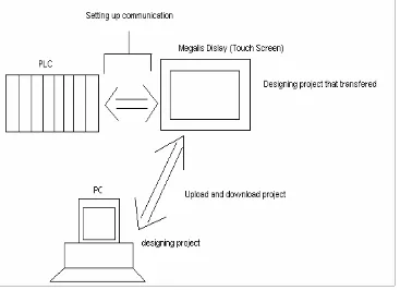
Communication of Vijeo-Designer is set up to the PLC of the target machine.
It will works together with PLC programme to implement and control the systems
that suited as required. To configure the communication setting, the types of PLC,
manufacturers, series and the cable that used are determined. Figure 2.1 shows the
communication setting between PLC and HMI.
Figure 2.2 shows the example project suing Vijeo-Designer software.Like a
citect, Vijeo-Designer environment consists of several elements. These are:
• creating variable drawing graphic,
• creating panel,
• Animating graphic,
• displaying and inputting data and
Figure 2.2: Example Project Using Vijeo-Designer
Vejio Designer is Specifically designed for configuring Magelis® XBT-G
graphic terminals, Magelis XBT-GT 3.8” graphic terminals and Magelis XBT-GT
5.7” graphic terminals, Vijeo Designer software is the ideal design tool for the
simplest control application right up to the most complex HMI installations. New
functionality in Vijeo Designer software improves load time, reduces compilation
The basic descriptions of the software are:
• An enhanced tool chest includes thousands of ready-made graphic objects
that can be dragged and dropped for faster, easier application design. Users
can also customize graphic objects to expand the graphics library. [1]
• New features, such as an alarm view with preset, configurable behavior,
expanded recipe management functions, and real-time and historical alarm
printout capabilities allow the software to be used virtually out of the box. [1]
• Open – The software operates on any PC-compatible machine running
Windows® 2000 or XP and integrates equally well in Telemecanique®
solutions and third-party architectures, connecting to Telemecanique
Modbus™, Modbus Plus™ and Modbus TCP/IP, Unitelway, Siemens,
Allen-Bradley, Omron and Mitsubishi APIs. [1]
• Licenses are available for one to 10 workstations, reducing software costs for
customers. [1]
• A new subscription service provides users with telephone support and
automatic upgrades and patches. [1]
2.2 Interface Overview
An interface is defines as the communication boundary between two entities,
such as a piece of software, a hardware device, or a user. In general it refers to an
abstraction that an entity provides of itself to the outside. This separates the methods
of external communication from internal operation, and allows it to be internally
modified without affecting the way that outside entities interact with it, as well as
provide multiple abstractions of it self. It may also provide solutions that given the
translation between entities which do not speak the same language, such as between
a human and a computer. Because interfaces are a form of indirection, some
additional overhead is incurred versus direct communication. The interface between
a human and a computer is called a user interface while interfaces between hardware
components are physical interfaces. The types of access that interfaces provide
procedures, exception specifications and method signatures. In some instances, it
may be useful to define variables as part of the interface. It often also specifies the
functionality of those procedures and methods, either by comments or by formal
logical assertions. [2]
As an example:-
The interface of a software module A is deliberately kept separate from the
implementation of that module. The latter contains the actual code of the procedures
and methods described in the interface, as well as other “private” variables,
procedures, and etc. Any other software module B (which can be referred to as a
client to A) that interacts with A is forced to do so only through the interface. One
practical advantage of this arrangement is that replacing the implementation of A by
another one that meets the same specifications of the interface should not cause B to
fail as long as its use of A complies with the specifications of the interface.
2.2.1 Use of Interface
The concept of interface is the foundation of modular programming, a
pioneer and a standard ingredient of object-oriented programming. In object-oriented
programming, an object’s interface consists of a set of methods that the object must
respond to. Note that the object does not make its instance variables a part of its
interface. These are typically proved by means of access methods. Some
object-oriented programming languages command that the interface to the object be
specified to the compiler separately from the implementation of that object, while
others relax the requirement. For example, a class in a programming language such
as Objective-C consists of its interface, specified in a header file, and the
implementation in the source file. Because of the dynamically typed nature of
Objective-C, one can send messages to any object, and the interface to the class
becomes important as it specifies the methods the class responds to. Some
programming languages support private and protected implementation of an
interface. Thus, the public methods declared in an interface can easily become
The Eiffel language includes in the interface of a class its invariants and the
pre- and post conditions of the methods of the class. This is essential to the
methodology of design by contract, and may be regarded as an extension of the
conditions imposed by the types of the arguments. These rules may be specified in
the implementation of a class or in an ancestor which may leave the methods
unimplemented. They are extracted by language processors to provide an interface
view in the development environment and to generate run-time assertions (checks) in
debug versions. The language also ensures that derived classes obey the contracts of
their ancestors.
2.2.2 User interface
The user interface (or Human Machine Interface) is the aggregate of means
by which people interact with a particular machine, device, computer program or
other complex tool. The user interface provides means of:
• Input, allowing the users to manipulate a system
• Output, allowing the system to produce the effects of the users' manipulation.
A graphical user interface (GUI) is a type of user interface which allows people
to interact with a computer and computer-controlled devices which employ graphical
icons, visual indicators or special graphical elements called "widgets", along with
text, labels or text navigation to represent the information and actions available to a
user. The actions are usually performed through direct manipulation of the graphical
elements. The term GUI is historically restricted to the scope of flat screens with
high resolution graphics capable of describing generic information, in the tradition of
the research at Palo Alto Research Center. The term does not apply to other high
resolution types of interfaces that are non-generic, such as video games, or not
restricted to flat screens, like Volumetric displays. [2]
2.2.3 Precursors to graphical user interfaces
The precursor to graphical user interfaces was invented by researchers at the
Stanford Research Institute, led by Douglas Engelbart. They developed the use of
concept of hyperlinks was further refined and extended to graphics by researchers at
Xerox PARC, who went beyond text-based hyperlinks and used a GUI as the
primary interface for the Xerox Alto computer. Most modern genera l-purpose GUIs
are derived from this system. As a result, some people call this class of interface a
icons. The PARC User Interface employs a pointing device in addition to a keyboard.
These aspects can be emphasized by using the alternative acronym WIMP, which
stands for Windows, Icons, Menus and Pointing device.
2.3 Evolution of Graphic User Interface
Following PARC the first commercially successful GUI-centric computer
operating models were those of the Apple Lisa but more successfully that of
Macintosh System graphical environment. The graphical user interfaces familiar to
most people today are Microsoft Windows, Mac OS X, and the X Window System
interfaces. IBM and Microsoft used many of Apple's ideas to develop the Common
User Access specifications that formed the basis of the user interface found in
Microsoft Windows, IBM OS/2 Presentation Manager, and the Unix Motif toolkit
and window manager. These ideas evolved to create the interface found in current
versions of the Windows operating system, as well as in Mac OS X and various
desktop environments for Unix-like systems. Thus most current graphical user