WALKING ROBOT
TAN POH TOO
“I hereby declared that I have read through this report and found that it has comply the partial fulfillment for awarding the degree of Bachelor of Electrical Engineering (control, instrumentation and automation)”
Signature : ………
Supervisor’s Name : EN FARIZ BIN ALI
DEVELOPMENT OF A WALKING ROBOT
TAN POH TOO
This Report Is Submitted In Partial Fulfillment Of Requirements For The Degree of Bachelor In Electrical Engineering (Control, Instrumentation and Automation)
Faculty of Electrical Engineering Universiti Teknikal Malaysia Melaka
“I hereby declared that this report is a result of my own work except for the excerpts that have been citedly clearly in the references..”
Signature : ………...
Name : TAN POH TOO
iii
ACKNOWLEDGEMENT
v
ABSTRAK
ABSTRACT
vii
TABLE OF CONTENTS
CHAPTER CONTENTS PAGE
PROJECT TITLE PAGE i
AUTHENTICATION ii
DEDICATION iii
ACKNOWLEDGEMENT iv
ABSTRAK v
ABSTRACT vi
TABLE OF CONTENTS vii
TABLE LIST x
FIGURE LIST xi
1 INTRODUCTION 1
1.1 Objectives of the Project 2
1.2 Scope of the Project 3
1.3 Problem Statement 4
1.4 Project Planning Schedule ( Gantt Chart ) 5
2 LITERATURE REVIEW 6
2.1 Introduction 6
2.2 Background 7
2.3 AMOS-WD02 8
2.3.1 AMOS-WD02 Specification 9
2.4 Nico 11
2.4.1 Nico’s Specification 12
2.5 Crocobot Project 14
3.1 Microcontroller 16
3.1.1 Decoder 17
3.1.2 Control Unit 17
3.1.3 Arithmetic Logic Unit 18
3.1.4 Memory 18
3.2 Why use Microcontroller? 20
3.3 Choosing suitable Microcontroller 21
3.4 Why choose PIC 16F877A 21
3.5 PIC 16F877A 22
3.5.1 Microchip PIC16F877A Features 23
3.6 Motor 26
3.6.1 DC Motor 26
3.6.2 Stepper Motor 29
3.6.3 Servos 29
3.7 Choosing suitable motor 30
3.8 Motor driver L293B 30
3.9 Body 33
3.10 Circuit 34
3.10.1 Components 35
3.11 Simulation 35
3.11.1 Simulation test coding 35
3.11.2 Simulation circuit 37
3.11.3 Simulation result 37
4 METHODOLOGY 39
4.1 Flowchart 39
4.2 Tools 40
4.3 MicroC 40
4.4 Writing coding 44
4.5 Programmer 45
4.6 Comparison of the robot’s walking algorithm 49
5 RESULT 51
ix
5.2 LED blinking circuit 53
5.2.1 LED blinking coding 53
5.3 Driver circuit 54
5.4 Robot Coding 55
5.5 Power supply 56
5.6 Motor 58
5.7 Robot structure 59
5.7.1 Material 59
5.7.2 Parts 60
5.7.2.1 Robot base 61
5.7.2.2 Robot legs 62
5.7.3 Combining 64
6 DISCUSSION & CONCLUSION 67
6.1 Problems 67
6.2 Methods & solutions 68
6.3 Future development 70
6.4 Conclusion 70
REFERENCES 71
TABLE LIST
NO TITLE PAGE
1 Table 1.1: Gantt chart 5
2 Table 3.1: Functional Use Case analysis for MCU 19
3 Table 3.2: Main feature of Microcontroller 25
4 Table 3.3: Control pin function 32
xi
FIGURE LIST
NO TITLE PAGE
1 Figure 1.1: Flow chat of Walking Robot 3
2 Figure 2.1: AMOS-WD02 8
3 Figure 2.2: Basic principle of movement of a salamander leg 8
4 Figure 2.3: Backbone joint of AMOS-WD02 9
5 Figure 2.4: Nico 11
6 Figure 2.5: Crocobot 14
7 Figure 2.6: Controller circuit board for Crocobot 15 8 Figure 2.7: Remote control schematic diagram for Crocobot 15
9 Figure 3.1: FUCM for Microcontroller System 20
10 Figure 3.2: PIC 16F877A pin diagram 22
11 Figure 3.3: Actual view of PIC 16F877A 22
12 Figure 3.4: DC Motor 26
13 Figure 3.5: Structure of DC Motor 27
14 Figure 3.6: Operation of DC Motor 27
15 Figure 3.7: Attraction of rotor to field winding 28
16 Figure 3.8: Stepper motor 29
17 Figure 3.9: Servos 29
18 Figure 3.10: Pin diagram for L293B 31
19 Figure 3.11: Connection for bi-direction DC motor 32
20 Figure 3.12: Four legged walking robot 33
21 Figure 3.13: Control circuit for walking robot 34
22 Figure 3.14: Simulation circuit 37
[image:13.595.121.516.195.763.2]28 Figure 4.1: Methodology flowchart 39
29 Figure 4.2: Tools 40
30 Figure 4.3: Open new project in MicroC 41
31 Figure 4.4: New project window 41
32 Figure 4.5: New blank page in MicroC 42
33 Figure 4.6: Message of success compiling process 42
34 Figure 4.7: Steps on writing the coding 43
35 Figure 4.8: Schematic for USB programmer 44
36 Figure 4.9: Circuit board of USB programmer 45
37 Figure 4.10: Programmer software WinPic800 46
38 Figure 4.11: Opening file to load 46
39 Figure 4.12: Selecting the hex file 47
40 Figure 4.13: Code changed after file loaded 47
41 Figure 4.14: Program the device 48
42 Figure 4.15: Programming completed 48
43 Figure 4.16: Structure of the NICO’s leg 49
44 Figure 4.17: Joint of the robot leg 50
45 Figure 5.1: Components for testing 51
46 Figure 5.2: Completed control circuit board 52
47 Figure 5.3: LED blinking schematic circuit 53
48 Figure 5.4: LED blinking circuit board 54
49 Figure 5.5: Completed driver circuit board 55
50 Figure 5.6: Coding for the walking robot 56
51 Figure 5.7: L7805 Voltage regulator schematic circuit 57 52 Figure 5.8: L7805 Voltage regulator circuit board 57
53 Figure 5.9: AA Batteries unit used 58
54 Figure 5.10: TAMIYA Twin motor gearbox 58
55 Figure 5.11: Aluminium 59
56 Figure 5.12: Walking Robot Parts 60
57 Figure 5.13: Robot base to hold the motor and the strip board 61
58 Figure 5.14: L-connector 61
59 Figure 5.15: Robot’s right leg 62
60 Figure 5.16: Robot’s left leg. 63
[image:14.595.106.514.61.774.2]xiii
62 Figure 5.18: Combined walking robot 64
63 Figure 5.19: Walking robot’s top view 64
64 Figure 5.20: Walking robot’s back view 65
65 Figure 5.21: Walking robot’s right view 65
66 Figure 5.22: Walking robot’s left view 66
67 Figure 5.23: Walking robot’s front view 66
CHAPTER 1
INTRODUCTION
A robot is a mechanical or virtual, artificial agent. It is usually an electromechanical system, which, by its appearance or movements, conveys a sense that it has intent or agency of its own [6]. Not all of the machine can be identify as robot because robot have several of properties which is either has been artificially created, can sense its environments, can manipulate or interact with things in its environment, has some degree of intelligence, or ability to make choices based on the environment, or automatic control / preprogrammed sequence, programmable, can move with one or more axes of rotation or translation, can make dexterous coordinated movements, appears to have intent or agency or is in some degree metallic.
2 products, for entertainment or to perform certain tasks like vacuum cleaning or mowing.
Walking robots are often slower than driving robots, but they have the important advantage that they navigate over terrain, while driving robots require a more or less flat surface. The more legs a walking robot have, the easier to balance. Legged robots usually require two or more motors depend on the degrees of freedom (DOF) per leg of the robot. Walking robots can be define with [7]:
• All legs must operate in a cyclical fashion.
• No wheels or rotary wheel-like appendages will be permitted for locomotion. • The ground contact point on the foot can not revolve around some origin that
is located on the leg or hip.
• The entire weight of the robot must be completely supported by the robot’s legs.
• All legs must be actively used to move the robot.
• All passive legs/appendages that are used to assist in balancing the robot, or locomotion, must separate (lift/hop/move) off the ground at some point during each walk cycle.
• If the robot falls over, external appendages/arms can be used to help the robot get back on its feet.
In this project, the walking robot will be using a PIC 16F877A microcontroller as a control system for this robot. While to control DC motor with PIC, motor driver is required to change the low current control signal to high current control signal to drive the DC motor.
1.1Objectives of the Project
The aim in this project that need to be achieved:
2. The robot able to walk forward, backward, turns left and right.
3. When the legs of the robot lift up, the remaining legs of the robot must be able to walk and hold the weight of the robot.
1.2Scope of the Project
[image:18.595.266.421.433.712.2]A program will be written with MikroC with the movement of the walking robot being programmed. A variety of motion of the robot will be design to achieve the objective of this project. The program will decide which output port of the microcontroller PIC 16F877A will be “ON” or “OFF”. The output ports of the PIC 16F877A are connected to the motor driver which use to convert the low current signal from microcontroller to high current signal, and from there, it will drive the motor rotation based on the signal from microcontroller.
Figure 1.1: Flow chat of Walking Robot Program coded
Motor driver Microcontroller
( 16F877A )
Signal send
Signal send
Robot walk as desired
4 For the hardware electronic parts, the controller board will be built using PIC 16F877A. While driver board will be built with L293B to control two dc motor using two set of H-bridge in the L293B chipset. Driver board and control board will be connected through port B and port C at PIC 16F877A and the input pins from the L293B.
While for mechanical hardware parts, aluminium will be used to construct the robot’s structure including robot base, legs, joint and others related parts.
1.3Problem Statement
1.4Project Planning Schedule ( Gantt Chart )
6
CHAPTER 2
LITERATURE REVIEW
2.1 Introduction
Ever since robots have been invented, people have been very interested in them. Robotic technology has made many things possible, including space and deep sea exploration, dangerous military and police missions, new types of entertainment, and new toys that talk and respond like real creatures. Robotic have been a subject of philosophical and a source of literary inspiration for hundreds of years. It is only since this century that robots have emerged out of fiction and turn philosophy into the real world. Today robots are common-place, for instance, fixed-location robotics arms now tirelessly perform precise repetitive tasks for industry. However, robots still have significant limitations. Specifically, most industrial robots require the parts they operate on to be precisely aligned and mobile robots that move around in an environment are still largely confined to academic research laboratories.
sometimes when operating, doctors have to use a robot instead. A human would not be able to make a hole exactly of an inch wide and long. When making medicines, robots can do the job much faster and more accurately than a human can. Also, a robot can be more delicate than a human. Some doctors and engineers are also developing prosthetic (bionic) limbs that use robotic mechanisms. Dr. David Gow, of the Prosthetics Research and Development Team at Princess Margaret Rose Orthopaedic Hospital, made the first bionic arm called the Edinburgh Modular Arm System (EMAS) in 1998 [1]. For military and police, Police need certain types of robots for bomb-disposal and for bringing video cameras and microphones into dangerous areas, where a human policeman might get hurt or killed. The military also uses robots for locating and destroying mines on land and in water, entering enemy bases to gather information, and spying on enemy troops. Robots nowadays are being invented for the purpose of entertainment and as a toy too.
2.2 Background
8 2.3 AMOS-WD02
Figure 2.1: AMOS-WD02
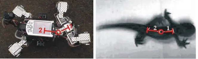
AMOS-WD02 (Advanced MObility Sensor-driven Walking Device) is a simple platform for experiments with neural perception - action systems which were built referred to morphology of salamanders. This walking machine has 4 legs, each with 2 degrees of freedom, and one back joint. With IR-sensors and auditory sensors, it had different reactive behavior; such as obstacle avoidance and sound tropism [2].
[image:23.595.181.497.585.708.2]AMOS-WD02 has three parts which is legs, body and sensors. For the leg parts, each leg has two joints (two degrees of freedom (DOF)) which are a minimum requirement to obtain the locomotion of a walking machine and which follow the basic principle of movement of a salamander leg. The upper joint of the legs, called thoracic joint, can move the leg forward and backward and the lower one, called basal joint, can move it up and down. While for body, it’s inspired by vertebrate morphology of the salamander’s trunk and its motion, the robot was constructed with a backbone joint which can rotate around a vertical axis. It facilitates a more flexible and faster motion [2].
Figure 2.3: Backbone joint of AMOS-WD02
The backbone joint is also used to connect the trunk where two hind legs are attached with the head where two forelegs are installed. The AMOS-WD02 has two IR sensors (called antenna-like sensors), two auditory sensors and one wireless camera [2].
2.3.1 AMOS-WD02 Specification
Below is the specification for AMOS-WD02 [2]:
1. Mechanics


![Figure 2.2: Basic principle of movement of a salamander leg [2]](https://thumb-ap.123doks.com/thumbv2/123dok/667042.81964/23.595.227.412.108.368/figure-basic-principle-movement-salamander-leg.webp)