SPEED PERFORMANCE OF SPACE VECTOR PULSE WIDTH
MODULATION DIRECT TORQUE CONTROL FOR FIVE LEG INVERTER
SERVED DUAL THREE-PHASE INDUCTION MOTOR
N.M YAAKOP
PROFESOR MADYA DR ZULKIFILIE BIN IBRAHIM
MD HAIRUL NIZAM BIN TALIB
UNIVERSITI TEKNIKAL MALAYSIA MELAKA
Speed Performance of Space Vector Pulse Width
Modulation Direct Torque Control for Five Leg
Inverter Served Dual Three-phase Induction Motor.
N.M. Yaakop, Z. Ibrahim, IEEE member and M.H.N. Talib, IEEE member
Abstract-Independent control of multi-machine with single-converter systems is the motivation of this research study. As in the previous literature review, there is no report regarding speed control applying space vector pulse width modulation direct torque control (SVPWM-DTC) method for dual three-phase induction motor (IM) fed by a five leg inverter (FLI). Therefore, in this paper, a new and simple control method based on SVPWM-DTC for dual three-phase induction motors with only one drive of five-leg voltage source inverter is investigated. The method effectively allows independent control of two three-phase IMs. Simulations of different speed commands and variation of load condition tests have been performed. Future work is to do comparative study between vector controls (VC) versus OTC methods to the FLI performance.
Keywords-compo11e11t; dual motor, two three-phase motors, five-leg inverter, space vector pulse width 111od11/atio11 direct torque
co11tro/.
!. INTRODUCTION
Presently, to drive two three-phase !Ms with single drive independently has attracted major interest among the researchers and industries because of cost reduction, saving space and reduction of inverter losses. It is believed to be a potentially interesting solution for two-motor constant power applications, for example, centre-driven winders (I]. Although a large number of studies have been made on VC method applying to the FLI (1-3], none is known about employing DTC to FLI.
It is now recognized that the two high-performance control strategies for IM are FOC and DTC [4-6]. These methods have been invented in the 70's and 80's. They have different operational strategies but with the same target that is to control effectively the motor torque and flux. Both control methods have successfully implemented in industrial products [7]. DTC [8-9] has been gaining more popularity since it is invented due to its exceptional dynamic response and less dependence on machine parameters. It also has been applied to the multi-phase motor [10-11] applications.
FU had been introduced with decrease of switch count compare to standard two three-phase two-level inverter which has six legs. There are researches on FU applying SVPWM techniques in its application [12-13] and also there are researches on applying SVPWM in DTC using normal three-phase motor [14-15]. Hence, by combining both methods to a system, this paper investigated the new SVPWM-DTC to
control FL!. SY-based PWM introduced by [1, 12] is implemented herein.
II. CHARACTERISTIC OF FIVE-LEG INVERTER
A. Main Circuit Topology of Five-leg inverter
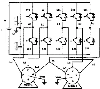
Five-leg two-motor drive structure offers a saving of two switches when compared with the standard dual three-phase voltage source inverter (VSI) [16-18]. Fig. l shows the main structure of the FLI. The FL! serves two three-phase !Ms. Both motors need three inputs, as the results the C leg works as a common leg. Leg A1 and B1 are connected to phase U and V
of motor one (Ml), while leg A2 and 82 are connected to phase
U and phase V of motor 2 (M2) respectively. Switching functions S; (i""l,2, 3,4,5) are defined as S1 = I when the upper
switch is on and S1 = 0 when it is off. There are a total of 32
switching states (25) in a five-leg VS!, available for control of
the two motors (I].
Figure 1. Main circuit topology of two three-phase lM fed by five-leg inverter.
[image:2.597.349.514.388.536.2]range and load variations that the motors can handle also reduced.
B. SVPWM-based DTC
DTC has simple structure and fast torque response advantages. DTC with space vector modulation (SVM) scheme is proposed in order to improve the classical hysteresis DTC. Reference [8] reported that compare with the steady-state performance of lookup table OTC and SVPWM-DTC, the latter produces much lower torque ripple. This is results from the injection of zero-vector instead of backward active vectors to reduce torque. Another advantage of SVPWM-DTC is it operates at a constant switching frequency.
The three-phase IM SVPWM-DTC will be discuss because in the schemes that being developed in this paper the standard three-phase modulators are used to produce the 5 gates signals to trigger the FLI (as in fig. 3). In the control structures, SVM algorithm is used. The type of SVPWM-DTC strategy depends on the applied flux and torque control algorithm. In this paper SVPWM-DTC scheme with PI controllers will be implemented as in fig.2 below (21]. Fig 2 shows the block diagram of SVPWM-DTC with PI controllers IM drive.
• 7" .
セZQMセQZQ@
セカM・jZセL@
U
Q
セ
Q@1r:l __
[l-;:.2
.
LセL@
N{G}MGMMセMーjMエjセ@
-セᄋMM
cd
Figure 2. Block diagram ofSVPWM-DTC three-phase IM drive.
Equations (I) and (2) show the principle'"" of OTC on calculating the flux and electromagnetic torque. Here
@
andfl
are voltage and current vector respectively in stationary reference frames. The stator flux linkage(<{if)
calculated as (I).qiJ=
../(fl/ -
i;eR
5)dt
(1)The electromagnetic torque
fe
can be calculated as (2).セMSpHセウ
Ie-4
Q
セウ@ セウヲウI@(/Jds qs-(flqs ds (2)
Where P is the number of poles, Rs is the stator resistance, [ohm]
n.
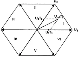
The basic principle of SVPWM algorithm is it has eight voltage vectors. There are six base vectors has same amplitude and two zero vectors (000) and (I 1 I). As shown in fig. 3, in the first sector adjacent to the two voltage vector U1 and U2 as well as the zero vector can synthesis reference vector U,0r in
accordance with the method of voltage-second balance.
(3)
Figure 3. Voltage vectors and sectors.
Where T1 and T2 are the duration time of active vectors, T0 is the duration time of zero vectors and T. is the PWM cycle. From these times switching signals
5
1,5
2 and5
3 are obtained.C. SVP WM in Fl!
There are lots of different PWM methods have been applied as the switching techniques to the FU [2, 21-25). Unfortunately by using this conventional PWM the DC bus utilization is restricted to 50% to each of the motor. As a consequence, many attempts to improve the DC bus utilization with the five-leg topology have been reported [I, 12, 26-27].
Two PWM techniques are introduced by [7, 12] for FL!, that is carrier base and SY-based PWM. SY-based technique is chosen to be implemented in OTC. The technique utilizes standard three-phase modulators to generate modulation signals for al 1 legs of a FLI. The end result enables any portion of the DC bus voltage to be allocated to any of the two motors. It produces a symmetrical switching pattern, with identical switching frequency in all the inve11er legs. The more interesting factor is that all of the 32 available inverter switching states are utilized.
Consider a SV approach to the inverter modeling. Similar principles to those explained in the case of carrier-based PWM
[I] of the FLI apply when one considers the SVPWM method for two-motor drive. The existence of zero-sequence signal injection makes it possible for the FLI being able to independently control two three-phase !Ms. It is well known that the zero-sequence signal represents a degree of freedom that is normally used to improve the DC bus utilization and reduce harmonic current losses of the carrier-based method [l]. The zero-sequence signal does not appear in either line-to-line or phase voltages of the three-phase motor. This offer a possibility to utilize the principle of zero-sequence signal injection in a very different manner for a five-leg two-motor drive.
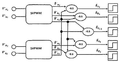
[image:3.595.366.503.59.162.2] [image:3.595.67.296.276.363.2]SV. The three-phase SVPWM modulators will generated the duty cycle values
o
over the switching period fx (time 'ON' over the total switching period) for each of the three legs. Asimple summing of the duty cycles generated can be used to determine the resulting five duty cycles for the FL!. That is,
oA,
=
Ou,+
Oc,Oc = Oc1
+ Oc
2OAz ::: Onz
+
Oc, Oez=
obz+
ii,,
(4)
The values of duty cycles calculated by each three-phase SY modulator are in the range (0: I), where the switching period Ix is equal to I p.u. Then as in normal SY zero space vector I 11 should be injected in the middle of the switching pattern, generated duty cycles will have values equal to 0.5 when the input reference is zero. After summation defined with (4), the FU duty cycles get shifted into the range (0.5: 1.5), which is not applicable with the value of the witching period. Due to this the value from the resulting duty cycles calculated using (4) must continuously subtracted by 0.5. This is shown in Fig. 3 where the principle of SVPWM for a FL! supplying a two-motor drive is illustrated [ l, I 2J.
111e net effect of the duty cycle summation is the redistribution of the application times of the zero SVs. From the first three equations of (4), it is visible tlrnt the addition of the value of the duty cycle
oc,
increases all three duty cycles, originally generated by the Ml modulator, in the same rnunner. 111us, the application time of the zero SV 111 is effectively increased, and as a consequence the application time of the zero SY 000 is decreased (before shifting by - 0.5), without affecting the application times of the two active SVs. The same explanations apply to M2 on the basis of the last three equations of(4).After the application of the SYPWM principle, these sequences and application time durations or active SVs for M 1 and M2 stay preserved in the final five duty cycles of the five-leg VS!. It can be fu11her seen that the distribution of the application times for zero vectors 000 and 111 for each of the two machines is different in FU compared with in MI and M2, whereas the total zero vector application time (sum of 000 and l 11 application times) is kept the same. It is also noticeable that there are instants within the switching period when both machines simultaneoLJsly receive their active SVs (overlapped parts, for exm11ple, vector I 1001 of the five-leg VS!, which corresponds to the active vectors I I 0 and 0 I 0 of the two machines, respectively, since inverter legs A2 and B2 supply
phases a and b of the second machine while phases c are paralleled to the inverter leg Cu). 11ms the individual SY references of each machine are complementary and the modulator is able to simultaneously satisfy the needs of both motors. It is also visible that in the remaining instants the individual SY references of each machine are conflicting and so the needs or one machine are met, whereas the second machine receives zero SY ( 111 or 000). What this means is that all 2$::::32 switching states of a five-leg VSI are utilised and there are no restrictions regarding the use of any of them. 111e resulting PWM patlern is symmetrical with two commutations per invener leg and is thus easy lo implement using standard DSP PWM units.
v·,, 0
v·.,
SVPWM
SVPWM
Figure 4. Prindplc of SVPWM for the !'LI
III. PROPOSE SVPWM-DTC IN THE FIVE-LEG ャnverteiセ@
FED Two THREE-PHASE INDUCrlON MOTOR DRIVE
Fig. 5 below shows the block diagram of the proposed SVPWM-DTC in five-leg inverter fed two three-phase motors. In the torque producing d' mid q' axis in a stationary reference frame, the torque and flux estimator equations are the same as the conventional three-phase DTC drive for each motor.
' ... セャNNNNNZヲ@
! セAイセセセGヲ@ I
..
l'igurc S. Proposed SVPWM·DTC in FLI conlrol block diagram.
IV. SIMULATION RESULTS
111e simulation investigation is performed using SVPWM-DTC to control FL!. Two identical 4 poles, 415V, 50Hz !Ms are used. 111e rated load applicable for each motor is 4Nm (half of the full single three-phase motor drives). Both the transient and steady-state performance of the drive is investigated with a series of tests. No load, with load variations, and different speed references operation are
considered. SVPWM-based DTC of section III 1s
[image:4.597.312.521.91.202.2] [image:4.597.308.534.325.445.2]Fig. 6 shows the first test where different speed rererences (I 00%=600, 50%=300 and 25%= 150 rpm) are applied for motor two (M2) while motor one (Ml) is maintain constant at 600 rpm, both are under no load condition. The figure also shows thnl the controller can well control independently both motor al different speed references. Table I shows the observation of this Lest. Transient speeds performance of the lowest speed reference gives faster respond, followed by the next speeds reference accordingly. While the steady-state performance is excellent for all difference speed command.
600
suo
100
\
Wroh:l5D0rprn for both m:>torsOセセセセ@
セセセ⦅N⦅NLNN@ wヲQAlセRZZL_PPセ@ Mセ]セセNNゥ@
\
W"'IJ.12•150'1'!"セ@ U セ@ M M U U U U
[image:5.605.60.283.160.441.2]·nmc(x)
Figure 6. Variation
or
speeds reference for M2= 600, 300 :md 150rpm while Ml=600qim. holh mot<>rs under 110 ln;1d
TABLE I. 01.\SERV ,\ llONS OF INf)i;PEND!lNT SPEEDS CoNTl!Ot UNDEll
No Lt>.\D TESTS.
No. Dcscri pt ion Sllccd (rnml Obscrv:ttiun
Ml Ml 7hm.\·fout rcspon.ve
time
I. IOUCk rated 600 600 Longest
2. sorit. rated 600 30() Shon er
3. 25tA:, n.Hcd 600 150 raste:st
Fig. 7-11 shows the simulations of with load conditions. The analysis can be seen in table 2. The first one is applying same speed and same load al the same time for both motors. Both motors archived a very stable steady-stale operation after a slight speed reduction after load disturbance. As in fig.8-9 applying same load to both motors that having different speeds, it also resulting in a very stable after load disturbance reaching the steady state operation. For fig. I 0. with same speed reference to both motors (M l=M2=600rpm) and load is applied to only M 1 (4Nm), while M2 is at no load condition, the result is the speed for MI is stable, equal to lig. 7 and no innuences to the performance of M2. The torque rated applicable for each motor in this ti ve-leg drive performance is 4Nm. so the total is 8Nm. The last load test done is to apply lo only one motor, Ml the total torque (8Nrn) that FL! able lo handle while M2 is at no load as in fig. 11. Comparing the results with fig. 7, it is obvious that the FLI can handle 8Nm but must be dividing equally to both motors,
if only one having full loaded the control system could not be well performed.
6 1 0 1 , - - - . - - - , - - - - . - - - - . . , - - - , - - - ,
605
1600· ヲヲQQBBBB]]]]セ]]BGQILLLB]」\セセ]]M]]]]]M]]]]]]]@
.... =====l
"" 595 Applying load 4Nm
セ@
"'
590585
0.5 0.6 0.7
tゥュ・サセI@ o.s 0.9
Figurf.! 7. Ml aml M2 having ウZQQQセ@ s1>ecd reference with s:1111e '""". 600
rpm. 4Nm al t=0.6,;_
05
••
01.
..
...
(a)
l--- -·- --. :----:---. --'.---1
セMMMMMMMMMMMMMMMMMMMMMMMMMMMMMMMᄋ@
l·· -- ---
MMMセN@
--•- - -
Mセ@
- . - --
---J1oe:::i - - - _, .. -- -- .. - - - セ@ ... .. . . - - ..
)'II -- - - • - - •
"---·
Ii.ii' 11• 1Ul G.6' 11-'l 11-"
(b)
u: ZッMャZエセ@ - - -
-.. ,,. - - - -MG]Mセ@ - - - -·
---
--- セMM ------
---(c)
J
セᄋェ@
l'J
'i
I'·'
'·'
0.)...
••
0.1...
.
..
(a)
M l \ - - - ·
Ul
-
---_____
...---j'6 - - -
-LLセ@
- - - -
.- - - -
--
- - --
---
- --- --- -
--
-..
..
..
(h)
Ul - - - ,.... - - ... - - - .. - - -
-.,,
- - - -
-
- - - - -
-----
-- - - -
-
----f :::
= =]M]MZMZᄋZ[M]セM]MM]M]M]M]MM]@
-=-= =--=-=-=
]セM]]@
= ==
== =
::.:=-=
,..,, -
- - - -- - - -
- - - - --
--
--- - -
--- - - - --14? - - - セ@ - - -
-M - - - -
..
,
(C)
Figure 9. Speed MI =600 rpm. M2= 150 rpm with same lo:id 4Nm at !=0.6s. (a) Whole process: (bl and (c) enlarge picture of MI :iml M2 al t:o:{}.6s.
セ@
---f
セMZMM セ@
---
セ@ セ@ セ@ セ@ セ@ セ@セ@セ@セ@ セ@ セ@ セ@ [セセL[mセ|[L[LセZセᄋiZ\セ@
---
セ@ セ@ MMMセ@
-
セ@
S9
-tt
-セ@ u m u w u
Ti111cM
Figure 10. S:ulll! speed n:fercncc MI mul M2=600 rpm, Applying load 4Nm al !=0.6s wonly MI, M2 no load.
--,----···-
ᄋセセᄋセMセN@Af'Pl)lqMl .. ll'\111.,J.U ... t.'nlOld
1-l
[image:6.595.310.534.71.151.2]Figure 11. Same speed ref.MI and M2=600 rpm. Applying to!al of two rated load possible for bo!h motor 10 only one motor M 1=8Nm :11 !=ls. M2 no load.
TABLE II. OBSERVATIONS OF INDEPENDENT SPEEDSCONTHOL UNDER
LOAl>TESTS
Nu. Description Sneed (mm) Load (N.m) Obsermliun
Ml M2 Ml M2
I. Same load and 600 600 4 4 Scable SIJl)Cd
Small speed
2. 600 300 4 4 reduction afler
S:11Th! load, load
, _ dilforcnt speed disturbance
Small speed
3. 600 150 4 4 rcduccion after
load disturbance
Same speed,
4. one loaded, 600 600 4 0 Scablc
another no
load Sa111c >peed,
One full FLI Ou! of
SICady-5. rnted load, 600 600 s 0
nnothcr no Stale
load
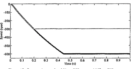
Fig. 12 shows the forward reversed operation of the two motors supplies by the FL!. Smooth operation appeared at both motors during transient and steady-state. In fig. 13 shows the reversed operation of both motors at no load but with different speed references MI al -600 rpm and M2 al -300 rpm. 111e result shows that both achieved a very stable steady-state condition.
••
••
[image:6.595.64.538.86.404.2] [image:6.595.68.292.463.577.2] [image:6.595.309.531.504.598.2]O.t 0.2 O.J 0.4 0.5 0.6 0.7 0.8 0.9
Time{!!)
Figure 13. Reversed operation MI
=
-600'l'"'
and M2=
-300 rpmV. CONCLUSION
Simulation of a SVPWM-DTC fed FU has been developed to control independently the speed of two three-phase !Ms. Simulation results investigate and proven this structure. 111e FU really enables different speeds reference command and load torque on both motors.
111 121 131 141 !SI 161 171 181 191
J 101
[Ill
REFERENCES
M. Jones, S.N Vukos:ivic, D. Dujic, E.Lcvi. P.Wright. "Fi\'c-lcg inverter
P\VM tt.::chnique for rt!dttced s\vitch count two-mo1or cnns1ant power
applications," JET E/1•ctr. Po11t•1· Af'pl .. 2008. vol.2, no. 5, pp. 275-287. M.Hizumc, S. Yokomizo. and K.Matsuse, "lmlcpcndcnt Vector Conlrol of Panillcl-Conncctccl Two Induction rvtolors by a Five- Leg Inverter",
/f)lh Eorf'JJ('lllt cュセヲHイ」Nュᄋ・@ w1 /'u\1'l'f Elt•<'lnmics mu/ Applfr·aricms.
CD-ROM. paper 778, 2003.
S. Gatmic. "/\ polyphasc Cni1esian vector :tppmach to control or polyph:L<e AC machines," Proc. IEEE !11<1. Appl. Sm·. t\111111<1/ ォヲイ\GエゥQQNセ@
/AS. Rome, lrnly, 2000. CD-ROM p<lpcr 38_02.
I. Takashi and T. Noguchi. "A new アオゥ」ォMイ」セカョョウ・@ aml high i:ffidem:y co111rol s1m1egy of an induction molnr ... IEEE '/i·flus. Intl. Applii'ar .. vol.
I A-22, Scp./Oct. 1986.
P. Tii1incn. "The next gcncm1ion nlolor con1rol mcihod, OTC direct
torque t.:ontrol," in Proc•. Im. Conf. Power Eh•ctnmics. Driw:s awl
E11eri:.1· Sy.r/<'111 for /11t!11.\"frial Grn111h. New Delhi, India, 1996, pp. 37-43.
N. イセオュコNゥN@ A.HAiim ... Di イ・」セ@ torque cnntml nf l11duc1ion machines with
constant switching frequency and 11.!dm:ed con.1uc ripple,'' IEEE Trans.
011 l11d11sfl'ial eィイエョュゥ」NセᄋN@ vnl. 51. no. 4. August 2004.
M. Mcrzoug and F. No1ccri. Bcッューセオᄋゥウッョ@ of tield-oril:nlcd t:onlrol and direct torque control for permanent magnet synchronous motor {pmsm),"
Pmceetfill8S of uru·/d ャャcG。エャヲAjjセ|G@ of sci<•nce. Engim.'eriug mul Teclr11olo1:y
4 5 2008 299 P;igc 2.
S. Lu, K. Cur-tine, 11Direc1 torque control of live-phase induction mo1or
using space vector modulation with ィセエイョュョゥ」ウ@ セャゥュゥョ。エゥッョ@ and optimal
switching: sequence.'' 2006, p. 7 pp.
G.S. Buj:i. M.P. Kazmicrkowski, "Direct torque control of l'WM invc11er-fed /\C motors - n survey," IEEE Tm11s. OJ/ lm/11stria/ Elccrm11icr. vol. 51, no. 4, l'Jl 744-757, 1\ugust 2004
H.A. Toliya1, H. Xu."/\ novel direct torque control(DTCJ mcthotl for five-phase induction tmchines," Proceedi1111s cif" 1/1e IEEE Ap1ilkd Poirer Eh·ctrcmic.< Co11fere11ce, vol. I. pp. 162-168, September 200 I.
L. Pnrs:.\ :md H.A. Toliyat, •'Five-phase permanent-magnet motor
drives," IEEE Tm11s. cm Ind. aヲGーOゥイョエゥッエQNQセ@ vol. 41. no. I. pp.30-37, Jnnu<lry/Fehru;iry 20ll5
J 121 S.N. Vukosavic. M.Jone.<. D.l)ujic, E.Levi. "An improved nictho<l for a
livt!-lcg inverli;:r supplying two lhrr!e·phase ュッエッイセBN@ l11d11stl'illi
Elcctrcmics. ISIE. IEEE lmt•n1<1fi(J11ctl Sy111f'"si11111. 2008.
I I 31 t\. H•1r:1, H. Enokijirna, K. Mntsuse. "Jndcpcndcnl Vector Cont ml of Two Induction Motors Fed by a Five-leg Inverter wi1h Space Vector Modulation," lm/11sfl)" t\pplica1i11m S11cic1y tl111111al 1'vl<'elh1g (/AS), 201 I IEEE
I 141 V.R. Nikz<lll. N.N. Ardekani, f\. Dastfan. A. Dar:ibi, "DTC-SVPWM
nlt!lhod for PMSM control オセゥョァ@ a fuzzy sta1rn· resis1ancc estimator:·
l111,•r11atlatwl Cmifc.•1't.•11C'l" m1 El<•ctronic.\· Compu/t•r Tec111wlo:.;y
//CECT), 2lll I
1151 B. Fr:incois, A. Bousc;iyrol, "Control of lwo induction motors fed hy a ti vc-phase カッャャセQァ」ᄋNウッュ」」@ inverter," 61
" !111c.1r1w1ional Cmifen.·11cc.• an
1'.-/oddi11g (lfld s;mulari<m of Eh•ctl'it: t\rf(1d1i11('S, Cotl\'('l'fl'l"S mu/ Svstems.
pp.313-318, 1999. .
1161 Y.Kirnun\, M.Hizumc. K.Oka. and K.Matsuse, "Independent Vector Con1rol of Two Induction Motors with Five-Leg l1wcr1cr by the Expanded Two Arm l'WM Mc1hod". Tire 2005 /111cmC11ic111crl Pom:r
eANNNLᄋQュQQ[HNセ@ ('rm/1•1dl("{1, pp.6lJ-(l16, 2005.
1171 K.Ok", Y.Ohama. H.Kubola. I.Miki. K.Mmsusc: "Characteristic of
lndcpcndcm Two /\C Motor Drives Fed by a Five-Leg Inverter". 2009
IEEE liulrrs11)· Appli<"aticms Sociery l111111wl Me<·ti11g, CD-ROM.
J 181 E. Levi. M. Jones, S.N. Vuk<»avic, A. lqh:tl, H.A. Toliy'11, "Modeling,
control, and experimental investigation of a five-phase ウ」ゥゥ・セM」ッョョ」」」」、@
two-motor drive wilh single invl!rler supply;· IEEE Tnms. Ind.
£icC'tm11., 2007. 54. (3), pp. 1504-1516.
!I'll 1201 1211 1221 1231 1261 1271
I'. Dclarue. A.IJouscayrt)I. ll. Fmncois."Control implcn>!ntalion or a
f1vc-lcg volt:lgr! -.sourcc·invcrh::r supplying iwo lhrec-phnsc imluclion
machines," Elc·c11"ic- Mftchi11cs 1111d Dril'<'.< Co11fi•re11<'<' IEMDC'03. IEEE /111c•111t1/i01wl pp. I 909 - 1915 vol..1. 2003. .
S.N. Pandy:i. J.K. Chatterjee, "To1t1uc ripple minimiza1ion in dil'cc1
tore.we concrol hascd JM drive. P;u-t-1: SingJc-mrc control strnrcgy."
IEEE Power Sy,,·1e111 Teduwlog.y mu/ IE££ Power India Co11f,•t't•11t·(•, 2
l'Oll'ERCON 2008.
P. Dclaruc, /l.llouscayrol, and E.Scmail."Gcncric Control Method of
mオィゥャセァ@ Yo1tagepSnurcc Converters for ヲッセエ@ Practical lmpk:mentation".
IEEE Trtm.mcliou.\· m1 pon·er elc•f.'/ronics. Vol .18, No.2. March :?:003,
PJ>.5 17-526. CD-ROM . 2003.
セhッョ・ウL@ D.Dujic, E.Levi, "/\ Pcrfonnancc Comparison of PWM
Techniques for Five-Leg VSls Supplying Two Molar Dri\'cs", IECON-2008, Tiii! 341ul A11111wl Cm1j'1•rc11n' nJ 1/11• IEEE /11clustri11/ Elccrrmrin
Sm·h't.\'. pp.50S-5 I 3. CD-ROM, 2008.
B. Fmncois, A. 13ouscayrol: 'Design nnd modeling or a live-phase
voltagc-sourcl! inverter for two induction motors'. Pr0t'. £ur. Cmrf
1'011'<'1" Eln'. and Ap11!. El'E. Lausmne. Swilzerlnnd. 1999. CD-ROM
papl!r (126.
Ph. Dcl<1ruc. A. llousc<1yrnl, E. s」ョセQゥ@ I, B. Frnncois. "Control method for
mnHikg vol(agc source ゥョカセイャ」イNセᄋ@ Proc. Eurapt'Wl foH'('r Elt•ctronics t1m/ 1\pf'/i<'C1th111.< Co11J: EPE, Gr:tz. Austria, 2001. CD-ROM l'"pcr 636. Ph. D<:larnc. /\. Ilousc<1yrol. B. Francoi,, "Conlrol implcmcntalion of;\
fi \1c-Jcg カッャャョァ」Mウッオイ」」Mゥョカセイエ」イ@ supplying two lhrcc-phasc i11duc1ion
nt'1Chines," Pm<". IEEE /111. Ef<.c. Mach. wul Dril'c'.r Collf. /£MDC.
Madison. USA, 2003, pp. 1909-1915.
K. Ob, Y. Nozaw:i, K. Malsusc, "An improved 111e!hod of volt:lge ulility factor fm· PWM control or a five-kg inverter in two induction moior drives," 1££1 Tm11s. Eh·ctr. Efrc11·f111. £11/! .• 2006, I. (I). pp. 108-111
M. Jones, 0. Dujic, E. Lc\'i, M. Behic, B. Jcl'tcnic. "A lwo motor
cenlre-、イゥカセョ@ wlrulcr ·fod hy a fivc-lt!_g voltage source inverwr," Proc.
[image:7.600.67.289.66.183.2]