WARPAGE CONTROL DUE TO HEAT TREATMENT PROCESS ON CONVENTIONAL FURNACE
MUHAMMAD ASIF BIN MD YUSOF
This report had been done in partial fulfillment for
Bachelor of Mechanical Engineering (Thermal – Fluid)
Faculty of Mechanical Engineering Universiti Teknikal Malaysia Melaka
i
I declare that I have been done reading this report and in my opinion, this report fulfill the condition in all aspect that must be in project writing as need in partial fulfillment
for Bachelor of Mechanical Engineering ( Thermal – Fluid )
Signature : ………
Supervisor Name : En. Hamzah Bin Mohd Dom
ii
“I declare that this report had been done originally from me except some of them where I have been explain each one of them with its sources”
Signature : ………
Name : Muhammad Asif Bin Md Yusof
iii
For my beloved parents:
Mr. Md Yusof Bin Jamil
Mrs. Noraishah Binti Hussin
For my supportive siblings:
Mohamad Arif Bin Md Yusof
Nurul Adila Binti Md Yusof
iv
ACKNOWLEDGEMENT
First of all, I would like to thank Allah S.W.T. because with His permission I can finish my “Final Year Project” (FYP) to complete the requirement for my graduation.
Secondly, I would like to thank to my supervisor, Mr Hamzah Mohd Dom, Lecturer of Faculty of Mechanical Engineering in UTeM, for giving me the opportunity in doing my FYP under his supervision. I also would like to thank to him for teaching me in understanding about the warpage control during the heat treatment process. He also guided me and given advised based on his experience during my progress of this project. I have learned many new things from him.
I would also like to thank to all the staff in the Faculty of Mechanical Engineering Laboratory whether they are directly or indirectly involved in this project. I would appreciate all their effort to making this project successful. I thank all of you for all your cooperation with me since the beginning of this project by giving permission to use the lab for my experiments.
I would also like to thank to all my friends especially class of 4 BMCT (G2) for being kind and helpful to me until the project is finished. The comments and advices helped me to improve the quality of this report.
v
ABSTRAK
vi
ABSTRACT
vii
TABLE OF CONTENTS
CHAPTER TITLE PAGE
DECLARATION i
ACKNOWLEDGEMENT iv
ABSTRAK v
ABSTRACT vi
CONTENTS vii
LIST OF FIGURES xi
LIST OF TABLES xii
LIST OF SYMBOLS xv
CHAPTER 1 INTRODUCTION 1
1.1 Overview 1
1.2 Objective of the project 2
1.3 Scope of Research 2
xi
2.3 Typical Furnace Components 18
2.4 Silicone Carbide Furnace 18
2.5 Conventional Standard Furnace 19
2.6 Round and Stationary Furnace 20
2.7 Stage of optimize a process or product design 25
2.8 Parameter Diagram of a Dynamic Product or 27
Process System
2.9 The Four Phase of the Methodology 29
2.10 A Quadratic Loss Function 30
2.11 Nominal-is-Better Loss Functions 32
2.12 Smaller- Is-Better Loss Functions 33
2.13 Larger-Is-Better Loss Functions 33
3.1 General Flow Chart of Project Planning 41
3.2 Experiment Flow Chart of Heat Treatment in 48
Controlling Warpage using Taguchi Method
3.3 Achieved Warped Sample From Experiment 55
xii
30 minute and Flat Arrangement in the Furnace 4.2 Experiment Result for Hardening Time Interval of 61
30 minute and Straight Arrangement in the Furnace 4.3 Experiment Result for Hardening Time Interval of 62
30 minute and Sideways Arrangement in the Furnace 4.4 Experiment Result for Hardening Time Interval of 62
xiii
4.5 Experiment Result for Hardening Time Interval of 63
60 minute and Straight Arrangement in the Furnace 4.6 Experiment Result for Hardening Time Interval of 63
60 minute and Sideways Arrangement in the Furnace 4.7 Experiment Result for Hardening Time Interval of 64
90 minute and Flat Arrangement in the Furnace 4.8 Experiment Result for Hardening Time Interval of 64
90 minute and Straight Arrangement in the Furnace 4.9 Experiment Result for Hardening Time Interval of 65
90 minute and Sideways Arrangement in the Furnace 4.10 Warped Sample Measurement Data Sheet 66
4.11 Experiment Trial and Total Defect due to Warpage 67
4.12 Calculation for S/N ratio (Larger-the-better) 68
4.13 Response Table for Signal to Noise Ratio 70
xv
LIST OF SYMBOLS
ANOVA = Analysis of Variance DOE = Design of Experiment
OA = Orthogonal Array
1
CHAPTER 1
Introduction
1.1 Overview
Heat treatment is known to be a controlled heating and cooling of metals in changing their physical and mechanical properties. This process happened without altering the product shape. Heat treatment is sometimes done due to manufacturing processes that either heating or cooling the metal such as welding or forming.
2
1.2 Objective of the project
The objective of this project are as follows:
1) To conduct an experiment and analyze warpage problem due to heat treatment on conventional furnace using Taguchi Method.
2) To optimize the heat treatment parameter on controlling warpage by conventional furnace.
1.3 Scopes of the project
The scopes of this project are as follows:
1) To do a survey on warpage problems due to heat treatment process.
2) To conduct an experiment on studying heat treatment parameter of racking arrangement at controlling warpage by conventional furnace.
3
1.4 Problem statements of the project
4
CHAPTER II
LITERATURE REVIEW
This chapter will explain about the literature review that have been done to guide the research in the future. It will explain all about Warpage, Heat Treatment, Design of Experiment (DOE) and Taguchi Method in detail.
2.1. Distortion
5
hardening process that takes place as a result of volume change during phase transformation.
Distortion can be classified into two categories that is size distortion that is the changes in volume and shape distortion that is warpage which is due to changes in geometrical form of the steel component.
2.1.1 Size Distortion
Sinha (2003) states that size distortion is the net change in specific volume between the parent and transformation product produced by phase transformation without a change in geometrical form. Size distortion occurs due to the expansion or contraction in steel component. This type of distortion is less problematic than size distortion
2.1.2 Warpage (Shape Distortion)
6
For designers and heat treaters, this type of distortion poses greater problem than size distortion. Upon heat treatment, part movement could occur immediately and sometimes later in a subsequent processing operation. Parts that is machined, cast or formed to achieve the accurate dimensions due to heat treatment, often came out from the heat treatment process with apparent changes in their dimensional structure. There are a lot of cases which the distortion that occurs is shown by warpage such as bowing or twisting of sheet metal, canning of machined pocket areas, and other forms of part movement.
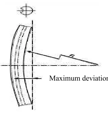
Figure 2.1 : Warpage of Thin Plate Specimen (Sources :Rajan et all. (2011))
2.1.2.1 Causes of Warpage
Based from the latest research (Croucher 2008), warpage of heated parts during and after the heat treating process is due to many factors. Some parts will warp for reasons the heat treater can control, but others will distort for causes that occurred before the heat treater received the parts and are beyond control. Thus, by understanding and
7
controlling these factors, this allows the heat treater to minimize the occurrence of heat treating warpage. The factors are:
a. Relief of pre-heat treat residual stresses
b. Expansion and contraction of parts during processing of heat treatment
c. Inadequate racking procedures in the furnace
d. The process of quenching is too fast
e. Improper quenchant selection
f. Uneven quenching due to inadequate agitation or spacing
g. Improper quench immersion rates
h. Furnace air flow design in relation to part orientation
2.1.2.2 Minimizing Warpage
8
a. Stress Relieving
The presence of residual stress due to the previous machining or forging operation will enhance the tendency of warpage. Thus, fabrication stresses caused by these operations must be relieved by subcritical annealing or normalizing operation.
b. Heating Rate
The components heating rate must not be too fast or the components may crack or warp as sections are having different heat up at different rates. So, the difference in temperature can be controlled by preheating the components to a temperature below the lower transformation of steel.
c. Preheating
Preheating can reduce shape distortion in steels by reducing the thermal stresses that is made. This is due to the gradient temperature prevailing between the surface and interior part of component. Then, for large cross-section, complicated parts and high alloy steels that has poor thermal conductivity, it is preferable to carry out two-stage preheating.
d. Quenching Media
9
e. Press Quenching
Press quenching or die quenching of steel is not common to most of commercial heat treating industries. So, during press quenching, warpage can be minimized by physical restraint of part during its rapid cooling from austenitic condition. So, quenching jigs are used for this purpose.
The part is clamped in a jig and then placed in a hydraulically operated press after heating. Then, the jig should be preheated in avoiding rapid cooling of the surface of component which comes in contact with the jigs. Along with the closing of the press, oil is flown over the component. This will resulted in maintaining the plane shape during the quenching operation.
f. Trays, Fixtures and Supports.