UNIVERSITI TEKNIKAL MALAYSIA MELAKA
Control of X-Y Table Using Siemens PLC
Thesis submitted in accordance with the requirements of Universiti Teknikal Malaysia Melaka for the Bachelor of Manufacturing Engineering (Robotic &
Automation)
By
Suria Azlin binti Ismail
JUDUL: CONTROL OF X-Y TABLE USING SIEMENS PLC
SESI PENGAJIAN: 2/ 2006-2007
Saya SURIA AZLIN BINTI ISMAIL
mengaku membenarkan t esis (PSM/ Sarj ana/ Dokt or Falsaf ah) ini disimpan di Perpust akaan Universit i Teknikal Malaysia melaka (UTeM) dengan syarat -syarat kegunaan sepert i berikut :
1. Tesis adalah hak milik Kolej Universit i Teknikal Kebangsaan Malaysia. 2. Perpust akaan Kolej Universit i Teknikal Kebangsaan Malaysia dibenarkan
membuat salinan unt uk t uj uan pengaj ian sahaj a.
3. Perpust akaan dibenarkan membuat salinan t esis ini sebagai bahan pert ukaran ant ara inst it usi pengaj ian t inggi.
(Mengandungi maklumat yang berdarj ah keselamat an at au kepent ingan Malaysia yang t ermakt ub di dalam AKTA RAHSIA RASMI 1972)
(Mengandungi maklumat TERHAD yang t elah dit ent ukan oleh organisasi/ badan di mana penyelidikan dij alankan)
Disahkan oleh:
(TANDATANGAN PENYELIA)
Cop Rasmi:
Tarikh: _______________________
* Tesis dimaksudkan sebagai t esis bagi Ij azah Dokt or Falsaf ah dan Sarj ana secara penyel idikan, at au UNIVERSITI TEKNIKAL MALAYSIA
MELAKA
Karung Berkunci 1200, Ayer Keroh, 75450 Melaka
DECLARATION
I hereby, declared this thesis entitled “Control of X-Y Table Using Siemens PLC” is the results of my own research except as cited in references.
Signature : ………
Author’s Name : Suria Azlin binti Ismail
APPROVAL
This thesis submitted to the senate of UTeM and has been accepted as partial fulfillment of the requirements for the degree of Bachelor of Manufacturing Engineering (Robotic
& Automation). The member of the supervisory committee are as follow:
……… Main supervisor,
ABSTRACT
ABSTRAK
Kebiasaannya, aktiviti perindustrian menggunakan kawalan logik program atau programmable logic control (PLC) bagi kaedah pengawalan sistem berautomasi seperti sistem pemprosesan dan pembuatan. Perihal permulaan sistem logik merupakan ciptaan daripada versi pengganti sistem kawalan pengkomputeran bagi tujuan pengawalan mesin. Terdapat pelbagai model kawalan logik program digunakan. Tangga turutan logik atau Ladder logic merupakan kaedah aturan program bagi membenarkan
rangkaian tindakan logik dalam pembinaan struktur program, perhubungan dalaman, dan pemasaan. Dalam melaksanakan latihan ilmiah ini, Kawalan logic program SIMATIC
S7 digunakan sebagai medium kawalan perlaksaan peralatan latihan pembelajaran XY
DEDICATION
ACKNOWLEDGEMENTS
First and foremost I would like to express my sincere gratitude and appreciation to my supervisor, En. Azrul Azwan b. Abdul Rahman who provided me a lot of ideas on how to do and success in this final year project. As a principle lecturer at Universiti Teknikal Malaysia Melaka (UTeM), he has relentlessly showed his supports and intelligence in helping me to solve my problems during this project is under construction.
Then, not forgetting Pn. Aidawatty who had enthusiastic support of the report revision. With her help and guidance I’m able to gain better understanding about the project structure.
I would like to express the profound gratitude to my beloved family for incessant love and support in undergoing graduate study. They have contributed a lot by their continuous encouragement and understanding that made this research work possible.
TABLE OF CONTENTS
2.1.2.1 Motion Mechanisms...………...……….18
2.1.2.2 Loop Systems……….…………21
2.1.3.1 The Cartesian Coordinate System………….………..……...………25
2.1.3.2 Positive and Negative Movement………...………27
2.1.3.3 Positioning Program………..………...……..………28
2.1.4 Controller……….…..………..………….….….30
2.2 Programmable Logic Controller (PLC)………..………...………..31
2.2.1 Hardware………..………..……32
2.2.1.1 Mechanical Design of PLC System………..………..34
2.2.2 Internal Architecture……….………..36
2.2.2.1 The Central Processor Unit (CPU)……….………38
2.2.2.2 The Buses………..……….……….. .38
2.2.2.3 Memory……….……….………39
2.2.2.4 Input Output (I/O)Units……….……..………. 41
2.2.3 Siemens PLC……….……….43
2.2.4 Programming………..….……….. 44
2.2.4.1 Program Contact Symbols……….……….45
2.2.4.2 PLC Ladder Programming……….……….47
2.2.4.3 Functional Block Diagram………..54
4. RESULT……….………...…….……….…...63
5. ANALYSIS & DISCUSSION……….102
5.1 Analysis………...……….102
5.2 Programs Task Discussion………....………114
5.2.1 Program One Description………..…….………….115
5.2.1.1 Problem and Solution………..116
5.2.2 Program Two Description………..………….118
5.2.2.1 Problem and Solution……….……… 118
6. CONCLUSIONS AND RECOMMENDATION……….…..…………120
6.1 Observation Weaknesses and Strengths………..………...………..120
6.2 Propositions Improvement………...……….…….…..121
6.3 Recommendation and Suggestion………..……….……….122
6.4 Project Conclusion………...………..……….….122
APPENDICES……….……….126
A: Symbol, Address and Comment………126
B: Functional Block Diagram (Program One)……….………129
LIST OF FIGURES
1.1 The Various Type of XY Table 2
1.2 Project Flow Chart 6
2.1 The Experimental Setup (Yih, T.T. et al. 2002) 11 2.2 Positioning System of a CNC Machining Centre Table 11
2.3 XY Table Mechanical Components 14
2.4 Relay Diagram 15
2.5 Point-to- Point Angle and Arc (Seames, W.S. 2002) 20 2.6 Continuous-Path Angle and Arc (Seames, W.S. 2002) 20 2.7 Open Loop System Configuration 22
2.8 Open Loop System Diagram 22
2.9 Open Loop System Configuration 24
2.10 Close Loop System Diagram 24
2.11 Cartesian Coordinates System (Seames, W.S. 2002) 26 2.12 Cartesian Coordinates Quadrants (Seames, W.S. 2002) 26 2.13 Cartesian Coordinates System Point (Seames, W.S. 2002) 27
2.14 Absolute Positioning 29
2.15 Incremental Positioning 29
2.16 A Programmable Controller 33
2.17 The PLC System 33
2.18 Signals 34
2.19 Mechanical Design PLC System 36
2.20 Architecture of a PLC 37
2.21 Opotoisolator 42
2.22 Level 43
2.23 Scanning the Ladder Program 48
2.25 Logic Gates (AND, OR and NOT/XOR) 51
2.26 Function Block Diagram 55
2.27 XOR Gate 55
2.28 Logic Diagram 56
2.29 Ladder Diagram for Figure 2.28 56
2.30 Ladder Diagram and Equivalent Functional Block Diagram 57 2.31 Ladder Diagram and Equivalent Functional Block Diagram 57 2.32 Ladder Diagram and Equivalent Functional Block Diagram 57
3.1 RAD Compresses Traditional Development Activity (Dennis, A. 2003) 58
3.2 Methodology Flow Chart 61
3.3 XY Table Education Training Kit 62
4.1 Network 1, Start 67
4.2 Network 2, Stop 68
4.3 Network 3, Automatic Operation 68
4.4 Network 4, Home Position Automatic 70
4.12 Network 12, Forward Movement – Manual/Automatic 77
4.13 Network 13, Back Memory 77
4.14 Network 14, Back Movement – Manual/Automatic 78
4.15 Network 15, Up Memory 79
4.16 Network 16, Up Movement – Manual/Automatic 80
4.18 Network 18, Down Movement – Manual/Automatic 82
4.19 Network 1, Start 83
4.20 Network 2, Stop 84
4.21 Network 3, Right Movement 85
4.22 Network 4, Left Movement 86
4.23 Network 5, Forward Movement 87
4.24 Network 6, Back Movement 88
4.25 Network 7, Down Movement 89
4.26 Network 8, Up Movement 90
4.27 Network 9, Right Counter 91
4.28 Network 10, Right Comparator 91
4.29 Network 11, Left Counter 92
4.30 Network 12, Left Comparator 93
4.31 Network 13, Forward Counter 93
4.32 Network 14, Forward Comparator 94
4.33 Network 15, Back Counter 95
4.34 Network 16, Back Comparator 95
5.4 Latching Structure 112
LIST OF TABLES
1.1 Project Planning for PSM Ι 5
1.2 Project Planning for PSM ΙΙ 5
2.1 Contact Symbols 46
2.2 Basic Symbol 49
2.3 Notation 50
5.1 Button and Switch Addresses 104
5.2 Counter Pulse 109
LIST OF ABBREVIATIONS, SYMBOLS, SPECIALIZED
EPROM - Erasable and Programmable Read-Only-Memory FBD - Function Block Diagram
FC - Function
MW - Memory Word. NC - Normally Closed NC - Numerical Control NO - Normally Open OB - Organization Block PC - Personal Computer
PID - Proportional Integral Derivative PL1 - Pilot Light
PLC - Programmable Logic Control PTP - Point to Point System
Q - Output,
RAD - Rapid Application Development RAM - Random Access Memory
RIE - Rotary Incremental Encoder ROM - Read Only Memory
S1 - Switch
S7 - SIMATIS Step 7
SFC - Sequential Function Chart ST - Statement List
CHAPTER 1
INTRODUCTION
There are various types of XY table being used in machine technology. The apparatus is applied in positioning element mechanism of lathe, milling and other machine. The most was applied in control numerical controller (CNC) machining center. The XY table is use for moves to work of marking, cutting, drilling and others. The named of XY table is because of the prime activity X and Y axis. Then, there is also Z axis which is for the vertical axis.
The XY table that used on the project is a just an education training kit and located to the manufacturing engineering laboratory. There is no any automated controller have been explore on it. This (manually operate) makes more weakness in controlling performance of positioning. The suitable controller with familiar and popular in the productivity industry, PLC is used as a medium improvement the system.
The program being developing to controlling the movement XY table with functioning the buttoning with consider the bulbs and the safety regulation, then positioning the axis to the point that make with functioning the magnet to pick and place an object.
the brain module PLC called central processing unit (CPU) which is analyzing the program setup.
A PLC is a computer, having connection to external input and output. The program of a PLC has the task to set the output, depending on the input and the program. PLC diagram is performing by Boolean logic gates which are work on the equal logic equation.
The sequences of PLC working is an input accepts a variety of digital or analog signals from various field devices and converts them into a logic signal that can be used by the CPU. While the CPU responsible to make the decisions and executes control instructions based on program instructions in memory. Output modules convert control instructions from the CPU into a digital or analog signal that can be used to control various field devices for example actuators.
A program device is used to input the desired instructions. These instructions will determine what the PLC will do for a specific input. The conventional relay/ contractor control system perform all controlling processes at the same time. The program sequence is executed step by step and is repeated cyclically.
1.1 Problem Statements
The trend toward automation of production equipment is putting great demands on people since the early of 1970s. The manufacturers have worked to increase productivity, capability, reliability, and flexibility by using technologies. In order to achieve these are making use more and more automation in manufacturing. PLC is one of the solutions.
The positioning element mechanism numerically controlled XY table using manually is quietly popularly. Toward the project, although in just an education training kit its will applies controller system as same as a truly machine. These of developing program considering to the precaution rule as same in the machine production operation.
1.2 Objectives
By according to the title, the objectives of this project are:
• To recommend new program system to control the positioning axis and functioning button of XY table.
• To develop new program to control the positioning axis and functioning button of XY table.
1.3 Scope of Project
scope is consists in three main parts of XY table, PLC and Siemens S7. Below shown the element scope:
XY Table
• Learn the basic operation.
• Investigate the structure of input and output (switches button and components) and their address.
PLC and Siemens PLC
• Analyze the features and identify the components on PLC program.
• Investigate and describe the function of each device such as the counter and relay.
• Study ladder diagram and function block diagram program structure and learn how to program then minimize the program language to be a simple network program.
• Investigate the address uses and develop new program regarding to both mode control.
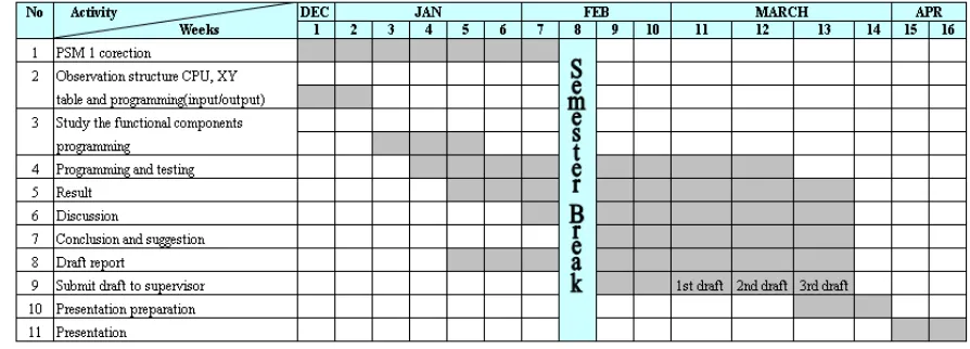
1.4 Project Planning
Project planning or methodology is the one thing should give consideration to ensure the project have been done in well condition. There are including the planning on the first and second stage of project.
Table 1.1: Project Planning for PSM Ι
Table 1.2: Project Planning for PSM ΙΙ