Comparison of Fuzzy Control Rules using MATLAB Toolbox and Simulink for DC
Induction Motor-Speed Control
Mohd Shahrieel Mohd Aras
Department of MechatronicsFaculty of Electrical Engineering UTeM Malacca, Malaysia
e-mail: [email protected]
Syed Najib Bin Syed Salim
Department of Control & Automation Faculty of Electrical Engineering UTeM Malacca, Malaysiae-mail: [email protected]
Eric Chee Sai Hoo
Faculty of Electrical Engineering UTeM Malacca, Malaysia
e-mail: [email protected]
Intan Azmira binti Wan Abd Razak
Department of PowerFaculty of Electrical Engineering UTeM Malacca, Malaysia
e-mail: [email protected]
Mohd Hendra bin Hairi
Department of PowerFaculty of Electrical Engineering UTeM Malacca, Malaysia
e-mail: [email protected]
Abstract— This paper presents a fuzzy logic control for a speed control of DC induction motor. The simulation developed by using Fuzzy MATLAB Toolbox and SIMULINK. The fuzzy logic controller is also introduced to the system for keeping the motor speed to be constant when the load varies. Because of the low maintenance and robustness induction motors have many applications in the industries. The speed control of induction motor is more important to achieve maximum torque and efficiency. The result of the 3x3 matrix fuzzy control rules and 5x5 matrix fuzzy control rules of the theta and speed will do comparison in this paper. Observation the effects of the fuzzy control rules on the performance of the DC- induction motor-speed control.
Keywords- DC induction motor, fuzzy logic control, speed control
I. INTRODUCTION
An induction motor (IM) is a type of asynchronous AC motor where power is supplied to the rotating device by means of electromagnetic induction. In a DC motor this power is supplied to the armature directly from a DC source, while in an induction motor this power is induced in the rotating device. Motors that operate from DC power sources have many applications where speed control is desirable. The most desirable characteristic of DC motors is their speed-control capability. By varying the applied voltage with a rheostat (variable resistor), speed can be varied from
zero to the maximum rpm of the motor. The increments of rpm depend of the steps of the rheostat.
Fuzzy logic controller is also introduced to the system for keeping the motor speed to be constant when the load varies. Because of the low maintenance and robustness induction motors have many applications in the industries.
The fuzzy logic is a technique to embody human-like thinking into a control system. A fuzzy controller can be designed to emulate human deductive thinking, that is, the process people use to infer conclusions from what they know. Fuzzy control has been primarily applied to the control of processes through fuzzy linguistic descriptions.
Fuzzy logic is widely used in machine control. Fuzzy logic has the advantage that the solution to the problem can be cast in terms that human operators can understand, so that their experience can be used in the design of the controller. The basic concept of the fuzzy matrix theory is that mathematical matrices can be applied to social and natural situation to predict likely outcomes. This theory use uses algorithms and algebra to analyze data.
II. THEORY
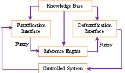
The simulation developed by using Fuzzy MATLAB Toolbox for SIMULINK and fuzzy logic. MATLAB Fuzzy logic Tollbox is use to design fuzzy logic controller. Basically, the Fuzzy Logic controller consists of four basic components: fuzzification, a knowledge base, inference engine, and a defuzzification interface. Each component affects the effectiveness of the fuzzy controller and the behavior of the controlled system. In the fuzzification interface, a measurement of inputs and a transformation, which converts input data into suitable linguistic variables, are performed which mimic human decision making. The results obtained by fuzzy logic depend on fuzzy inference rules and fuzzy implication operators. The knowledge base provides necessary information for linguistic control rules and the information for fuzzification and defuzzification. In the defuzzification interface, an actual control action is obtained from the results of fuzzy inference engine. The general structure of Fuzzy Logic Controller is represented in Figure 1.
Figure 1: Basic Configuration of Fuzzy Logic Controller
III. DESIGN
Figure 2 shows the flow chart of the methodology for this project for fuzzy logic controller part. In this project, comparison the result of 3x3 matrix control rules and 5x5 matrix control rules will be done. The number of rules is increasing to observe the effect of the different fuzzy control rules on the performances. Fuzzification is the first stage of the fuzzy logic controller process. This process converts controller inputs into information that the inference mechanism can easily use to active and apply rules. At this stage, the crisp inputs values are converted to the fuzzy inputs values. In this controller, two input variables have been defined which are speed and theta error as shown in Figure 3 and Figure 4. Meanwhile the output of this fuzzy logic controller is a voltage as shown in Figure 5. This fuzzy logic controller design for 3x3 fuzzy control rules.
Figure 2: Flowchart of the Methodology
Figure 3: Input variable “theta error”
Figure 4: Input variable “speed”
Figure 5: output variable “voltage”
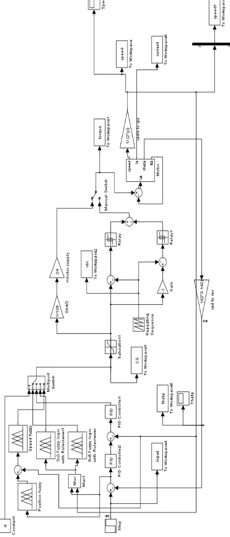
Figure 6: DC induction motor system with using fuzzy logic controller and Proportional Integral Derivative
(PID)
IV. RESULT
Figure 7 show the architecture of this DC induction motor system. Motor and encoder are coupled together. Mechanical structure which is the pendulum pole is mounted directly to the motor shaft. Interface is consisted of electronic circuit in which will responsible to pass data between pc, encoder and motor driver. Data will be received at pc side and it will be process to determine what kind of response the actuator should be exhibited.
Figure 7: Architecture of DC induction motor system
Figure 8: Closed-loop system of DC induction motor
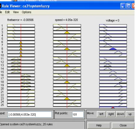
To get the result from 3x3 matrix fuzzy logic controller and 5x5 matrix fuzzy logic controllers, we set the constant 1 and 3 from multiport switch. The Figure 9 is shown as 3x3 matrix fuzzy logic control rule.
Figure 9: The 3x3 matrix fuzzy logic control rule
The input theta for the 3x3 matrix controller is 0.00417. The speed input is 4.05e-300 and the total plot point is 101. At the fifth rules, the system reaches maximum defuzzification. The Figure 10 and 11 is respectively representing the 3x3 matrix fuzzy logic control rule’s theta and speed result.
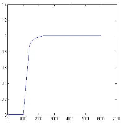
Figure 10: The 3x3 matrix fuzzy logic control rule’s theta
The Figure 11 shows the theta reaches constant stage within 2 seconds, approximately 1.7 seconds. The Figure 11
shows the speed of the system with using 3x3 matrix fuzzy logic controller.
Figure 11: the 3x3 matrix fuzzy logic control rule’s speed
The 5x5 matrix fuzzy logic controller rule is shown in Figure 12.
Figure 12: the 5x5 matrix fuzzy logic control rule
Figure 13: The 5x5 matrix fuzzy logic control rule’ theta
The Figure 13 shows the theta reaches constant stage approximately 1.5 seconds, which is earlier 0.2 seconds than 3x3 matrix fuzzy logic controller rule. The Figure 14 shows the speed of the system with using 5x5 matrix fuzzy logic controller.
Figure 14: the 5x5 matrix fuzzy logic control rule’s speed
From the graphs above, all the important data can simplify into a table. The Table 1 is shows the comparison between 3x3 fuzzy logic controller rule and 5x5 fuzzy logic controller rules. This show the 5x5 fuzzy controls have a faster response compared to 3x3. Both also do not produce
steady state so rise time alone decides that 5x5 is the superior fuzzy control.
TABLE 1: THE COMPARISON BETWEEN 3X3 FUZZY LOGIC CONTROLLER RULE AND 5X5 FUZZY LOGIC
CONTROLLER RULES
Tp Ts SSE OS% Tr
3x3 - 1.9 s 0 - 0.5 s
5x5 - 1.6 s 0 - 0.3 s
V.CONCLUSION
From the result that we occur, we would like to conclude that the 5x5 matrix fuzzy logic controller rule will offer better result than 3x3 matrix result. The number of rules in increasing, the result is better and accurate and the system being fastest to achieved a steady state, besides that, we know how to observe the effect of the different fuzzy control rules on the performance of the DC induction motor system. The theta value can reaches constant stage in a shorter time and reach the higher maximum speed.
VI. ACKNOWLEDGEMENT
We wish to express our gratitude to honorable University (Universiti Teknikal Malaysia Melaka- UTeM) especially to Faculty of Electrical Engineering for give the financial as well as moral support for complete this project successfully.
VI. REFERENCES
[1] J. Martínez García, J.A. Domínguez, Comparison between Fuzzy logic and PI controls in a Speed scalar control of an induction machine.
[2] Kandasamy, W.B. Vasantha; Smarandanche, Florentin And Ilantheral, K (2007), Elementary Fuzzy Matrix Theory and Fuzzy Models for Social Scientists.
[3] V. Chitra, and R.S. Prabhakar (2006), Induction Motor Speed Control using Fuzzy Logic Controller.
[4] L. A. Zadeh, “Outline of a new approach of the analysis of complex system and decision processes,” IEEE Trans. Syst., Man, Cybern.,
vol.SMCJ, no. 1, pp. 28-44, 1963.
[5] Mamdani, E. H. and Assilian, S., “An Experiment in linguistic Synthesis with a Fuzzy Controller, ” International Journal of
Man-Machine studies 7,pp. 1-13, 1975
[6] T. J. ROSS, Fuzzy Logic with Engineering Applications, McGraw-Hill Inc., 1991.
[7] G. Meehan and M. Joy ., “Animated Fuzzy Logic,” Coventry.,Cambridge Universuty Press.,1993.
[8] C. W. Ji, et al, “Fuzzy Logic Controller for An Inverted Pendulum