2010 International Conference on Computer Applications and Industrial Electronics (ICCAIE 2010), December 5- 7, 201 0, Kuala Lumpur, Malaysia
Simulation on Simulink AC4 Model (200hp DTC
Induction Motor Drive) using Fuzzy Logic
Controller
Nur Hakimah Ab Aziz Faculty of Electrical Engineering Universiti Teknikal Malaysia Melaka
Melaka, Malaysia hakimah@ utem.edu.my
Abstract- Classical direct torque control (DTC) has advantage in absence of coordinate transform and voltage modulator block. However, it may have disadvantage in controlling electromagnetic torque. DTC produces high ripple in electromagnetic torque as it is not directly controlled. High torque ripple causes vibrations to the motor which may lead to component lose, bearing failure or resonance. Thus, Fuzzy Logic controller is applied to reduce electromagnetic torque ripple. This paper presents the simulation analysis of Fuzzy Logic Direct Torque Controller (FLDTC) of induction machine drives. However, only the design of the controller using built in DTC induction motor drive model of Simulink AC4 will be discussed in this paper. Using FLDTC, the resulting electromagnetic torque from produced less ripple than classical DTC.
Keywords - Direct torque control (DTC); Fuzzy Logic controller (FLC); Fuzzy Logic direct torque controller (FLDTC); induction motor; Simulink
I. INTRODUCTION
More than a decade ago, direct torque control (DTC) for induction machines was introduced to give a fast and good dynamic torque response and can be considered as an alternative to the field oriented control (FOC) technique [ 1,2]. The DTC scheme is very simple in basic configuration that consists of controller, torque and flux calculator and voltage source inverter (VSI). The configuration is much simpler than the FOC system due to the absence of frame transformer. It also does not need pulse width modulator and position encoder, which introduce delays and requires mechanical transducers respectively.
Since DTC was introduced in 1986 [ l ], a large number of technical papers appear in the literature mainly to improve the performance. One of the methods is to use Fuzzy Logic controller (FLC). This controller can improve the performance of ripple in electromagnetic torque in classical DTC.
Fuzzy Logic does the resistance compensation in direct torque control at low speed region. Moreover, Fuzzy Logic provides more accuracy than classical DTC. However, it needs many rules to be followed in order to provide accuracy. Also, it requires high computational time.
Azhan Ab Rahman Faculty of Electrical Engineering Universiti Teknikal Malaysia Melaka
Melaka, Malaysia azhanrahman@ utem.edu.my
MATLAB Simulink already has a DTC induction drive model that implements the classical DTC introduced in [l]. Since this paper is using the AC4 Simulink model, only the development of Fuzzy Logic Controller will be discussed.
II. CLASSICAL DTC INDUCTION MOTOR DRIVE
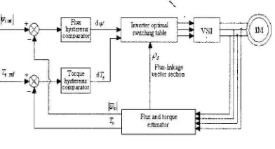
Classical Direct Torque Control (DTC) drives [1]-[6], as shown in Fig. I consists of a pair of hysteresis comparator, stator flux and torque estimator, inverter optimal switching table and a voltage source inverter (VSI). In conventional DTC, the stator flux and electromagnetic torque are controlled directly by applying the most appropriate switching state at the VSI. This appropriate switching state are determined by optimum three-dimensional switching table which has an input of the output signal of flux and torque hysteresis comparator and also the position of the flux linkage space vector. By selecting the appropriate VSI switching, the optimum voltage vector can be produced such that the machine's stator flux and torque are regulated in their respective hysteresis band. Flux and torque estimator has been used to estimate their actual value before being compared and fed into hysteresis comparator.
A. Three Phase Voltage Source Invereter (VS!)
The inverter will produce six active voltage vectors
(VJ. V2, ... V6) and two zero voltage vectors (V0, V7).
[image:1.595.259.455.574.680.2]These voltage vectors are shown in Fig. 2.
Figure I.
Inverttroptimal switclungtable
Ps Flm:-hnkage vcctorsecll.oo
Flux and torque estnnator
sQ
V-3(0.1,0)
V-5(0,0,1)
V-2(1.1.0)
V-1 (1.0.0)
sD
Figure 2. Voltage vectors
B. Direct Flux Control
Before the selection of the appropriate voltage vectors can be done, the direction or the position of the stator flux is had to be known. Because of that purpose, the locus of the flux is divided into several sectors, and due to the six step inverter, the minimum number of sectors required is six. Fig. 3 shows all the sectors.
In DTC, stator flux is forced to follow a circular path by a way of limiting its magnitude within its hysterisis band. This can be done by increasing the flux magnitude when it touching the lower limit of the hysterisis band and decreasing it when it touch the upper limit. To know whether the stator flux is needed to be increased or decreased, the relative magnitude of the actual flux compared to the reference flux is had to be known. This comparative action can be done by occupying a two level hysteresis comparator as shown in Fig. 4. Flux error status equal to 1 indicates that the stator flux touches its upper band which means that the actual flux needs to be increased and vice versa. Therefore if a stator flux increase is required, then the flux error status d'P = 1 and if a stator flux decrease is required, then d'P = 0. The resulting digital flux error is based on conditions stated in
(I) and (2).
sQ
t
s・」エッイセs・」エッイ@
2""60" 6 0 / /
Sector 4 00° 60°-Sector 1
__ ,,.·,,,.,,.60° I VPセセ@
Sector 5 I Sector 6
Figure 3. The sector of flux locus
(I)
(2)
sD
'+'srd' + Flux
:.T
0 ' ' ' ' ': _6llf :
: 'Ys:
Flux error status dlV
Figure 4. Two level flux hysteresis comparator
C. Direct Torque Control
In DTC, at every switching period, the voltage vectors are selected to keep the electromagnetic torque within its hysteresis band. Their torque needs to be reduced when it touches its upper band and increased when it touches it lower band. For this purposes, three levels hysteresis comparator as shown in Fig. 5 has been employed. If a torque increase is required then dTe = 1, if a torque decrease is required then dTe = -1, and if no change in the torque is required then dTe = 0. The dTe is the notation correspond the output signal of three level hysteresis comparator. There are two conditions to be considered. The resulting dTe for anticlockwise rotation (forward direction) and for clockwise rotation (backward rotation) of the stator flux are based on conditions (3), ( 4) and (5), (6) respectively.
dTe
= lif JreJ
セ@
Jrerefl-1
セ[i@
dTe
=0if JreJ
::>Jrerefl
dTe=-1
ゥヲjイ・jZZ^jイ。・ヲjK|セ[・Q@
dTe
=0if JreJ
セjイ・イ・ヲャ@D. Switching Table
(3)
(4)
(5)
(6)
The optimum voltage vectors that can satisfy the torque and stator flux demands can be tabulated in a three dimensional look-up table. Table 1 shows this look-up table and it can be assessed by stator the flux error status, torque error status and the position of the stator flux.
+
orque error
Torque status d Te
セ@
' '
' '
i 6 Te
i
[image:2.598.69.191.75.172.2] [image:2.598.272.443.90.173.2]TABLE I.
SWJTC!llNG TABLE FOR DIRECT TORQUE CONTROL
<!> i- ᄋᄋNQヲセGヲGM 5,·
7
5,Ll_;i
[;' . .f,II L i'.
,.
;· 1·! ;· ;·i". ;· r·_
,.
;·_TD ;·
,.
i": i·, ('!HJ n I' i' l', ;·
i'. r·. f セ@ (.
m i' i' ,._ r·, i'
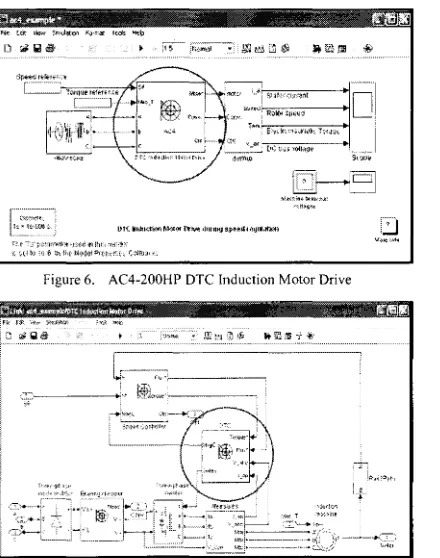
IIL AC4 S!MULINKMODEL
The AC4 model is a 200hp DTC induction motor drive model as shown in Fig. 6. Looking under mask of the DTC induction motor drive will show a part of block diagram of Fig. I. The DTC induction motor drive block contains the speed controller, voltage source inverter (VSI) and induction motor (IM) as shown in Fig. 7. The induction motor model can be referred to [7]. Looking under mask of the DTC block of Fig. 7, will show the switching table, flux and torque estimator and flux and torque hysteresis comparator as shown in Fig. 8. The switching table block is programmed to produce the voltage vector according to the switching table in Table I.
IV. FUZZY-PI BASED TORQUE CONTROLLER
Inside flux and torque hysteresis block of Fig. 8, there is flux hysteresis and torque hysteresis. This paper aimed to reduce the torque ripple. So, the torque hysteresis is reviewed before and after the addition of Fuzzy PI-Based Torque Controller.
tセ@ セ@.• :' セ[[\@ l'1"1'll•'t •! ,<'<' l!'l !t1I, 'r,( .j<>;
< '.-l 1 (•) '<) 6 !:<1 1'·( ti!•)<j?,i <>((·f;,·:"'. (. ( [Iャャセjj@ ••
Figure 6. AC4-200HP OTC Induction Motor Drive
Figure 8. Look under mask of OTC Induction Motor Drive
Referring to Fig. 8, the inputs of flux and torque hysteresis are reference torque (Torque*), reference flux (Flux*), calculated torque (Torque) and calculated flux (Flux). Looking under mask of the block diagram will show the two-level flux hysteresis comparator and the three-level torque hysteresis comparator (refer to Fig. 9) as described in previous section.
The proposed Fuzzy PI-based controller will use the similar strategy as the conventional flux and torque hysteresis block in classical DTC, but somehow there is an addition of Fuzzy PI-based Torque Controller before torque hysteresis block as shown in Fig. I 0.
Fig. 11 shows the Fuzzy PI controller block diagram. From Fig. 11, it can be seen the fuzzy PI controller has two inputs which is first; the torque error signal, TE =
t・Lイ・ヲセt・@ and second, the rate of change of torque error,
dTE = Tdt) - TE(t-/'it). Both inputs are being normalized (TEm dTt·n) using the input normalization gains G0 and G1
before being delivered into the fuzzy controller.
ᄋiMM⦅LNLL⦅セMセセMMBG|セ@
1 fol_h
·'T-.;::·-MMMMMMᄋセMGMMMMMMMMMGNZMBB[@
cAZ⦅セャMMM⦅⦅⦅NMMMセGセイセNセMMMMMMM⦅NNNMセ\⦅ZG|@
-
'
[image:3.598.25.231.69.238.2] [image:3.598.251.462.91.223.2] [image:3.598.27.247.436.715.2] [image:3.598.25.460.443.710.2]Figure 11. Fuzzy PI controller block diagram
where
G0: normalisation gain of torque error TE
G1: normalisation gain of rate of change of
torque error dT E
G2: unnormalisation gain of change of control
signal dTc
The output of the controller is a normalized change of control signal dTcn· The actual change of the control signal value dTc is obtained by using the output unnormalisation gain G2•
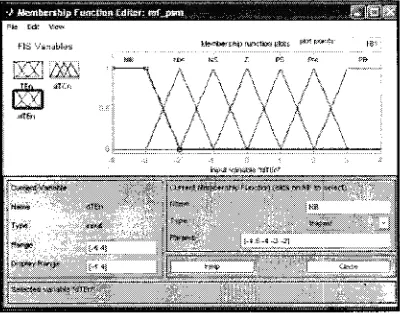
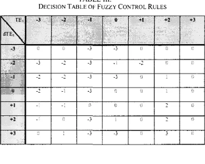
In the proposed controller, the universes of discourse (range) of the controller's inputs are divided into seven overlapping fuzzy subsets. The chosen normalized universe of discourse is defined from -3 to 3, and over this universe, seven fuzzy subsets are defined as shown in Table 2 and Fig. 12-14. A set of 49 rules that are designated to achieve the desired response are tabulated in Table 3.
TABLE IL
FUZZIFICA TION OF INPUT AND OUTPUT
Ll•bric Term .. \Sjmhi!J1· ·.
.. ·,t· < '/J'Y-. ;,<
pッウゥセQhᄋ@ Big PB
pッセャエャ|ャG@ \l;.:-Jitm1 P\1
pdセゥᄋョ・@ S.nall PS
Zt.>rn z
"
ᄋウ・ァ。セゥ|ZZ@ S;nall :\S
[G|M・ァセhゥ|ャG@ \fedhr:n '."\!
\:egatn-e Big 'OH
o.n.m;v,,,•
-
'!tn-""'
-
""'
Ptltft<flel-
'1-"1セュ^rセ@ 'f.<l.t;
"""''
Figure 12. Membership function editor for TE"
セ@ ,1/\ l\ /\ /\ /\ ,i
\ \/'- / \
- ' \ / \ /
'
y
\!
\1.,i \'i
\i
//'\
/\
/\
'\
/'\,
)/\
/
,.
\,; \I
\i " \Figure 13. Membership function editor for dT e,,
fNV\t
w.J
[image:4.595.253.460.77.247.2] [image:4.595.258.458.289.446.2] [image:4.595.256.460.494.654.2]TABLE III.
DECISION TABLE OF Fuzzy CONTROL RULES
セ@
-l . ·l!;::;
•I1::11
+t;, 7'.?.'
l:;f
.'
'""""'""" , " ""'
.3 ;. -j -3
:.·:-2
Nセ@ .}--
-)--,,,S_,J
--
-} :u 2 .;
+I
,,
+2 -3
+3 -3" -3
V. RESULT AND DISCUSSION
The parameters of the induction machine used in the simulation of classical DTC and fuzzy PI-based torque controller are given in Table 4. From the simulation, the resulting electromagnetic waveform of classical DTC and Fuzzy PI-Based torque controller is shown in Fig. 15 and Fig. 16 respectively. From both waveforms, it can be seen that classical DTC produced a peak-to-peak ripple of 220Nm while Fuzzy PI-Based, 80Nm. Thus, the electromagnetic torque ripple is minimized but with high ripple at the initial stage.
VI. CONCLUSION
There are two main problems associated with the implementation of hysteresis-based torque controller in the conventional DTC, which are high torque ripple and vanat10n in switching frequency. This paper has proposed the fuzzy PI-based torque controller to minimize the torque ripple. The topology of the fuzzy PI controller, and also the guideline of the controller gains' selection, had been thoroughly discussed. With the proposed torque controller, the torque ripple, especially at low speed is significantly reduced.
TABLE IV.
INDUCTION MOTOR PARAMETER
\lutu:.i.. ;11Ju.::t.:.u;>2
Figure 15. Electromagnetic torque waveform of classical direct torque controller
Figure 16. Electromagnetic torque waveform of Fuzzy Pl-Based torque controller
REFERENCES
[I] Takahashi, !., and Noguchi, T. "A new quick-response and high-efficiency control strategy of an induction motor," in IEEE Transactions on Industry Application. 1986. Volume. IA, No. 5,
Pages: 820-827.
[2] Habetler, T. G., Profumo, F. Pastorelli, M. and Tolbert, L. M. "Direct torque control of induction machines using space vector modulation," in IEEE Transactions on Industry Applications. 1992 Volume: 28, Issue: 5, Pages: 1045-1053.
[3] Depenbrock, M. "Direct self control of inverter-fed induction machine," in IEEE Transactions on Power Electronics. 1988.
Volume: 3, Issue: 4, Pages: 420 - 429.
[4] Toufouti, R., and Benalla, H., "Direct torque control for induction motor using fuzzy logic," in ACSE Journal. 2006. Volume: 6,
Issue: 2, Pages: 19-26.
[5] Toufouti, R., and Benalla, H., "Direct torque control for induction motor using intelligent techniques," in Journal of Theoritical and Applied In.formation Technology. 2007. Pages: 35-44.
[6] Sheidaei, F. Sedighizadeh, M. Mohseni-Zonoozi, S.H. Alinejad-Beromi, Y., "A fuzzy logic direct torque control for induction motor sensorless drive," in Universities Power Engineering
Conference. 2007. Pages: 197-202.
[image:5.597.27.238.81.250.2] [image:5.597.261.454.85.139.2] [image:5.597.27.239.543.709.2]