THE DEVELOPMENT OF COMPOSITE BODYWORK OF NOSE CONE PANEL FOR FORMULA VARSITY RACE CAR
MOHD HAFIDZ B. ZAKARIA
‘Saya akui bahawa telah membaca karya ini dan pada pandangan saya karya ini adalah memadai dari segi skop dan kualiti untuk tujuan penganugerahan Ijazah
Sarjana Muda Kejuruteraan Mekanikal (Automotif)’
Tandatangan : ………. Nama Penyelia I : ……….
THE DEVELOPMENT OF COMPOSITE BODYWORK OF NOSE CONE PANEL FOR FORMULA VARSITY RACE CAR
MOHD HAFIDZ B. ZAKARIA
Laporan ini dikemukakan sebagai memenuhi sebahagiaan daripada syarat penganugerahan Ijazah Sarjana Muda Kejuruteraan Mekanikal (Automotif)
Fakulti Kejuruteraan Mekanikal Universiti Teknikal Malaysia Melaka
“Saya akui laporan ini adalah hasil kerja saya sendiri kecuali ringkasan dan petikan yang tiap-tiap satunya saya telah jelaskan sumbernya”
iii
ACKNOWLEDGEMENT
Greatest thanks to Allah Almighty for giving me strength while doing this project. This project could not have been done without Mr. Nurfaizey Bin Abd. Hamid, who not only served as my supervisor but also encouraged and challenged me throughout my academic program. He patiently guided me through the study process, never accepting less than my best efforts. I want to express my gratitude to my friends, family and colleagues, whose support and good will kept me going through the project. My biggest thanks go to my project team, Muslim and Firdaus who always gave moral support in my difficult time. During the slow and often interrupted evolution of this project I have accumulated many debts, only a proportion of which I have space to acknowledge here. I am grateful to many people for help, both direct and indirect, in writing this technical report.
Thank you.
v
ABSTRACT
ABSTRAK
vii
CONTENTS
CHAPTER ITEMS PAGE
PENGAKUAN ii
DEDIKASI iii
ACKNOWLEDGEMENT iv
ABSTRACT v
ABSTRAK vi
CONTENTS vii
LIST OF TABLES x
LIST OF FIGURES xi
LIST OF SYMBOLS xiv
LIST OF APPENDICES xv
CHAPTER I INTRODUCTION
1.1 Background of Project 1
1.2 Project Significant 2
1.3 Problem Statement 2
1.4 Objectives 3
1.5 Scopes 3
1.6 Planning and execution task 4 1.6 Summary of Technical Report 6
CHAPTER II LITERATURE REVIEW
CHAPTER ITEMS PAGE
2.2 Fiber reinforced composite 7 2.2.1 Glass fiber 10 2.2.2 Matrix material 12 2.3 Fabrication of composite part 12 2.3.1 Hand lay-up 13
2.4 Testing method 14
CHAPTER III METHODOLOGY
3.1 Introduction 16
3.2 Project activities 16
3.3 Finding information 17
3.4 Design 18
3.4.1 Analysis of problem 20 3.4.2 Conceptual design 20 3.4.3 Selected scheme 22
3.4.4 Detailing 22
3.4.5 Working drawing 23
3.5 Flexural test 24
3.6 Fabrication process 26
3.6.1 Plug making 27 3.6.2 Mold making 33 3.6.3 Finish product 37
CHAPTER IV RESULT
4.1 Flexural testing 40
4.1.1 Specimen selection 41
ix
CHAPTER ITEMS PAGE
CHAPTER V DISCUSSION
5.1 Fabrication Problem 46 5.1.1 Mould problem 47 5.2 Comparison between actual end
product and design
52
CHAPTER VI CONCLUSION 53
REFERENCES 54
BIBLIOGRAPHY 56
LIST OF TABLES
NO. TITLE PAGE
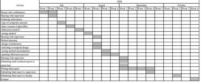
1.1 Gantt chart for PSM I 4
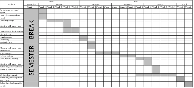
1.2 Gantt chart for PSM II 5
2.1 Comparative yarn properties for fiber reinforcement for plastic
(Source: Smith & Hashemi, 2006)
8
3.1 Design matrix 22
3.2 Design requirement for nose cone panel 23 3.3 Specimen parameters for flexural test 24
4.1 Flexural Testing Result 40
5.1 Comparison of dimension between design and actual product
xi
LIST OF FIGURES
NO. TITLE PAGE
1.1 Section of outer panel Formula Varsity Race Car
1
2.1 Compression-molded SMC trunk of Cadillac Solstice [3]
9
2.2 Woven roving fiberglass [5] 11 2.3 Chopped strand mat fiberglass [6] 11 2.4 Chopped strand fiberglass [5] 11
2.5 Hand lay-up process [10] 14
2.6 Flexural test arrangements in three-point bending. [3]
15
3.1 Flow of project activities 17
3.2 Block diagram of design process 19
3.3 First conceptual design 20
3.4 Second conceptual design 21
3.5 Third conceptual design 21
3.6 Schematic diagram of nose panel 23
3.7 Specimen 25
3.8 Instron 5585 25
3.9 Testing on specimen 26
3.10 Hand lay-up process 26
3.11 Dry foam 27
3.12 Latex glue 27
3.13 Sand paper 27
3.14 Brush 27
NO. TITLE PAGE
3.16 Mounting board 27
3.17 White floor cement 28
3.18 Scrapper 28
3.19 Automotive poly putty 28
3.20 Thinner 28
3.21 Scissor 28
3.22 Undercoat paint spray 28
3.23 Section cut 29
3.24 Cutting section cut 29
3.25 Plywood with bottom view 30
3.26 Pasting foam on plywood 30
3.27 Complete applying foam 31
3.28 Sanding foam 31
3.29 Applying white floor cement 32 3.30 Applying automotive poly putty 32
3.31 Plug after finish sanded 33
3.32 Roller 33
3.33 Brush 33
3.34 CSM Fiberglass 34
3.35 Polyester resin 34
3.36 Release wax 34
3.37 MEKP hardener 34
3.38 Scrapper 34
3.39 Applying release wax 35
3.40 Applying first layer of fiberglass 35
3.41 Applying resin 36
3.42 Removing air bubble using roller 36
3.43 Remove mould from plug 37
3.44 Applying release wax 37
3.45 Applying first layer of fiberglass 38 3.46 Applying resin on the fiberglass 38
xiii
NO. TITLE PAGE
4.1 Side view of drawing 42
4.2 Side view of actual product 42
4.3 Top view of drawing 43
4.4 Top view of actual product 43
5.1 Fabrication problem 44
5.2 Dried edge in mould making 45
5.3 Bump at mould surface 46
5.4 Air bubbles 47
5.5 Mould after disassemble from plug 48
5.6 Crack on the mould 49
LIST OF SYMBOLS
� = Flexural strength
Pmax = maximum load at failure
b = specimen width
h = specimen thickness
xv
LIST OF APPENDICES
NO. TITLE PAGE
A Detail drawing 56
B Specimen data for flexural test 57 C Chopped Strand Mat Description 58
D Woven Roving Description 59
CHAPTER I
INTRODUCTION
1.1 Background of Project
[image:18.595.217.458.489.650.2]Formula Varsity Race Car is constructed by student from Faculty of Mechanical for Formula Varsity Race each year between the local universities in Malaysia. The outer panel of the car is divided into two sections. Front section is called as nose cone while the middle section is called side port as shown in the Figure 1 below.
Figure 1: Section of outer panel Formula Varsity Race Car [1]
This project is actually involved with the nose cone panel only. The construction of the new nose cone panel will consider the following factors:
2
i. Material quality which determine the lifetime of the panel. ii. Aerodynamic effect to enhance the speed performance. iii. Manufacturing process which limited by the cost of the
manufacturing and the ability to manufacture it.
If compare to Formula Student car that been made by university from other country, it has already used composite material. The bodywork also has achieved a high standard of quality. So, the development that will be made through this project will open a new potential to experience the new type of material for bodywork of Formula Varsity race car which using composite material instead of using sheet metal.
1.2 Project Significant
This project will result to the development of the nose cone panel for Formula Varsity Race Car. The new composite material used in the fabrication will replace old method of fabrication which is use sheet metal. The composite material will give a lot more advantages compare to sheet metal. In design aspect, old design will be replace by this new design which has more aerodynamic effect and also good looking. Furthermore, the composite material that will be used will provide weight reduction to the total weight of race car. Through this project, there are chance to explore in composite manufacturing. The new panel that used composite material will be used in the next construction of Formula Varsity Race Car after this.
1.3 Problem Statement
difficult to shape. This project is about the development of the composite bodywork for nose cone panel using glass fiber polyester laminates.
1.4 Objectives
The objective of this project is to develop nose cone panel for Formula
Varsity race car by using composite material which is glass fiber polyester laminated.
1.5 Scope
There are five scopes in this project in order to achieve the project objective.
a. Study about the types of fiberglass and the method that already been used in fabrication of fiberglass. The study also includes the principle theory of fiberglass and the latest development in fiber glassing.
b. To create design of nose cone panel using computer aided drawing software. The design must include aerodynamic effect.
c. Find the right method for fabrication process based on normally used method or create new method as long as all the criteria are achieve.
d. Analysis of flexural test is needed in order to prove that which method will give an appropriate result.
4
[image:21.792.71.730.176.444.2]1.6 Planning and execution task
Table 1.1: Gantt chart for PSM I
Week 1 Week 2 Week 3 Week 4 Week 5 Week 1 Week 2 Week 3 Week 4 Week 1 Week 2 Week 3 Week 4 Week 5 Week 1 Week 2 Week 3 Week 4 Project title confirmation
Meeting with supervisor Gathering information -type of composite material -basic concept of glass fiber -fabrication method -testing method Meeting with supervisor Method planning -design consideration -sketching conceptual design -testing method determination -planning fabrication process Meeting with supervisor
Writing final report
Submitting final report to supervisor Submitting final report to faculty Seminar
Activity
Submitting draft technical report to supervisor
2008
Table 1.2: Gantt chart for PSM II
Week 1 Week 2 Week 3 Week 4 Week 5 Week 1 Week 2 Week 3 Week 4 Week 1 Week 2 Week 3 Week 4 Week 1 Week 2 Week 3 Week 4 Week 1 Week 2
Detailing design Flexural Test -create sample -do testing -analysis data Fabrication -Plug making -Mould making -End product making
Writing final report
Submitting final report to faculty
Correction to detail design
Meeting with supervisor
Meeting with supervisor Submitting draft technical report to supervisor
April 2009
2008
Week 1-4
March
Activity November December January February
Submitting final report to supervisor
Revision on previous report
Correction on previous report
Meeting with supervisor
6
1.7 Summary of technical report
CHAPTER II
LITERATURE REVIEW
2.1 COMPOSITE MATERIAL
Smith and Hashemi [2] defined the definition of composite as below:
“A composite material is a material system composed of a suitably arranged mixture or combination of two or more micro- or macro constituent with an interface separating them that differ in form and chemical composition and are essentially insoluble in each other”.
Today, the most common man-made composites can be divided into three main groups which are Polymer Matrix Composites (PMC’s), Metal Matrix Composites (MMC’s) and Ceramic Matrix Composites (CMC’s).
![Figure 1: Section of outer panel Formula Varsity Race Car [1]](https://thumb-ap.123doks.com/thumbv2/123dok/632907.76692/18.595.217.458.489.650/figure-section-of-outer-panel-formula-varsity-race.webp)