UNIVERSITI TEKNIKAL MALAYSIA MELAKA
DEVELOPMENT OF MOBILE HEAT DETECTING DEVICE
FOR COOLING TOWER
This report submitted in accordance with requirement of the Universiti Teknikal Malaysia Melaka (UTeM) for the Bachelor of Mechanical Engineering Technology
(Maintenance Technology) (Hons.)
by
TENGKU ZAHARIN BIN TENGKU ZAINAL
B071110314
891231-01-5093
i
ABSTRAK
ii
ABSTRACT
iii
DEDICATION
iv
ACKNOWLEDGEMENT
I would like to express my gratitude to my supervisor, Mr. Muhamad Azwar bin Azhari, whose expertise, understanding, and patience, added considerably to my graduate experience. I appreciate his vast knowledge and skill in many areas (e.g., vision, aging, ethics, interaction with participants), and his assistance in writing reports. I would like to thank the other members of my classmates for the assistance they provided at all levels of the research project.
v
2.2.4.1 Cooling Tower Process 15
2.3 Fouling 16
2.3.1 Particulate Fouling 17
2.3.2 Crystallization or Preciptation Fouling 17
vi
2.3.4 Corrosion Fouling 18
2.3.5 Biological Fouling 19
2.3.6 Solidification or Freezing Fouling 19
2.3.7 Fouling Process 19
2.5.6 Impurities and Suspended Solids 24
2.6 Heat Detecting Device 25
3.3 Material and Device Selection 37
3.3.1 Mobile Device 38
3.3.2 Material Selection of Mobile Device 39 3.3.2.1 V262 RC Quadcopter Mobile Device 40 3.3.3 Material Selection of Mounting 41
3.3.4 Selection of Fasteners 42
3.3.5 Heat Sensor Device 42
3.3.5.1 Thermocouple Device 43
3.3.5.2 Thermography Device 44
3.4 Fabricating Mounting 45
vii
CHAPTER 4: RESULT & DISCUSSION 50
4.1 Design of Thermocouple Mounting 50
4.2 Mounting of Thermocouple Sensor 51
4.3 Temperature Measurement Data 52
4.3.1 Data of Thermography Device 53
4.3.2 Data of Thermocouple Device 56
4.3.3 Temperature Distribution Mapping 57
CHAPTER 5: CONCLUSION & FUTURE WORK 61
5.1 Conclusions 61
5.2 Future Work 62
REFERENCES 63
APPENDICES
A Pliminary Design 1 B Pliminary Design 2
viii
LIST OF TABLES
2.1 Comparison of induced draft and forced draft 13 2.2 Annual cost estimation of fouling in some countries 21 2.3 Standard for thermocouple types, temperature range and accuracy 26 2.4 Overview of heat sensor device for a certain heat exchanger types
by different researchers
29
2.5 Advantages and disadvantages of of RC Helicopter and RC Quadcopter
33
3.1 Characteristics of RC Quadcopter 38
3.2 Mechanical properties of acrylonitrile butadiene styrene (ABS) 39 3.3 Properties and specification of polystyrene material 40 3.4 Features and specifications of V262 Cyclone RC Quadcopter 41 3.5 Mechanical properties of Aluminium Alloy 6061 42 3.6 Features and specification of HIOKI Temperature Logger
LR5011
44
3.7 Features and specifications of Fluke Ti27 thermography device 45
ix
LIST OF FIGURES
1.1 Forced draft and Induced draft of cooling tower air flow 3 1.2 Fouling occurred at the outside of the tubes 4
2.1 Shell and tube heat exchanger flow 9
2.2 Spiral heat exchanger flow 9
2.3 Fin fan cooler air flow t 10
2.4 Fin fan cooler’s hot air flow rise upwards 11
2.5 Air flow through cooling tower 14
2.6 Spray-fill, counterflow cooling tower 15
2.7 Typical splash-type fill 16
2.8 Fouling processes 20
2.9 Particulate fouling curves for different Ts values 22 2.10 The thermal image of surface wall temperature distributions for
air cooler condenser
28
3.1 Mobile heat detecting device flow chart 36 3.2 Design idea of RC Quadcopter with video camera 37
3.3 V262 RC Quadcopter mobile device 34
3.4 Thermocouple sensor device (HIOKI Temperature Logger LR5011)
43
3.5 Fluke Ti27 thermography device with thermal image distribution 45
3.6 Removeable fasteners assembled 46
3.7 Lighten mounting of thermocouple device 46 3.8 Installing thermocouple device inside the mounting 47 3.9 Measuring technique and infrared image of thermography 48
4.1 3D bottom view of assembled thermocouple mounting with RC Quadcopter
50
x
4.3 Position of the cooling tower 53
4.4 Temperature distribution mapping by using thermography device 58 4.5 Temperature distribution mapping by using thermocouple device
with RC Quadcopter
xi
LIST OF ABBREVIATIONS, SYMBOLS AND
NOMENCLATURE
.BMP - Filename Extension Of Digital Photography .IS2 - Format Of Thermal Image
.JPG - Filename Extension Of Digital Photography ABS - Acrylonitrile Butadiene Styrene
1
1.1 Heat Exchanger
Heat exchangers are device that transfer or remove heat between two fluids using hot and the cold fluid. The heat transfer process accomplished by conduction from the hot fluid to the tube wall and convection from hot fluid to cold fluid (Geankoplis, 1993). The fluid medium is separated by a solid wall to prevent both fluid from mixing. The types of heat exchangers are double pipe heat exchanger, shell and tube heat exchanger, fin fan cooler and also cooling tower.
Double pipe heat exchanger is the simplest types of heat exchanger which use one pipe within another larger pipe. The hot fluid flow inside a pipe and the cold fluid flows in another pipe that surrounds the pipe with hot fluid. Double pipe heat exchanger can be operated in parallel flow when cold fluid and hot fluid is in parallel direction and in counter flow when direction of both fluids is not same. This design of heat exchanger is not complex and less requirement of maintenance need makes double pipe heat exchanger suitable for small industry.
Another type of heat exchanger is shell and tube heat exchanger which is commonly used in large industry like oil refineries and chemical process. This heat exchanger consists of a shell that contain with a bundle of tubes inside it. One fluid flows through the tubes, and other fluid flows over the pipes and through the shell to
INTRODUCTION
2 transfer heat between the two fluids. It is suitable for high pressure application due to the shape and big size.
Meanwhile, fin fan cooler is a device to reduce the hot fluid which is gas, water or even oil by using fans and with the addition of the fin. This equipment transfers heat from the fluid to the ambient air. Basically, this equipment designed with multiple rows of finned tubes in a series of surface and required numbers of fans. Fins are normally used from aluminium material due to good thermal conductivity and easy to fabricate. Unlike the other types, fin fan cooler did not use water as the cooling medium, but uses the air flow to reduce the heat with the helps of fin and fan. Other terms for fin cooler is air fin cooler, coil cooler and also air cooled heat exchanger. Fin fan cooler may be forced draft or induced draft types.
Same like other types of heat exchanger, cooling tower is a device to reject heat or cooling of a water stream to a lower temperature which draw out waste heat to the upwards. Evaporation process occurs in the cooling tower operation when a small portion of water being cooled is allowed to evaporate into a moving air flow to provide better cooling effect. High temperature of air is and and 100% of relative humidity produced when the heat from the inlet water stream rejected to upwards of cooling tower (Yahya, 2006). In HVAC (heating, ventilating, and air conditioning) application, cooling tower used to dispose or reject unwanted heat from a chiller.
1.2 Cooling Tower Draft
3 Forced draft gives more benefits than induced draft in maintainability, power, cost and space. But the need of specification depends on the workplace situation and environment. For example, in an industrial plant, induced draft fan is generally preferred from forced draft which forms more hot air circulation. However, this potential exposes maintenance group to hot air and huge resistance. In 1950, the serious problem of heat exchanger is the hot air recirculation occurring at the inlet (Gunter & Shipes, 1971). According to Gunter and Shipes (1971), by using a smoke test showed that induced draft creates more outlet air flow better than the forced draft due to blockage of the fan and motor which is produced hot air circulation.
Figure 1.1 Forced draft and Induced draft of cooling tower air flow (Hensley, 2009).
1.3 Cooling Tower Process
4 that contains all those tiny droplets in order to fall through a mechanically induced, upward moving stream of air.
In order to increase the contact time between air and water, the installation of fills inside cooling tower is implemented. This technique can obstruct or impede the progress of falling water which is depicted in Figure 2.7. This part is located in the horizontal area below the sprays of the tower and above the air inlet level. In staggered rows, these fills or splash bars slow down the falling water and at the same time increase the surface area exposed to the air and boosting the process of evaporation (Morvay & Gvozdenac, 2008).
1.4 Problem Statement
The most common problem in heat exchanger cooling tower operation is fouling. Fouling is the accumulation of unwanted particle which is not only occur inside of the tubes, but also out of the tubes (Ezgi et al., 2014). There are many effects of fouling that could disturb the output of temperature and air flow and also can contaminate the environment.
Figure 1.2 Fouling occurred at the outside of the tubes (Tucker, 2012).
5 air flow rate. Figure 1.2 proved the outside fouling decrease the air flow rate due to the blockage at the fins.
The common ways to detect faults in the heat exchanger is by measure the heat transfer coefficient, pressure drop and air flow rate (Shah et al., 2009). Apparently, by monitoring the temperature by using sensing device, the heat transfer condition can be detected. Today, maintenance is important to every industry for prolonging the equipment or machine. Condition based maintenance is one of the predictive maintenance, which is depend on continuous condition monitoring equipment or in the other words sensing device to detect the sign of failure. (Kothamasu et al., 2006) stated that condition based maintenance task is performed to detect incipient failures long before their occurrence. For monitoring cooling tower, thermocouple is used as a sensing device. Measuring method using thermocouple devices requires the maintenance crew to approach the cooling tower which is extremely hot. Exposing to high temperature will cause burns to the skin of the maintenance crew. Moreover, if the cooling tower is in forced type, the air outlet is low in air velocity and heat rather than induced type which creates hot hot air circulation spread hot air to the surrounding. The existing method risk the safety of the maintenance crew in both of the draft type.
6
1.5 Objectives
Based on the problem statement stated above, the objectives of this study are stated below:
i. To develop a mobile carrier detecting device to monitor and measure the surface temperature.
ii. To differentiate the accuracy of different heat sensors device by using mobile (thermocouple) and manual measuring (thermography).
1.6 Scopes
In order to reach the objectives, a few scopes have been stated:
i. Developing a mobile carrier detecting device using a radio control quadcopter and heat sensor.
ii. Using mobile device to carry thermocouple for measuring surface temperature of the cooling tower surface.
7
2.1 Condition Based Maintenance
Maintenance is an important to every industry for prolonging the equipment or machine. Maintenance is an organized activity to keep an item in its best operational condition with the lowest cost. In the fin fan cooler, fouling is difficult to detect, uninterruptible process, and expensive overhaul. Due to the facts, predictive maintenance is the suitable type to detect the condition of equipment and reducing the risk of failure. Condition based maintenance is one of the predictive maintenance, which is depending on continuous condition monitoring equipment or in the other words sensing device to detect the sign of failure. (Kothamasu et al., 2006) stated that condition based maintenance task is performed to detect incipient failures long before their occurrence.
To maintain the performance of the heat exchangers, condition based maintenance is the best maintenance type activity for optimizing output of equipment. Condition of heat exchanger cannot be done with only through visualization because fouling not only appear on outside of tubes, but also inside of the tubes. Thus, specific device is needed as an alternative method to measure the changes of temperature, pressure and air flow to detect if there any fouling occur on the systems.
LITERATURE REVIEW
8
2.2 Heat Exchangers
Heat exchangers are device that transfer heat between two fluids using hot and the cold fluid. The heat transfer process accomplished by conduction from the hot fluid to the tube wall and convection from hot fluid to cold fluid (Geankoplis, 1993). In other words, the purpose of heat exchangers is to reduce the fluid temperature. The main feature of the heat exchanger is for cooling gas or liquid from approximately 80 to 26 degrees Celsius (Veldman et al., 2011). Application of heat exchangers is extensively applied for application, including heating and air conditioning, power production in large plant and chemical processing. More types of heat exchangers designed these days, however the familiar types tend to be shell and tube heat exchanger, fin fan cooler, double pipe heat exchanger and spiral heat exchanger.
2.2.1 Shell and Tube Heat Exchanger
9 Figure 2.1 Shell and tube heat exchanger flow.
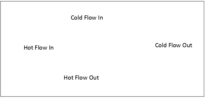
2.2.2 Spiral Heat Exchanger
Spiral Heat Exchangers or (SHE) is a placement of coiled tube, along with two partitions coiled one around the other. These two channels run in a counter-flow design, providing outstanding turn down ratios, while optimizing stream patterns which in turn to improve heat transfer. An additional, Spiral Heat Exchanger not require larger space like conventional Heat Exchanger. An extra-large Spiral Heat Exchanger has other benefits, which includes a reduction in occurrence of pressure decrease, greater thermal efficiency and lowering in overall energy costs. The flow of both fluid for this type of heat exchanger is described in Figure 2.2.
Figure 2.2 Spiral heat exchanger flow.
Cold Flow In
Cold Flow Out
10
2.2.3 Fin Fan Cooler
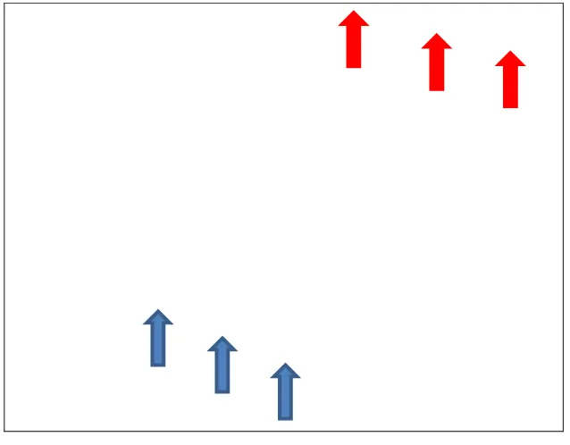
Fin fan cooler is a device to greatly reduce hot fluid which is gas, water or even oil by applying fans and together with the addition of the fin which is covering the tube. This kind of equipment transport heat from the fluid towards the ambient air. Essentially, fin fan cooler designed with multiple rows of finned tubes within a sequence of surfaces and numbers of fans needed. Fins are generally from aluminium material because of good thermal conductivity and easy to fabricate. In contrast to the other types, fin fan cooler unit did not use water as the cooling medium, but uses the air flow to minimize the heat with the helps of fin and fan. Other terms for fin cooler is air fin cooler, coil cooler and also air cooled heat exchanger. Convection, conduction, and radiation process is occurred when heat exchangers operated. The flow of the ambient air which is forced to up sight due to cooling tubes is explained in Figure 2.3.
Figure 2.3 Fin fan cooler air flow.
11 flow applied which is described in Figure 2.4. According to Yunus & Michael, the increasing of fluid motion, the better convection heat transfer achieves. Direct contact of wall part with another nearest part will transfer energy which is the heat transfer of the convection process (Kukurugaya et al., 2011). The part which is in contact is including the wall to the fluid due to flowing fluid in the tubes. The conduction at the area is affected by contact pressure, and two surface roughness.
Another process involves in fin fan cooler is conduction and radiation. The heat transfer of material along the tubes and fins is the conduction process. Radiation is the heat transfer method that can take place in a vacuum, although it can take place in a material medium. A hot body produces energy that is beyond the red end of the visual spectrum. The application of fin fan cooler is widely used in refinery, refrigeration plants, air conditioning and car radiators.
Figure 2.4 Fin fan cooler‟s hot air flow rise upwards (Jain et al., 2012).
Creating an air cooler heat exchanger depends on the customer preferences, installation, power need and several configurations. There are two types of air cooler, which is vertical and horizontal. The common type is the horizontal type that create vertical air flow with horizontal fan. Fin fan cooler may be forced draft or induced draft types. In forced draft type, the fan is located below the fin tube, but induced draft fan is installed on the tube section.
12 environment. For example, in offshore platform, induced draft fan is generally preferred from forced which forms more hot air circulation. However, this potential exposes maintenance group to hot air and huge resistance. In 1950, the serious problem of fin fan air cooler is the hot air recirculation occurring at the inlet (Gunter & Shipes, 1971). One of the methods to detect the hot air circulation is by using the smoke test method as a useful visual tool. The test method shows induced draft creates more outlet air flow than the forced draft due to the location of the fan position. Forced draft not have high outlet air flow due to the fan installed under the tube bundle. Different features of induced draft and forced draft air cooled heat exchangers is described in Table 2.1.