ISLANDING DETECTION AND CLASSIFICATION AND LOAD SHEDDING SCHEME FOR DISPERSED GENERATION INTEGRATED
RADIAL DISTRIBUTION SYSTEMS
AZIAH KHAMIS
THESIS SUBMITTED IN FULFILMENT OF THE DEGREE OF DOCTOR OF PHILOSOPHY
FACULTY OF ENGINEERING AND BUILT ENVIRONMENT UNIVERSITI KEBANGSAAN MALAYSIA
BANGI
PENGESANAN DAN PENGKELASAN KEPULAUAN DAN SKIM PENYISIHAN BEBAN BAGI SISTEM PENGAGIHAN
JEJARI TERSEPADU PENJANA TERAGIH
AZIAH KHAMIS
TESIS YANG DIKEMUKAKAN UNTUK MEMPEROLEH IJAZAH DOKTOR FALSAFAH
FAKULTI KEJURUTERAAN DAN ALAM BINA UNIVERSITI KEBANGSAAN MALAYSIA
BANGI
iii
DECLARATION
I hereby declare that the work in this thesis is my own except for quotations and summaries which have been duly acknowledged.
3 Nov 2014 AZIAH KHAMIS
iv
ACKNOWLEDGMENTS
First and foremost praise be to Almighty Allah for all His blessings for giving me perseverance and good health throughout the duration of this PhD research.
I would like to express sincere appreciation for the intelligent advice, encouragement and guidance of my main supervisor, Assoc. Prof. Dr. Hussain Shareef. Without his tireless assistance, leadership, and confidence in my abilities, this thesis would not come to its timely completion.
Furthermore, I would like to express my high appreciation to my co-supervisor Prof. Dr. Hjh. Azah Mohamed for the valued knowledge, ideas, encouragement, assistance and support received from her during my PhD program.
I would like to acknowledge the financial support from Ministry of Higher Education, Universiti Teknikal Malaysia Melaka and also Universiti Kebangsaan Malaysia for making it possible for me to pursue and complete my PhD degree.
I would like to thank all Power System Research group UKM for their help, friendship, and creating a pleasant working environment throughout my years in UKM. My heartfelt appreciation goes to all my special friends, especially Hazilah Abdullah and Abdul Zaini Abdullah for their inseparable support and prayers.
To my dearest husband, Ahmad Zulkarnain Rosli, thanks for your do’as,
v
ABSTRACT
The high penetration level of distributed generation (DG) provides numerous potential environmental benefits, such as high reliability, efficiency, and low carbon emissions. However, the effective detection of islanding and rapid DG disconnection is essential to prevent safety problems and equipment damage caused by the island mode operations of DGs. The common islanding protection technology is based on passive techniques that do not perturb the system but have large nondetection zones. Therefore, the first part of this thesis attempts to develop a simple and effective passive islanding detection method with reference to a probabilistic neural network-based classifier, as well as utilizes the features extracted from three-phase voltages seen at the DG terminal. This approach enables initial features to be obtained using the phase-space technique. This technique analyzes the time series in a higher dimensional space, revealing several hidden features of the original signal. Meanwhile, the second part of the thesis focuses on the development of an optimal load shedding scheme after the system experiences an unintentional islanding state to prevent system collapse due to load-generation mismatch and voltage instability encountered in the islanded part of the system. To handle this optimization problem, a constraint multiobjective function that considers the linear static voltage stability margin and amount of load curtailment was formulated. A novel heuristic optimization technique based on the backtracking search algorithm (BSA) was subsequently proposed as an optimization tool for determining the optimum load shedding based on the proposed objective function. Several test systems, including a radial distribution system with two DG units and the Institute of Electrical and Electronics Engineers (IEEE) 33-bus radial distribution system with four DG units, were utilized to evaluate the effectiveness of the proposed islanding detection method and the optimal load shedding scheme. The effectiveness of the proposed islanding detection method was verified by comparing its results with the conventional wavelet transform (WT)-based technique through intensive simulations conducted with the DIgSILENT Power Factory® software. The assessment indices, namely, the mean absolute percentage error (MAPE), mean absolute error (MAE), and root mean square error (RMSE), obtained a 0% error rate for the proposed method when applied to the IEEE 33-bus radial distribution system with four DG units. Meanwhile, the MAPE,
vi
ABSTRAK
vii
TABLE OF CONTENTS
Page
DECLARATION iii
ACKNOWLEDGMENTS iv
ABSTRACT v
ABSTRAK vi
CONTENTS vii
LIST OF TABLES x
LIST OF FIGURES xii
LIST OF ABBREVIATIONS xv
LIST OF SYMBOLS xvii
CHAPTER I INTRODUCTION
1.1 Research Background 1
1.2 Problem Statement 4
1.3 Objective of the Research 6
1.4 Scope of the Research 6
1.5 Organization of the Thesis 7
CHAPTER II LITERATURE REVIEW
2.1 Islanding Detection Methods 8
2.1.1 Central Islanding Detection Techniques 9 2.1.2 Review of the Conventional Local Islanding Detection 12
Technique
2.1.3 Review of the Intelligent Local Islanding Detection 16 Technique
2.2 DG Models for Islanding Detection 23
2.3 Load Shedding Schemes 25
2.3.1 Review of Under-Frequency Load Shedding Schemes 26 2.3.2 Review of Under-Voltage Load Shedding Schemes 29
2.4 DG Models for Optimal Load Shedding 33
viii
2.6 Chapter Summary 36
CHAPTER III ISLANDING DETECTION USING PHASE-SPACE AND NEURAL NETWORK
3.1 Introduction 38
3.2 Tools and Methods used in the Proposed Method 39
3.2.1 Phase-Space Technique 39
3.2.2 Probabilistic Neural Network 41
3.3 Proposed Islanding Detection Method 44
3.3.1 Data Collection 44
3.3.2 Phase-Space Feature Extraction 45
3.3.3 Design of Artificial Intelligent Classifier 47
3.4 Performance Evaluation Methods 52
3.4.1 Performance Evaluation of Conventional Method 52 3.4.2 Performance Evaluation with Statistical Indices 54
3.5 Chapter Summary 55
CHAPTER IV OPTIMAL LOAD SHEDDING SCHEME USING BACKTRACKING SEARCH ALGORITHM
4.1 Introduction 56
4.2 Tools and Methods Used in Proposed Load Shedding Scheme 56
4.2.1 Voltage Stability Margin 56
4.2.2 Backtracking Search Optimization Algorithm 58 4.2.3 Newton–Raphson Power Flow Solution 61 4.3 Problem Formulation for Optimal Load Shedding Scheme 62
4.3.1 Operational Constraints 63
4.3.2 Fitness Function 64
4.3.3 Application of BSA for Optimal Load Shedding 65 Scheme
4.4 Performance Evaluation Scheme 69
4.4.1 Performance Evaluation with Conventional GA 69 Method
4.5 Chapter Summary 71
CHAPTER V RESULTS AND DISCUSSION
5.1 The Test System for Islanding Detection 72
ix
Units 72
5.1.2 IEEE 33-Bus Radial Distribution System with Four 73 DG Units
5.2 Test Results of the Radial Distribution System with Two 74 Identical DG Units
5.2.1 Input Feature Extraction 76
5.2.2 Results of RBFNN with Phase-Space Features 78 5.2.3 Results of RBFNN with Wavelet Transform Features 79 5.2.4 Results of PNN with Phase-Space Features 80 5.2.5 Results of PNN with Wavelet Transform Features 81 5.2.6 Summary of the Result Obtained for All of the Tested 81
Islanding Detection Methods
5.3 Implementation of Islanding Detection on The IEEE 33-bus 84 Radial Distribution Systems with Four DG Units
5.3.1 Input Features Extraction 85
5.3.2 Results of RBFNN with Phase-Space Features 88 5.3.3 Results of RBFNN with Wavelet Transform Features 89 5.3.4 Results of PNN with Phase-Space Features 90 5.3.5 Results of PNN with Wavelet Transform Features 91 5.3.6 Summary of Islanding Detection Analysis 91 5.4 Description of the Test System for Optimal Load 93
Shedding Scheme
5.5 Test Results of Optimal Load Shedding Scheme 96
5.5.1 Optimal Load Shedding for Island A Using BSA 99 5.5.2 Optimal Load Shedding for Island A Using GA 106 5.5.3 Optimal Load Shedding for Other Islanded Systems 113 5.5.4 Summary of Load Shedding Scheme 124
5.6 Chapter Summary 125
CHAPTER VI CONCLUSIONS AND RECOMMENDATIONS
6.1 Overall Conclusions 126
6.2 Significant Contributions of the Research 128
6.3 Recommendations for Future Studies 129
REFERENCES 130
APPENDIXES
A IEEE 33-Bus Radial Distribution System 140
B Wavelet Technique as Features Extraction 141
x
LIST OF TABLES
Table Number Page
2.1 Summary of remote islanding detection techniques 12 2.2 Comparison of passive islanding detection techniques 13 2.3 Comparison of active islanding detection techniques 15
2.4 Utilization of SP in islanding detection 20
2.5 Utilization of the AI classifier in islanding detection at DG 23 2.6 Comparison of various computational intelligence load
shedding schemes
33
3.1 Classifier output definition 45
3.2 Selected phase-space features 45
3.3 A scale of judgment of forecasting accuracy 55
5.1 System model description 72
5.2 DG installed node with operating points 74
5.3 Number of samples for training and testing 76
5.4 Parameter settings of the RBFNN and PNN classifiers for DG1 and DG2
77 5.5 RBFNN classification results with phase-space features 79 5.6 RBFNN classification results with wavelet transform
features
80 5.7 PNN classification results with phase-space features 81 5.8 PNN classification results with wavelet transform features 81 5.9 Comparison of PNN classifier performance with phase-space
and wavelet features
82 5.10 Comparison of MAPE, RMSE, and MAE for various
islanding detection methods
83 5.11 Number of samples for training and testing at IEEE 33 bus
system
85 5.12 Parameter settings of the RBFNN and PNN classifiers for
DG1, DG2, DG3, and DG4
88 5.13 RBFNN classification results with phase-space features 88 5.14 RBFNN classification results with wavelet transform
features
xi
5.16 PNN classification results with wavelet transform features 91 5.17 Comparison of PNN classifier performance with phase-space
and wavelet feature
92 5.18 Comparison of MAPE, RMSE, and MAE for various
islanding detection methods
92
5.19 Rated maximum power of DGs 93
5.20 Percentage load priority limits for the IEEE 33-bus radial distribution system
94 5.21 Overall power demand and supply in islanded system 96
5.22 GA and BSA parameter settings 96
5.23 Amount of hourly load curtailment at individual buses in island A
103 5.24 Summary of load shedding performances at hour 9.00 113 5.25 Summary of load shedding performances at hour 15.00 117 5.26 Amount of hourly load curtailment at individual buses in
island B
121 5.27 Amount of hourly load curtailment at individual buses in
island C
122 5.28 Amount of hourly load curtailment at individual buses in
island D
123 5.29 Performance of BSA and GA in terms of fitness, VSM, and
amount of load curtailment at hour 9.00
124 5.30 Performance of BSA and GA in terms of fitness, VSM, and
amount of load curtailment at hour 15.00
xii
LIST OF FIGURES
Figure Number Page
1.1 (a) Traditional distribution system, (b) generation embedded distribution system
2
1.2 Power islanding condition 2
1.3 Voltage and frequency response 3
2.1 Classification of islanding detection technique 9
2.2 Remote islanding detection technique 9
2.3 Transfer trip scheme 11
2.4 Basic block of intelligent islanding detection technique and classification
16
2.5 Block diagram of the inverter 24
2.6 Schematic diagram of mini hydro power for grid connected operation
24
2.7 Types of load shedding schemes 25
2.8 Generator model 34
2.9 System for load shedding 35
2.10 Simplified illustration of the concept behind three types of power distribution configuration
36
3.1 Architecture of a PNN 43
3.2 Phase-space feature extraction, (a) three-phase fault, (b) Euclidean norm (Ex) of the fault signal in (a), (c) selected region of Euclidean norm (Ex) for feature selections, and (d) Euclidean norm (Ex) and its features of the fault signal in (a)
47
3.3 Summary of phase-space based classifier 48
3.4 Implementation steps of phase-space-based islanding detection scheme
50 3.5 Pseudo-code for phase-space-based islanding detection
scheme
51 3.6 Implementation steps of wavelet transform-based islanding
detection scheme
53
4.1 Typical radial feeder of distribution system 57
4.2 General flow chart of BSA 60
xiii
4.4 Pseudo-code for optimal load shedding scheme using BSA 69
4.5 Optimal load shedding scheme using GA 70
5.1 Power distribution systems with two identical DG units 73 5.2 Single-line diagram of IEEE 33-bus radial distribution
system with four DG units
74 5.3 Possible islands and NDZ regions in the radial distribution
system with two DG units
75 5.4 Samples of selected phase-space features for islanding and
non-islanding events at DG1 and DG2 in the studied system, (a) grid disconnection events (islanding condition), (b) capacitor switching events (non-islanding condition), and (c) three-phase fault event (non-islanding condition)
78
5.5 Regression analyses of RBFNN-based DG1 and DG2 classifier using phase-space features
79 5.6 Regression analyses of RBFNN-based DG1 and DG2
classifier using wavelet transform features
80 5.7 Possible islands and NDZ region in the IEEE 33-bus radial
distribution system with four DG units
84 5.8 Samples of selected phase-space features for islanding and
non-islanding events at DG1, DG2, DG3, and DG4 in the studied system, (a) grid disconnection events (islanding condition), (b) capacitor switching events (non-islanding
condition), and (c) three-phase fault event (non- islanding condition)
87
5.9 Regression analyses of RBFNN-based DG1, DG2, DG3, and DG4 classifier using phase-space features
89 5.10 Regression analyses of RBFNN-based DG1, DG2, DG3,
and DG4 classifier using wavelet transform features
90
5.11 Hourly load profile for individual loads 94
5.12 Hourly PV power production: (a) DG1 (b) DG3 95
5.13 Single line diagram of islanded systems, (a) power island A, (b) power island B, (c) power island C, and (d) power island D
98
5.14 Daily load profile and power generation for island A 99 5.15 Proposed load shedding scheme performance for island (a)
generation and load mismatch (b) optimum load profile with load priority limits
100
5.16 Performance of proposed load shedding scheme at hour 9.00 for island A (a) convergence characteristic, (b) individual load demand after optimization, and (c) voltage profile
xiv
5.17 Performance of proposed load shedding scheme at hour 15.00 for island A (a) individual load demand after optimization and(b) voltage profile
106
5.18 Performance of load shedding scheme at hour 9.00 for island A (a) individual load demand after optimization
using GA, (b) comparison of individual load demand after optimization between BSA and GA, and (c)
comparison of voltage profiles obtained using BSA and GA
108
5.19 Performance of load shedding scheme at hour 15.00 for island A (a) individual load demand after optimization using GA, (b) comparison of individual load demand after optimization between BSA and GA, and (c) comparison of voltage profiles obtained using BSA and GA
110
5.20 Performance comparison of GA and BSA in obtaining optimal load shedding in island A at hour 9.00
111 5.21 Performance comparison of GA and BSA in obtaining
optimal load shedding in island A at hour 15.00
112 5.22 Comparison of individual load demand after optimization
by BSA and GA at hour 9.00 for (a) Power island B, (b) Power island C, and (c) Power island D
115
5.23 Comparison of voltage profile before and after load shedding at hour 9.00 for (a) Power island B, (b) Power island C, and (c) Power island D
116
5.24 Comparison of individual load demand after optimization between BSA and GA at hour 15.00 for (a) Power island B, (b) Power island C, and (c) Power island D
118
5.25 Comparison of voltage profile before and after load shedding at hour 15.00 for (a) Power island B, (b) Power island C, and (c) Power island D
xv
LIST OF ABBREVIATIONS
AFD Active Frequency Drift AI Artificial Intelligent
ANFIS Adaptive Neuro-Fuzzy Interference System ANN Artificial Neural Network
AVR Automatic Voltage Regulator
BSA Backtracking Search Optimization Algorithm
CCP Common Coupling Point
CF Correlation Factor
CWT Continuous Wavelet Transform DG Distributed Generation
DMS Distribution Management System
DT Decision Tree
DWT Discrete Wavelet Transform FCM Frequency Calculator Module FFT Fast Fourier Transforms
FL Fuzzy Logic
FLC Fuzzy Logic Control
GA Genetic Algorithm
IM-SMS Improved- Slip-Mode Frequency Shift LSCM Load Shed Controller Module
MAE Mean Absolute Deviation
MAPE Mean Absolute Percent Error
MFs Membership Functions
MG Microgrid
MPPT Maximum Power Point Tracker MRA Multi-Resolution Analysis
NDZ Non-Detection Zones
xvi
PV Photovoltaics
RBFNN Radial Basis Neural Network
RMSE Root Mean Squared Error
ROCOF Rate of Change of Frequency ROCOV Rate of Change of Voltage
SCADA Supervisory Control and Data Acquisition SFS Sandia Frequency Shift
SMS Slip-Mode Frequency Shift
SP Signal Processing
SVM Support Vector Machines SVS Sandia Voltage Shift
T&D Transmission and Distribution TFD Time-Frequency Distribution THD Total Harmonic Distortion UFLS Under Frequency Load Shedding UFP/OFP Under/Over Frequency Protection UVLS Under Voltage Load Shedding UVP/OVP Under/Over Voltage Protection VSC Voltage-Source Control
VSM Voltage Stability Margin
VU Voltage Unbalance
WPT Wavelet Packet Transform
xvii
LIST OF SYMBOLS
Euclidean Space
i
ˆ
x Column Vector
(r) bus
S
Residual Power
& AND Operator
* Complex Conjugate
:= Update Operation
[P (x|y)] Probability of Event x while Event y Given [P (y)] Overall Probability of All Events y
[P (y|x)] Probability of Event y while Event x Given
|| OR Operator
∆P Power Imbalance
a and b Random Number Between 0 to 1
d First Order Differential Equation
D Dimension
dc Correlation Dimension
∂f/∂t rate of Change of Frequency (Hz/s).
diag(Ebus) Diagonal Bus Voltage Matrix Ebus Bus Voltage Matrix
Ebus* Complex Conjugate of the Bus Voltage Vector
Ex Euclidean Norm
f Nominal Frequency (Hz)
F Algorithm Dependent Parameter Utilized to Control the Amplitude of the Search-Direction
f Fitness Function
H Inertia Constant of Generator
h Priori Probability of Patterns being in Category A or B
hA, hB, nA, and
nB
xviii
Hz Hertz
Ibus Bus Current Matrix
J Jacobian Matrix in Complex Form
k Number of Feeders in The System
kV Kilovolts
kW Kilowatts
Lfactor Load Shedding Vector
Li Loading Index
ms Milisecond
MVA Mega Volt-Ampere
MVar Mega Volt-Ampere reactive
MW Mega Watt
n Number of Sample Points
Ns Sampling Rate in Each Period
oldP Historical Population
P Population
P (x) Probability of Event x
Pdi Active Power Consumed by the Load Pe Electric Power in Generator
Pgen Generator Power
Pgi Generated Active Power
Pi Real Power Entering Bus i
Pij jth individual element in the problem dimension that falls in ith position in a population dimension
Ploss Active Power Losses in the Network
Pm Prime Mover Output Power
Pmi Prime Mover Input Power
Premaining load Total Remaining Load
Qdi Reactive Power Consumed by the Load
Qgi Generated Reactive Power
xix
Qloss Reactive Power Losses in the Network
rand Random Value Obtained from a Standard Normal Distribution
s Second
Sbus Vector of Bus Complex Power Vector
Sl Apparent Power
Sl-i Value of Remaining Load Power
Sl-max Maximum Thermal Limit
Spriority Priority Load Limit
T Trial Population
U Uniform Distribution
up and low Upper and Lower Boundaries Vdc Direct Current Voltage
Vi-max Maximum Permissible Voltage at Bus i
Vi-min Minimum Permissible Value of the Voltage at Bus i
Vk Voltage at Bus k
Vm Voltage at Bus m
VSMsys Overall System Voltage Stability Margin
xi Row Vector
Xi Original Data
Xi ^
Forecasting Data
xwi Weight Input of xi to Neuron
Ybus Element of the Bus Admittance Matrix
Ybus* Complex Conjugate of the Bus Admittance Matrix
Ydgi Outputs of the Individual Classifier
Youtput Final Output of the Decision Making
δkm Angle Between Bus k and Bus m
θ (a) Heaviside Step Function Smoothing Parameter Time Delayed
1
CHAPTER I
INTRODUCTION
1.1 RESEARCH BACKGROUND
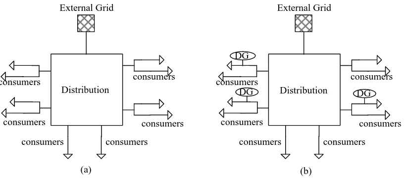
Traditionally, electrical energy in the distribution system is always supplied to the customer from upstream power resources that are connected to the bulk transmission system. A small localized power source called distributed generation (DG) becomes an alternative to bulk electric power generation due to yearly demand growth. These DGs include wind farms, micro hydro turbines, photovoltaics (PV), and other generators. These DGs are generally in the range of a few kWs up to a few MWs and have several advantages, such as environmental benefits, improved reliability, increased efficiency, prevention of transmission and distribution (T&D) capacity upgrades, improved power quality, and reduced T&D line losses (Balaguer-álvarez et al. 2010; Ray et al. 2011). Figure 1.1 shows the difference between traditional and multiple embedded distribution systems, in which additional DG is commonly connected near the local load compared with the traditional network system. Therefore, the traditional approach of energy production and distribution are changing, introducing new challenges in balancing the power system.
2
(a) (b)
Distribution External Grid
consumers consumers consumers
consumers
consumers consumers
DG DG
DG Distribution
External Grid
consumers consumers consumers
consumers
consumers consumers
Figure 1.1 (a) Traditional distribution system, (b) generation embedded distribution system
Network Load Utility
Tripped Utility Circuit Breaker
DG Industrial Site Power
Island
Local Load
Figure 1.2 Power islanding condition Sources: Ezzt et al. 2007
3
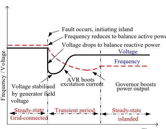
Voltage drops to balance reactive power Frequency reduces to balance active power
Transient period Steady-state islanded Steady-state
Grid-connected
Frequency Voltage
Governor boosts power output AVR boots
excitation current Voltage stabilised
by generator field voltage
Fault occurs, initiating island
Time
F
re
q
u
en
cy
/V
o
lt
ag
e
Figure 1.3 Voltage and frequency response Source: Ecconnect 2001
Generally, automatic load shedding has two types. The first type is under-frequency load shedding (UFLS), which is designed to rebalance load and generation within an electrical island once the unbalanced system is created. The second type is under-voltage load shedding (UVLS), which is utilized to prevent local area voltage collapse and to directly respond to the voltage condition in a local area. The UVLS scheme aims to shed load to restore reactive power relative to demand, to prevent voltage collapse, and to contain a voltage problem within a local area rather than allowing it to spread in geography and magnitude.
4
1.2 PROBLEM STATEMENT
Although the islanding operation has some benefits, several drawbacks are still observed, especially in unintentional islanding events. The unintentional islanding of DGs may cause problems in terms of power quality, safety, voltage and frequency stability, and interference (Mahat et al. 2011; Timbus et al. 2010). The Institute of Electrical and Electronics Engineers (IEEE) 1547-2003 standard specifies a maximum delay of 2 s for the detection of the unintentional islanding condition, whereas the IEEE 929-2000 standard requires the disconnection of the DG if islanded (Mahat et al. 2011). To achieve this goal, each DG must be capable of detecting the islanding condition as quickly as possible. Therefore, the first part of the current study attempts to develop a simple and effective method that can quickly diagnose the islanding condition by identifying the islanding and non-islanding conditions in the system.
Several techniques have been developed to accurately identify the islanding condition; the most economical and effective technique is to use a passive technique with the application of artificial intelligence (AI). This technique is preferred because a more accurate online detection is required to monitor the condition of the system. Moreover, this technique is usually less complex and has high computational efficiency with good accuracy and reliability. The most common technique being used nowadays is the combination of signal processing (SP) and neural network.