AUTOMATED SMART HANGER
MOHD SAHZRIN BIN ALIAS
This Report Is Submitted In Partial Fulfillment of Requirements for the Bachelor Degree of Electronic Engineering (Telecommunication)
Fakulti Kejuruteraan Elektronik dan Kejuruteraan Komputer Universiti Teknikal Malaysia Melaka
ii
iii
iv
v
vi
ACKNOWLEDGEMENT
vii
ABSTRACT
viii
ABSTRAK
ix
TABLE OF CONTENT
CHAPTER TITLE PAGE
TITLE i
STATUS VERIFICATION FORM ii
STUDENT DECLARATION iii
SUPERVISOR DECLARATION iv
DEDICATION v
ACKNOWLEDGEMENT vi
ABSTRACT vii
ABSTRAK viii
CONTENT ix
LIST OF FIGURES xiii
LIST OF APPENDIX xv
I INTRODUCTION 1
1.0 Background information 1
1.1 Motivation 2
1.2 Problem statement 3
1.3 Project objective 3
1.4 Scope of project 3
x
II LITERATURE REVIEW 5
2.0 Overview 6
2.1 Previous project 6
2.1.1 Automated Rainout Shelter for
Controlled Water Research 6 2.1.2 Rainfall Shelter 7-9
2.1.3 Control System Design of
Automatic Roof for Chips Drying Device (software version) 10 2.1.4 Automated Control System
For Tomato Plantation 9-11
2.2 Proteus 7 12
2.3 Multisim software 13-14
2 4 4 Channel relay module 14-15
2.5 Microcontroller Arduino UNO 15-17
2.6 DC gear motor 18
2.7 Rain sensor module 18-19
2.8 Fan and lamp 20
2.9 Power source 12V 20-21
2.10 The Arduino IDE software 21-22
III METHODOLOGY 23
3.0 Introduction 23
3.1 Process of the project 24
3.1.1 Project planning 24
3.1.2 Design. project 25 3.1.3 Coding 25
xi
3.1.5 Testing 26
3.1.6 Improvement 26
3.2 Flowchart of the project 27 3.3 Flowchart movement of the project 28
3.4 System architecture 29
3.5 Etching and drilling process 30-33
IV RESULTS AND DISCUSSIONS 34
4.0 introduction 34 4.1 Testing and output result 35
4.1.1 Hardware and prototype 35 4.1.2 Testing on breadboard 36 4.1.3 Main circuit design 37 4.1.4 Circuit automated smart hanger 37 4.1.5 Rain sensor circuit 38 4.1.6 Etching and soldering circuit 38 4.1.7 Arduino UNO connection 39 4.1.8 Connection dc gear motor 40 4.1.9 Connection all components 41
4.2 Lamp and fan 42
4.2.1 LDR sensor on sunny day 42 4.2.2 LDR sensor on dark day 43 4.2.3 Rain sensor without water 44 4.2.4 Rain sensor with water 44 4.2.5 Prototype automated smart hanger 45-47
xii
V CONCLUSION AND RECOMMENDATION 49
5.0 Introduction 49
5.1 Conclusions 50
5.2 Achievements 50
5.3 Recommendation and future upgrade 51-54
REFERENCE 55
APPENDIX A 57
APPENDIX B 58-62
xiii
LIST OF FIGURES
NO TITLE PAGE
2.1.1.1 Figure of motor drive unit 6
2.1.1.2 Figure Electrical system and weather temperature 6
2.1.2.1 Figure of structure rainfall shelter 7
2.1.1.3 Figure ofl design (prototype) for the Project 10
2.2.1Proteus software 11
2.3.1 Multisim software 12
2.3.2 Example connection by using multisim 12
2.3.1 Figure of relay 4 module 14
2.4.1 Arduino UNO as a Microcontroller 15
2.4.2 Name of every pin in Arduino UNO 15
2.5.1 DC Gear motor 17
2.6.1 Rain sensor module 18
2.6.2connection between rain sensor module and Arduino UNO 18
2.7.1Cooling fan 19
2.7.2Lamp (LED 19
2.8.1 Figure above shows Power Source 12V 19
2.9.1 Arduino software 21
2.9.2 Arduino coding 21
3.0.1 shows the designing process of this project 22
xiv
3.2.1 Flowchart to develop a project 25
3.3.1 Flowchart movement of this project 26
3.4.1 shows Architecture of System 27
3.5.1 protection layer was removed from PCB board 28
3.5.2 Placing board with PCB layout in UV machine 28
3.5.3 Supplying UV light 29
3.5.4 immersing the board in the developer liquid 29
3.5.5 Rinsing board with water 30
3.5.6 Placing board into conveyer spray processor 30
3.5.7: Drilling Process 31
4.1.1.1 Design the hardware of automated smart hanger 33 4.1.2.1 Connection between hardware and software with breadboard 33 4.1.3.1 shows the entire PCB layout design in Proteus Ares software 34
4.1.4.1 Figure show main circuit 35
4.1.5.1 shows the entire PCB layout design in Proteus Ares software 35 4.1.6.1 Figure show rain sensor circuit was etching and soldering 36 4.1.7.1 Figure show Arduino UNO connect to main circuit 36 4.1.8.1 Figure show dc gear box motor was connected to relay 37 4.1.9.1 Connection between relay module, main circuit and Arduino UNO board 38 4.2.0.1 Figure show that Lamp and Fan function when circuit running 39
4.2.1.1 above show LDR sensor testing on sunny day 39
4.2.2.1 above show LDR sensor testing on dark day 40
4.2.3.1 Figure above show that Rain sensor circuit without water 41 4.2.4.1 Figure above show that rain sensor circuit with water 41
4.2.5.1 Automated smart hanger side view 42
4.2.5.2 Automated smart hanger back view 42
4.2.5.3 Automated smart hanger front view 43
4.2.5.4 Automated smart hanger top view 43
4.2.5.5 Components automated smart hanger 44
5.3.1 Figure show improvements by using system fan dryer 48
xv
5.3.3 Figure show improvements by using system solar 49 5.3.4 Figure show motor dc controlled by potentiometer 50
LIST OF APPENDIX
NO TITLE PAGE
A Complete Prototype 53
B Full coding automated smart hanger 54
CHAPTER I
INTRODUCTION
1.0 Background Information
2
function to control component in this product. All programs and coding will be installed to Arduino UNO that will give instructions to conduct this system properly and will automatically retrieve-out the clothes when it is the sunny day and oppositely retrieve-in the clothes when it is a rainy day. In addition, this project uses DC gearbox motor to moves forward and backward so that it can move the clothes to the unexposed area. Besides that, the advantages of this product are, it can save the energy and time of other users to do the job without regard to the clothes that had dried. Moreover, these products make it easier for workers who are not at home. This product will function when raining or dark day. Then rain sensor will function as a connecting circuit. The function of DC gearbox motor in this product is to determine the motor movement rotates left or right. The time appointed will function to make the rainout shelter moves only move in a half cycle. It is intended to change the position of clothes from rain exposure. LDR sensors will be used to detect light. When the weather is dark, clothes will be moving to a place that is not exposed from rain or night.
1.1 Motivation
3
warm and nights are really cool in Malaysia. Furthermore its average climate is continually welcoming.
1.2 Problem statement
Unstable weather condition can make difficulty in drying clothes and the situation is worsen if it‟s raining. Moreover, Malaysia is located near to the equator line. This make Malaysia is prone to experience rain and damp state over the years. For people who are working, surely they worried about their clothes that left dry outside. Then, from a previous project that only can moves forward and backward to avoid clothes from rainy sometimes hang and not user friendly to uses and to fix this problem, it was upgraded by using DC gearbox motor and sensor that more comfortable for user to use. In addition, Cooling fan and light also, helped clothes make drying faster.
1.3 Project Objective
Objectives of this project are:
I. To design rain sensor circuit and LDR circuit using proteus software. II. To develop a code of controller using Arduino software.
III. To fabricate rain sensor circuit and LDR circuit.
1.4 Scope of Project
4
weather it will automatically retrieve-out the clothes when it is the sunny day and oppositely retrieve-in the clothes when it is a rainy day. The movement of this project is limited around 1meters depends to timer setting and long of suspensions.
1.5 Thesis Outline
This Automated power hanger System final thesis contains of 7 chapters and they are outlined as below:
Chapter I explains the introduction that includes concept of automatic cloth retriever system. It also outlines objective and scope of “AUTOMATED SMART HANGER”.
Chapter II describes the architecture used and gives a brief of literature review of system board architecture, sensor module, driver circuit module and output module.
Chapter III discuss on the full methodology of this project. Provides description and discussion on how the design of the hardware of each module in the systems. The module consists of microcontroller board, rain sensor, LDR sensor, DC motor, driver circuit and output devices.
Chapter IV discusses about the results and discussion explains the architecture of the project that consist the software implementation.
Chapter V discuss about the conclusion and recommendation further development of the project.
Bibliography about a journal that will be referred
CHAPTER 2
LITERATURE REVIEW
6
2.0 Overview
The first rainout shelter was built in 1962 at Iowa State University (Horton 1962). Early shelters were small in size and required trade-offs between plot size and replication of treatments as well as limiting the size of farm equipment that could be used to apply cultural practices. Since then, several designs have been developed and larger shelters have been built and were reviewed by the first rainout shelter was built in 1962 at Iowa State University (Horton 1962). Early shelters were small in size and required trade-offs between plot size and replication of treatments as well as limiting the size of farm equipment that could be used to apply cultural practices. Since then, several designs have been developed and larger shelters have been built and were reviewed by R.e ries and g.zachmeier Horton (1983) [1]. Design of this rainout shelter considered the variable and sometime severe environmental conditions experienced in the northern Great Plains. This was important since a shelter that would be durable and workable for many years was needed to justify the construction cost [2].
2.1 Previous project
2.1.1 R.e ries and g.zachmeier Horton, automated rainout shelter for controlled water re- searches. “Rainout” shelter for corn. (Iowa farm sci.)845-848. m.l 1983
7
[image:22.612.185.470.75.189.2] [image:22.612.183.469.263.354.2]
Figure 2.1.1.1: Motor drive unit
Figure 2.1.1.2: Electrical system and weather temperature
2.1.2 Arland D. Schneider, Rainfall Shelters, United States Department of Agriculture (USDA), 227–232, 2003.
8
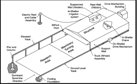
[image:23.612.117.559.76.347.2]
Figure 2.1.2.1: Structure rainfall shelter
Site
The area needs to be well drained. Overall shelter design should allow all or most of the research area to be planted, cultivated, and harvested with nice.
Tracks
Most rainfall shelters have two tracks, but some also have a center track to reduce the structure span or to support a center drive mechanism.
Structure
9
Drive Mechanism
Rainfall shelter drive mechanisms can be classified by the location and type of the drive. Rain shelter drive mechanisms are of four basic types which are cable and drum, sprocket and chain rack and pinion, and rack drive. The cable and drum mechanism is simply a closed-loop cable passing over a drive drum at the rear end of the shelter and an idler pulley at the opposite end of the tracks. A sprocket and chain drive can use either a closed-loop chain similar to the cable.
Power Supply
Alternating current (a.c.) electricity from a reliable utility grid is the preferred power supply because it allows the use of larger motors and heavier structures solar battery chargers can be used, or charged batteries can be transported to the shelter
Control System