DESIGN OF CAR WIPER SPEED CONTROLLER
MOHAMMAD ZUL AIZAM BIN MAZLAN
DESIGN OF CAR WIPER SPEED CONTROLLER
MOHAMMAD ZUL AIZAM BIN MAZLAN
This Report Is Submitted In Partial Fulfillment of Requirements for the Degree of Bachelor in Electrical Engineering
(Industrial Power)
Fakulti Kejuruteraan Elektrik
Universiti Teknikal Malaysia Melaka (UTeM)
“I hereby declared that I have read through this report and found that it has comply the partial fulfillment for awarding the degree of Bachelor of Electrical
Engineering (Power Industry)”
Signature :
Supervisor‟s Name : PROF.MADYA DR. MUSSE MOHAMUD AHMED
“I hereby declared that this report is a result of my own work except for the excerpts that have been cited clearly in the references.”
Signature :
Name : MOHAMMAD ZUL AIZAM BIN MAZLAN
ACKNOWLEDGEMENT
I wish to thank my project supervisor, Prof. Madya Dr. Musse Mohamud Ahmed for his guidance and teachings. And also would like to thank both the panels for their guidance.
I would also wish to extend my gratitude to my parents for their support and their understanding.
ABSTRACT
ABSTRAK
Objektif utama projek ini ialah untuk mereka cipta dan menghasilkan pengawal kelajuan pengelap cermin kereta. Di dalam projek ini, pengawal
pengelap cermin kereta akan dihuraikan. Ia akan menjelaskan tentang penggunaan beberapa kaedah elektronik kuasa yang dihasilkan untuk mencontohi ciri-ciri penting kepandaian manusia. Pengelap cermin kereta yang berfungsi secara berterusan telah menunjukkan ia menjadi gangguan kepada pemandu terutamanya apabila hujan tidak lebat. Dengan menggunakan litar ini, ia dapat mengelap cermin sekali dalam sesaat dan sekali dalam masa 10 saat. Di dalam projek ini, ia menggunakan dua alat pencatat masa iaitu NE555, sebuah pengira dekad
CONTENTS
CHAPTER TITLE PAGE
ACKNOWLEDGEMENTS iii
ABSTRACT iv
ABSTRAK v
LIST OF FIGURES ix
1.0 INTRODUCTION
1.1 Background 1
1.2 Problem Statement 2
1.3 Project Objective 2
1.4 Project Scope 2
1.5 Methodology 3
2.0 LITERATURE REVIEW
2.1 Introduction 5
2.2 Integrated Circuit (IC) 6
2.3 NE 555 (timer) 7
2.3.2 Pin Functions - 8 pin package 8 2.3.3 NE555 timer in astable operation 9
2.3.4 NE555 in monostable state 11
2.4 CD4017 Decade Counter 13
2.4.1 Features 13
2.4.2 Applications 13
2.5 TIP 32 (driver transistor) 17
2.6 TIP 3055 (power transistor) 18
2.7 Software part 19
2.7.1 Proteus professional 7 19 3.0 METHODOLOGY
3.1 Methodology of the project 21
3.2 Hardware design 22
3.2.1 Monostable multivibrator design 23
3.2.2 Decade counter design 25
3.2.3 Astable multivibrator 26
3.3 Hardware development process 28
3.4 Project planning schedule (Gantt chart) 29 4.0 HARDWARE VERIFICATION AND EXPERIMENTAL RESULTS
4.1 Results Achievement 30
4.3 Hardware verification 31 4.3.1 Power supply (car battery 12v) 31 4.3.2 Monostable multivibrator (NE 555) 32
4.3.3 Decade counter (CD 4017) 32
4.3.4 Astable multivibrator (NE 555) 33
4.3.5 Wiper motor driver 33
4.4 Experimental results 34
4.4.1 Power supply 34
4.4.2 Transistor 35
4.4.3 Waveform 36
4.5 The ability of the hardware 36
5.0 DISCUSSION 37
6.0 CONCLUSION AND RECOMMENDATION
6.1 Conclusion 39
6.2 Recommendation 40
7.0 REFERENCES 41
LIST OF FIGURES FIGURE TITLE
PAGE
1.0 The block diagram of the circuit operation 3
1.1 Project flow chart 4
2.0 Pin Connection (top view) 8
2.1 Astable operation 10
2.2 Monostable operation 11
2.3 Monostable circuit 12
2.4(a) CD4017 Connection Diagram 14
2.4(b) Timing Diagram 15
2.4(c) Logic Diagram 16
2.5(a) TIP 32 configuration 17
2.5(b) Internal schematic diagram 17
2.6 TIP 3055 configuration 18
2.7 The proteus professional 7 software 19
3.0 The block diagram of the circuit operation 20
3.2 Circuit diagram for wiper speed controller 23 3.3 Monostable input and ouput waveform 23
3.4 Monostable design 24
3.5(a) Decade counter design 25
3.5(b) Variable resistor connected to CD 4017 25 3.6(a) Astable input and output waveform 27
3.6(b) Astable design 27
3.7 Hardware development process 28
3.8 Gantt chart schedule 29
4.0 Car battery 12v 31
4.1 Monostable multivibrator development 32
4.2 Decade counter development 32
4.3 Astable multivibrator development 33
4.4 Wiper motor driver development 33
4.5 DC motor 12v 33
4.6 12v battery testing 34
4.7(a) TIP 3055 testing 35
4.7(b) TIP 32 testing 35
4.8 Monostable 36
4.9 Astable 36
CHAPTER 1.0
INTRODUCTION
1.6 Background
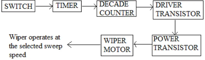
A continuously working wiper in a car may prove to be nuisance, especially when it is not raining heavily. By using the circuit described here one can vary sweeping rate or the wiper from once a second to once in ten seconds. The circuit comprises two timers NE555 ICs‟, one CD4017 decade counter, one TIP32 driver transistor, a 2N3055 power transistor (or TIP3055) and a few other discrete components. Timer IC1 is configured as a monostable multivibrator which produces a pulse when one presses of switch S1 momentarily. This pulse acts as a clock pulse for the decade counter (IC2) which advances by one count on each successive clock pulse or the push of switch S1. Ten preset (VR1 through VR10), set for different values by trial and error are used at the ten outputs of the IC2. But since only one output of IC2 is high at a time, only one preset (at selected output) effectively come in series with the timing resistors R4 and R5 connected in the circuit of timer IC3 which functions in astable mode. As presets VR1 through VR10 are set for different values, different time periods (or frequencies) for astable multivibrator IC3 can be selected. The output of IC3 is applied to PNP driver transistor T1 (TIP32) for driving the final power transistor T2 (2N3055) which in turn drives the wiper motor at the selected sweep speed.
this project are timer, decade counter, driver transistor, power transistor and wiper motor.
1.7 Problem Statement
Nowadays, a working wiper in a vehicle may prove to be nuisance, especially when it is not raining heavily. At low speeds, rainfalls on the window at high rate reducing visibility greatly and necessitating the use of the wiper. As speed increases, less water stays on the window, making an intermittent function desirable. At high speeds, almost no water gets on the window. In this project, a pre-set control circuit (VR1-VR10)will be used to increase and decrease the desired speed of the wiper. Otherwise, the driver can select different time periods (or frequencies) which in turn drives the wiper motor at the selected sweep speed.
1.8 Project Objective
To design and develop an intelligent wiper speed controller. To make the controller operate at the selected sweep speed. To increase the driver‟s visibility when it is not raining heavily. To build and upgrade the function of the basic wiper speed
controller.
1.9 Project Scope
To understand the basic operation of the circuit. To design and testing the circuit.
To make full report.
1.10 Methodology
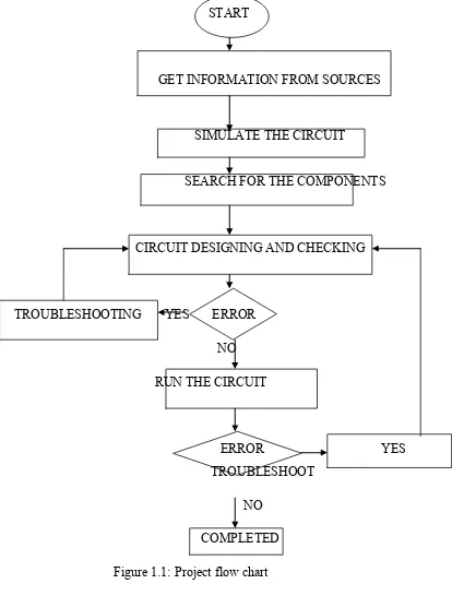
[image:15.612.160.488.294.391.2]The block diagram of the system is shown in Figure 1.0 below:
START
GET INFORMATION FROM SOURCES
SIMULATE THE CIRCUIT
SEARCH FOR THE COMPONENTS
CIRCUIT DESIGNING AND CHECKING
TROUBLESHOOTING YES ERROR NO RUN THE CIRCUIT
ERROR YES TROUBLESHOOT
NO
[image:16.612.131.545.67.613.2]CHAPTER 2.0
LITERATURE REVIEW
2.4 Introduction
In electronics, an integrated circuit (also known as IC,
microcircuit, microchip, silicon chip, or chip) is a miniaturized electronic circuit (consisting mainly of semoconductor devices, as well as passive components) which are manufactured in the surface of a thin substrate of semiconductor material. Integrated circuits are used in almost all
electronic equipment in use today and have revolutionized the world of electronics. A hybrid integrated circuit is a miniaturized electronic circuit constructed of individual semiconductor devices, as well as passive components, bonded to a substrate or circuit board. [6]
Integrated circuits were made possible by experimental discoveries which showed that semiconductor devices could perform the functions of vacuum tubes, and by mid-20th-century technology advancements in semiconductor device fabrication. The integration of large numbers of tiny transistors into a small chip was an enormous improvement over the manual assembly of circuits using discrete electronic components. The integrated circuit mass production capability, reliability, and building-block approach to circuit design ensured the rapid adoption of
2.5 Integrated Circuit (IC) [6]
There are two main advantages of ICs over discrete circuits:
cost
performance
Cost is low because the chips, with all their components, are printed as a unit by photolithography and not constructed one transistor at a time. Furthermore, much less material is used to construct a circuit as a packaged IC die than as a discrete circuit. Performance is high since the components switch quickly and consume little power (compared to their discrete counterparts), because the components are small and close together. As of 2006, chip areas range from a few square mm to around 350 mm², with up to 1 million transistors per mm².
Among the most advanced integrated circuits are the
This increased capacity per unit area can be used to decrease cost and/or increase functionality.
2.6 NE 555 (timer) [10]
The NE555 monolithic timing circuit is a highly stable controller capable of producing accurate time delays or oscillation. In the time delay mode of operation, the time is precisely controlled by one external resistor and capacitor. For astable operation as an oscillator, the free running frequency and the duty cycle are both accurately controlled with two external resistors and one capacitor. The circuit may be triggered and reset on falling waveforms, and the output structure can source or sink up to 200mA. The NE555 is available in plastic and ceramic minidip package and in a 8-leadmicropackage and inmetal can package version.
The 555 timer is an extremely versatile integrated circuit which can be used to build lots of different circuits. You can use the 555 effectively without understanding the function of each pin in detail.
Frequently, the 555 is used in astable mode to generate a
continuous series of pulses, but you can also use the 555 to make a one-shot or monostable circuit. The 555 can source or sink 200 mA of output current, and is capable of driving wide range of output devices.
2.3.1 Timer NE555 Features
Low turn off time
Maximum operating frequency greater than 500kHz Timing from microseconds to hours
High output current can source or sink 200mA Adjustable duty cycle
TTL Compatible
[image:20.612.124.488.218.437.2] Temperature stability of 0.005% per 0C
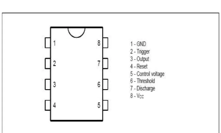
Figure 2.0: Pin Connection (top view)
2.3.2 Pin Functions - 8 pin package
-Ground (Pin 1)
This pin is connected directly to ground.
This pin is the input to the lower comparator and is used to set the latch, which in turn causes the output to go high.
-Output (Pin 3)
Output high is about 1.7V less than supply. Output low is capable of Isink up to 200mA.
-Reset (Pin 4)
This is used to reset the latch and return the output to a low state. The reset is an overriding function and when not used connect to V+.
-Control (Pin 5)
Allows access to the 2/3V+ voltage divider point when the 555 timer is used in voltage control mode. When not used it is
connected to ground through a 0.01 uF capacitor.
-Threshold (Pin 6)
This is an input to the upper comparator. See data sheet for comprehensive explanation.
-Discharge (Pin 7)
This is the open collector of a NPN transistor.
-V+ (Pin 8)
version is 3V - 16V DC. Note comments about effective supply filtering and bypassing this pin below under "General
considerations by using a 555 timer".
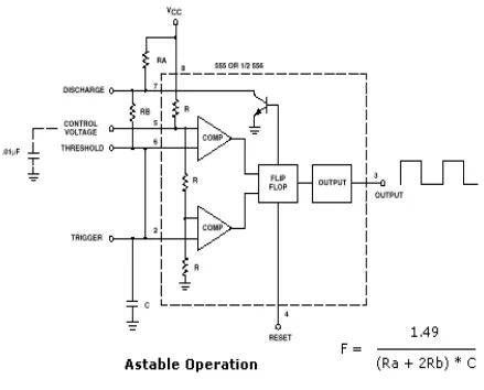
2.3.5 NE555 timer in astable operation
When configured as an oscillator, the 555 timer is configured as in figure 2.1 below. This is the free running mode and the trigger is tied to the threshold pin. At power-up, the capacitor is discharged, holding the trigger low. This triggers the timer, which establishes the capacitor charge path through Ra and Rb. When the capacitor reaches the threshold level of 2/3 Vcc, the output drops low and the discharge transistor turns on. The timing capacitor now discharges through Rb.
When the capacitor voltage drops to 1/3 Vcc, the trigger comparator trips, automatically retriggering the timer, creating an
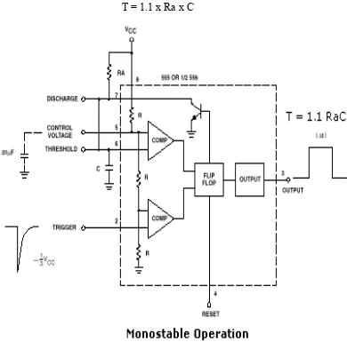
2.3.6 NE555 in monostable state
Another popular application for the 555 timer is the monostable mode (one shot) which requires only two external components, Ra and C in figure 2.2 below. Time period is determined by
[image:24.612.154.544.154.539.2]T = 1.1 x Ra x C