I admit that I have read this report and in my opinion this report is sufficient from the perspective of the scope and quality for award.ing purposes Bachelor of Mechanical Engineering (Thermal Fluid)
Signature
TO IDENTIFY ON THERMODYNAMIC STEAM TRAP F AlLURE MECHANISM ON HORIZONTAL INSTALLATION.
MOHD NOR HAKIM BlN MOHD TAffi
This report project is submitted to Faculty of Mechanical Engineering
In partial fulfillment for
Bachelor of Mechanical Engineering (lbermal Fluid)
Faculty of Mechanical Engineering Kolej Universiti Teknikal Kebangsaan Malaysia
I hereby declare that the word or the sentences in this thesis is of my own except for quotations and summarize which have been acknowledge.
Signature Writer Name Date
: ..
}.5!:::. ...
... .
: Mohd Nor Hakim bin Mohd Taib
: /l.f
I> J sセjNエャGエ@ .).(n !"Ill
ACKNOWLEDGEMENT
ln the name of Allah, The Most Gracious, The Most Merciful. First and foremost, I thank to Allah for giving me the opportunity to complete my thesis successfully.
I would like to take this opportunity to express my deepest gratitude towards Faculty of Mechanical Engineering, Kolej Universiti Teknikal Kebangsaan Malaysia (KUTKM) and Petronas Penapisan Melaka Sdn. Bhd. (PPMSB) for giving me the guidance and chance to finish my thesis. Special thanks to Faculty of Mechanical Engineering Dean, Professor Dr Md Razali b Ayub for his concern and guidance over student thesis
and
Mr. Mohd lzzat b Mohd Khazar, Mechanical Engineer, Operational Performance Improvement Unit in PPMSB for his consistent supervision, guidance, support and encouragement throughout this project
and
Mr Yusmady b Mohamed Arifin, my KUTK.M supervisor who had given his full commitment and support towards the project
iv
ABSTRACT
v
ABSTRAK
VI
LIST OF CONTENT
CHAPTER TITLE PAGE
I INTRODUCTION 1
1.1 Introduction ofProject
1.2
Purpose of the Study2
1.3
Problem Statement2
1.4
Focus3
1.5 Objectives 3
1.6
Scope3
1.7 Outline Thesis
4
2 LITERATURE REVIEW 5
2.1
Introduction of Steam System 52.2
Types of Steam6
2.3
Steam System Operation7
2.4
The Need for Steam Trap in Steam System 102.5
The Classification of Steam Trap12
2.6
Operating Conditions of Steam Trap19
vii
3 METHODOLOGY
26
3.1
Steam Trap Test Equipment26
3.2
Test Preparation27
3.3
Flow Chart of Methodology28
4
RESULTS AND DISCUSSIONS29
4.1
Definition of Critical Point29
4.2
Actual Sample of Steam Trap31
4.3
Steam Trap Modeling36
4.4
Simulation Result of Steam Trap for Open Disc37
4.5
Simulation Result of Steam Trap for Close Disc43
5 CONCLUSION AND RECOMMENDATIONS
50
6 REFERENCES
53
USTOFTABLE
TABLE NO. TITLE
1-1 Types of Steam
2-1 Different Trap Types and Their Classifications
PAGE
7
18
IX
UST OF FIGURE
FIGURE NO TITLE PAGE
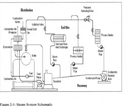
2-1 Steam System Schematic 10
2-2 Inverted Bucket Steam Trap 13
2-3 Bimetallic Steam Trap 14
2-4 Bellows Steam Trap 15
2-5 Float and Thermostatic Steam Trap 16
2-6 Disc Steam Trap 17
2-7 Common Steam Trap Arrangement 20
4-1 Internal View of Thermodynamic Steam Trap 30 4-2 Actual Sample ofThennodynamic Steam Trap
.
(Side View) 31
4-3 Top View of Actual Steam Trap in
Good Condition 34
4-4 Top View of Actual Steam Trap in
Bad Condition ( 1 ). 35
4-5 Top View of Actual Steam Trap in
Bad Condition (2). 35
4-6 Steam Trap Sample
(Assembly of Body, Cap and Strainer Cap) 36 4-7 Side View of Simulation Sample
(Disc Open) for Velocity 37
4-8 Isometric View of Simulation Sample
X
4-9
Side View of Simulation Sample(Disc Open) for Pressure
39
4-10
Isometric View of Simulation Sample(Disc Open) for Pressure
40
4-11
Isometric View of Critical Point in Steam Trap(Disc Open)
41
4-12
Side View of Critical Point in Steam Trap(Disc Open)
42
4-13
Side View of Simulation Sample(Disc Close) for Velocity
43
4-14
Isometric View of Simu.lation Sample(Disc Close) for Velocity 44
4-15
Side View of Simulation Sample(Disc Close) for Pressure
45
4-16
Isometric View of Simu.lation Sample(Disc Close) for Pressure
46
4-17
Isometric View of Critical Point in Steam Trap(Disc Close)
47
4-18
Side View of Critical Point in Steam TrapNOMENCLATURE HP MP
LP
LLP
PERMATA CFDOK
FO FC FOP OS OFF UNK N/A PPMSBLIST OF NOMENCLATURE
DEFINITION High Pressure
Medium Pressure Low Pressure Low Low Pressure
Petronas Management Training Computational Fluid Dynamic Normally Operating
Failed Open Failed Close Failed Open Partial Out of Service Off
Unknown Not Accessible
Petronas Penapisan Melaka Sdn Bhd
APPENDICES
A
B
c
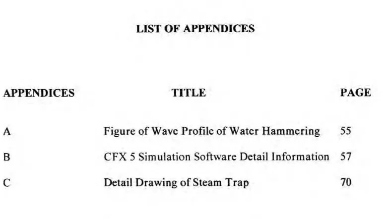
LIST OF APPENDICES
[image:13.543.88.478.92.313.2]TITLE PAGE
Figure of Wave Profile of Water Hammering 55
CFX 5 Simulation Software Detail Information 57
Detail Drawing of Steam Trap 70
CHAPTER!
INTRODUCTION
1.1 Introduction of Project
Condensate is formed whenever steam gives up its enthalpy of evaporation (latent heat). The proper removal of condensate from steam plant of all types is vitaJ if the plant is to work efficiently and this operation is commonly performed by a steam trap.
Frequent causes bf unsatisfactory condensate drainage include the choice of the wrong type of steam trap for the application, the use of a trap that is incorrectly sized for the load and pressure conditions and bad installation. Because any of these factors can seriously reduce plant output, it is worth spending some time studying how steam traps work and their application.
A steam trap is a self-contained automatic valve which automatically drains the condensate from a steam-containing enclosure while remaining closed to live steam. Some traps pass live steam at a controlled rate. Most traps also pass air and other non condensate gases while remaining closed to live steam.
2
Efforts and methods implementation needs to be considered are; study on the steam trap characteristics, design and how it works in real application in industry. The methodology uses are theoretical and simulation. The role of theoretical method in this study is to get the beginning data of steam system used in industry, frequent used of steam trap in industry and also type of failure happen on steam trap in industry. Meanwhile, the simulation method is to see the change and to compare result with theoretical method. The type of simulation use is CFX-5 to get the beginning result.
1.2 Purpose of the Study
The purpose of this study is to learn how the internal parts of thermodynamic steam trap fail. CFX-5 simulation software is used in order to implement the task. Steam trap internal part needed to be emphasis with perfect sizing to investigate the part that gives an effect on steam trap efficiency.
1.3 Problem Statement
3
1.4 Focus
The focus of this study is at the internal part of thermodynamic steam trap. The component need to be emphasis is when steam flow into inlet of thermodynamic steam trap and moving around the steam trap, critical point of steam trap should be
analyzed in order to increase its efficiency.
1.5 Objectives
The objectives of this study are as follows:
l. To learn how the steam traps functioning and operate in steam system. 2. To learn how the internal parts of thermodynamic steam trap fail
3. To compare the failure of actual sample and simulation sample of steam trap 4. To find a solution how to overcome the failure of steam trap.
In order to comJllete the task, need to study on thermodynamic steam trap internal part and doing simulation by using CFX-5 Simulation Software. It is intended to know the involved basic principle such as principle of steam trap, how it works and early study on steam system used in industry.
1.6 Scope
4
Computational Fluid Dynamic (CFD). In addition, we have to find a solution how to overcome this failure by doing the analysis and give a suitable recommendation.
1. 7 Outline Thesis
In chapter 2, it is explained about the literature review that has been done. There are many title of thesis by earlier researcher on how to improve the performance of steam trap. Within this research, there are many factors that influence the steam trap efficiency such as quality of steam used, maintenance of steam trap and type of steam trap used in industry.
In chapter 3, this part explains about method used in order to solve the problem that involve in this research. Simulator program is used to get the result on the experiment. The type of simulator used is CFX-5. Meanwhile, steam trap used is thermodynamic steam trap and the research is on the internal part of thermodynamic steam trap. It also expla.ins about expected resuJt that can be achieved. The result possibility is the critical point in internal part of steam trap when steam is flowing through it can be found.
[n chapter 4, the result and discussion of overaU simulation will be explained in full detail about the main founding during simulation.
5
CHAPTER2
LITERATURE REVIEW
2.1 Introduction of Steam System
There are three principal fonns of energy used in industrial processes: electricity, direct-fired heat, and steam. Electricity is used in many different ways, including mechanical drive, heating, and electrochemical reactions. Direct-frred energy directly transfers the heat of fuel combustion to a process. Steam provides process heating, pressure control, mechanical drive, component separation, and is a source of water for many, process reactions.
Steam has many performance advantages that make it an indispensable means of delivering energy. These advantages include low toxicity, ease of transportability, high efficiency, high heat capacity, and low cost with respect to the other alternatives. Steam holds a significant amount of energy on a unit mass basis (between 1,000 and 1,250 Btu/lb) that can be extracted as mechanical work through a turbine or as heat for process use. Since most ofthe heat content of steam is stored as latent heat, large quantities of heat can be transferred efficiently at a constant temperature, which is a useful attribute in many process heating applications.
6
control the pressures and temperatures of many chemical processes. Other significant applications of steam are to strip contaminants from a process fluid, to facilitate the fractionation of hydrocarbon components, and to dry all types of paper products. (Bioom.D. et al, 2001),
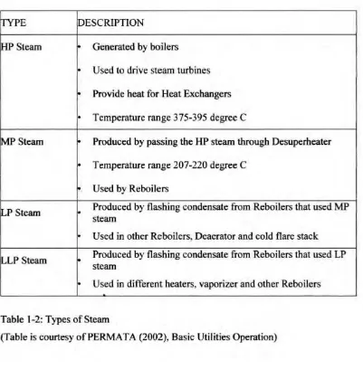
2.2 Types of Steam
There are four types of steam systems: 1. High Pressure Steam (HP)
7
[TYPE DESCRIPTION
セsエ・。ュ@ • Generated by boilers
Used to drive steam turbines • Provide heat for Heat Exchangers • Temperature range 375-395 degree C
IMP
Steam • Produced by passing the HP steam through Desuperheater• Temperature range 207-220 degree C • Used by Reboilers
ILP Steam
.
Produced by flashing condensate from Reboilers that used MP steamUsed in other Reboilers, Deaerator and cold flare stack セlp@ Steam • Produced by flashing condensate from Reboilers that used LP
steam
• Used in different heaters, vaporizer and other Reboilers
Table l-2: Types of Steam
(Table is courtesy ofPERMA TA (2002), Basic Utilities Operation)
2.3 Steam System Operation
[image:20.543.93.494.64.483.2]8
2.3.1 Generation
Steam is generated in a boiler or a heat recovery steam generator by transferring the heat of combustion gases to water. When water absorbs enough heat, it changes phase from liquid to steam. [n some boilers; a superheater further increases the energy content of the steam. Under pressure, the steam then flows from the boiler or steam generator and into the distribution system. (Bloom D. et al, 2001)
2.3.2 Distribution
The distribution system carries steam from the boiler or generator to the points of end use. Many distribution systems have several take-off lines that operate at different pressures. These distribution lines are separated by various types of isolation valves, pressure regulating valves, and, sometimes, backpressure turbines.
A properly performing distribution system delivers sufficient quantities of high quality steam at the right pressures and temperatures to the end uses. Effective distribution system performance requires proper steam pressure balance, good condensate drainage, adequate insulation, and effective pressure regulation. (Bloom D. et al, 2001)
2.3.3 End Use
9
which point the trap passes the condensate into the condensate return system. In a turbine, the steam transforms its energy to mechanical work to drive rotating machinery such as pumps, compressors, or electric generators. In fractionating towers, steam facilitates the separation of various components of a process fluid. In stripping applications, the steam pulls contaminants out of a process fluid. Steam is also used as a source of water for certain chemical reactions. In steam methane reforming, steam is a source of hydrogen. (Bloom D. et al, 2001)
2.3.4 Recovery
Distribution
End
Use
Stm Trap
Cont u::W II ) II
[image:23.543.94.506.42.383.2]Recovery
Figure 2-1: Steam System Schematic
I
(TIIustration Courtesy of Bloom D. et al, 200 I)
2.4 The Need for Steam Trap in Steam System
Stm Tnp
10
Humankind has developed an almost insatiable thirst for energy especially the demand for fossilized fuel s that can be burned in boilers to produce heat and then indirectly power.
11
Steam is generated in the boiler and conveyed through piping to the steam
using equipment. However in spite of the fact that the steam pipe work is usuall y
well insulated to prevent the loss of heat, some heat will be radiated from the piping.
Steam traveling along the pipe work will transfer some of the heat is carrying to the
wall of the pipe to make up the losses due to radiation and in so doing some of the
system will condense forming condensate (hot water) in the bottom of the pipe.
If this condensate were allowed to remain in the pipe, it would both extract
more heat from the steam and also gradually fill up the pipe, blocking the passage of
steam with disastrous consequences. What is therefore required is a simple automatic
device that will allow such condensate to drain from the pipe without allowing steam
to escape.
Such a device is known as a steam trap and its importance in maintaining the
safety and efficiency of the steam system should not be underestimated. Similarly
when steam finally enters the equipments, heat is transferred through the wall to the
fluid or product being ィセ。エ・、N@ As the steam is gives up its heat it condenses, the condensate so formed beginning to collect within the steam space of the equipment.
Like the steam pipe work, this condensate should not be allowed to remain,
otherwise the process of heat transfer would slow down and eventually cease
altogether.
Once again, therefore, the simple automatic steam trap must be used to drain away the condensate without any steam escaping. Steam traps are however required
to carry out one further function that is not at first apparent. When a steam system is
shut down air enters the pipe work to occupy the space left by the condensing steam.
Upon start up this air is pushed ahead of the steam to the far point of the pipe work
system and also into the steam using equipment. It therefore reaches the drain outlets
to which the steam traps are connected. Steam trap must also then be capable of