UNIVERSITI TEKNIKAL MALAYSIA MELAKA
FACULTY OF ELECTRICAL ENGINEERING
BEKU 4894
FINAL YEAR PROJECT
REPORT
DYNAMIC MODELING OF A DOUBLE-PENDULUM GANTRY CRANE
SYSTEM
NAME : NOOR FATIHA BINTI OMAR
COURSE : 4 BEKC
SESSION : 2013/2014
MATRIX NO : B011110149
LECTURER’S NAME : EN. HAZRIQ IZZUAN BIN JAAFAR
DYNAMIC MODELING OF A DOUBLE-PENDULUM GANTRY CRANE SYSTEM
NOOR FATIHA BINTI OMAR
A report submitted in partial fulfillment of the requirements for the degree of Bachelor of Electrical Engineering (Control, Instrumentation and Automation)
Faculty of Electrical Engineering
UNIVERSITI TEKNIKAL MALAYSIA MELAKA
iv
v
ACKNOWLEDGEMENT
Firstly, I would like to express my gratitude and appreciation to all those who gave me the possibility to complete this report. Deepest thanks to my supervisor, Encik Hazriq Izzuan Bin Jaafar for his invaluable guidance, stimulating suggestions and encouragement to complete this project. During under his supervision, lot of valuable information is obtained in order to coordinate and complete this project and thesis in the time given.
Special thanks and higher appreciation to my parents, family and special mate of mine for their cooperation, constructive suggestion and also supports from the beginning until the ends during the period of the project. Also thanks to all of my friends and others, that has been contributed by supporting and helps myself during the final year project progress till it is fully completed.
vi
ABSTRACT
vii
ABSTRAK
viii
ix 3.3 Bang-bang Input Solution 17
4 MODELING OF A DOUBLE-PENDULUM
GANTRY CRANE SYSTEM (DPGCS)
4.0 Overview 18
4.1 Model of DPGCS 18 4.2 Mathematical Modeling of DPGCS 21
5 RESULTS, ANALYSIS AND DISCUSSIONS
5.0 Overview 34
5.1 Simulation Model of DPGCS 34 5.2 First Phase: Analysis of DPGCS Behavior 36 5.2.1 Different Payload Mass (m2) 37
5.3 Second Phase: Analysis of DPGCS Behavior
with Various Parameters Setting 42 5.3.1 Different Input Force (N) 43 5.3.2 Different Hook Length (L1) 49
5.3.3 Different Load Length (L2) 54
5.3.4 Different Hook Mass (m1) 59
5.3.5 Different Trolley Mass (m3) 64
5.4 Result and Analysis 71
6 CONCLUSION AND RECOMMENDATION
6.0 Overview 77 6.1 Conclusion 77
6.11 Conclusion of First Phase: Analysis of
x
6.12 Conclusion of Second Phase: Analysis of DPGCS Behavior with Various
Parameters Setting 78 6.2 Recommendation 78
REFERENCES 80
APPENDIX A 84
APPENDIX B 86
xi
LIST OF TABLES
NO TITLE PAGE
2.1 Summary for the type of technique use in years
(2013-1998) 12 2.2 Research of dynamic modeling (2013-2009) 13 4.1 Parameter of the DPGCS 20 4.2 The system’s variable 20 5.1 Trolley Displacement with different Payload Mass (m2) 38 5.2 Hook Swing Angle with Different Payload Mass (m2) 39 5.3 Load Swing Angle with Different Payload Mass (m2) 40 5.4 Trolley Displacement with Input Force (N) 46 5.5 Hook Swing Angle with different Input Force (N) 47 5.6 Payload Swing Angle with different Input Force (N) 48 5.7 Trolley Displacement with different Hook Length (L1) 51 5.8 Hook Swing Angle with different Hook Length (L1) 52 5.9 Payload Swing Angle with different Hook Length (L1) 53 5.10 Trolley Displacement with different Load Length (L2) 56 5.11 Hook Swing Angle with different Load Length (L2) 57 5.12 Payload Swing Angle with different Load Length (L2) 58 5.13 Trolley Displacement with different Hook Mass (m1) 61 5.14 Hook Swing Angle with different Hook Mass (m1) 62 5.15 Payload Swing Angle with different Hook Mass (m1) 63 5.16 Trolley Displacement with different Trolley Mass (m3) 66 5.17 Hook Swing Angle with different Trolley Mass (m3) 67 5.18 Payload Swing Angle with different Trolley Mass (m3) 68
5.19 Behavior of Double Pendulum Gantry Crane Model
xiii
LIST OF FIGURES
NO TITLE PAGE
1.1 Industrial Gantry Crane System (GCS) 2 1.2 The overview of the crane accident 4 3.1 Flow Chart for the methodology of the Project 15 3.2 Bang-bang Input Force 17 4.1 Description of the DPGCS 19 4.2 Position Analysis of DPGCS 22 4.3 Velocity Analysis 24 4.4 Simplify of Velocity Analysis 25 4.5 Velocity Analysis for V1 26
4.6 Velocity Analysis for V2 26
5.1 Simulink of DPGCS 35 5.2 Block Diagram inside the DPGCS Model 35 5.3 List of Parameters 36 5.4 Different Payload Mass Setting,
(a) 1 kg (b) 5 kg (c) 10 kg 37 5.5 Bang-bang Input (5 N) for Different Payload Mass 38 5.6 Response of Trolley Displacement with Different
Payload Mass (m2) 39 5.7 Response of Hook Swing Angle with Different
Payload Mass (m2) 40 5.8 Response of Payload Swing Angle with Different
Payload Mass (m2) 41 5.9 Simulink of DPGCS with Various Parameters Setting 42 5.10 Different Input Force Setting
xiv
5.13 Bang-bang Input (10 N) for Different Payload Mass 45 5.14 Response of Trolley Displacement with Different
Input Force (N) 46 5.15 Response of Hook Swing Angle with Different
Input Force (N) 47 5.16 Response of Payload Swing Angle with Different
Input Force (N) 48 5.17 Different Hook Length Setting
(1.15 m, 1.55 m & 2.00 m) 49 5.18 Bang-bang Input (5 N) for Different Hook Length 50 5.19 Response of Trolley Displacement with Different
Hook Oscillation (L1) 51 5.20 Response of Hook Swing Angle with Different
Hook Oscillation (L1) 52 5.21 Response of Payload Swing Angle with Different
Hook Oscillation (L1) 53 5.22 Different Load Length Setting
(0.15 m, 0.55 m & 1.00 m) 54 5.23 Bang-bang Input (5 N) for Different Load Length 55 5.24 Response of Trolley Displacement with Different
Load Length (L2) 56 5.25 Response of Hook Swing Angle with Different
Load Length (L2) 57 5.26 Response of Payload Swing Angle with Different
Load Length (L2) 58 5.27 Different Hook Mass Setting (1 kg, 5 kg & 10 kg) 59 5.28 Bang-bang Input (5 N) for Different Hook Mass 60 5.29 Response of Trolley Displacement with Different
Hook Mass (m1) 61 5.30 Response of Hook Swing Angle with Different
Hook Mass (m1) 62 5.31 Response of Payload Swing Angle with Different
xv
5.33 Bang-bang Input (5 N) for Different Trolley Mass 65 5.34 Response of Trolley Displacement with Different
Trolley Mass (m3) 66 5.35 Response of Hook Swing Angle with Different
Trolley Mass (m3) 67 5.36 Response of Payload Swing Angle Swing Angle with
Different Trolley Mass (m3) 68 5.37 Different Input Force (N) 71 5.30 Different Hook Length (L1) 72 5.31 Different Load Length (L2) 73 5.32 Different Hook Mass (m1) 74 5.33 Different Payload Mass (m2) 75 5.34 Different Trolley Mass (m3) 76
xvi
LIST OF ABBREVIATIONS
DPGCS - Double-Pendulum Gantry Crane System
xvii
LIST OF SYMBOLS
m1 - Hook Mass
m2 - Payload Mass
m3 - Trolley Mass
L1 - Hook Pendulum Length
L2 - Load Pendulum Length
g - Gravity Acceleration
F - Bang-bang Force Input
x (m) - Trolley Displacement
θ1 - Hook Swing Angle
θ2 - Load Swing Angle
kg - Kilogram (Mass unit)
N - Newton (Force unit)
xviii
LIST OF APPENDICES
APPENDIX TITLE PAGE
A Gantt chart for Final Year Project 1
(BEKU 4792) 84
B Gantt chart for Final Year Project 2
(BEKU 4894) 86
1
CHAPTER 1
INTRODUCTION
1.0 Overview
This chapter will be discussed about the Gantry Crane System (GCS) dynamic analysis. The project objective, problem statement, scopes of work and methodology will also be presented in this chapter.
1.1 Gantry Crane System
2
the appropriate training to control the crane with more secure. The operator have the responsibility to plan carefully and taken the inspection before controlling the crane.
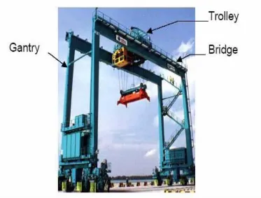
Thus, GCS supports to hold the load at a fixed location to move left or right and high or low. It consists of two or more legs parallel to each other on the bridge as shown in Figure 1.1. The heights of loads are depending on the maximum hook height. Samson and the Goliath have built the largest GCS ever that could each lift up to 840 tons [16].
Figure 1.1: Industrial Gantry Crane System (GCS)
3
crane behaves like a single-pendulum, the crane operators can eliminate much of the residual motion by causing a deceleration oscillation that cancel the oscillation induced during acceleration. For the system that behaves like a double pendulum, manual method of eliminating residual vibration becomes very difficult even for the most experienced operators. It may cause an accident if the problem cannot be resolved.
1.2 Motivation
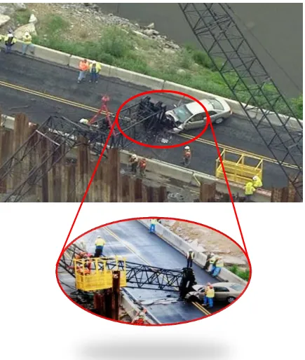
Safety issues are very important because the GCS involved the use of shipping heavy loads. Gantry crane accidents have the potential to cause a serious injury or death to employees and other person involved. Many cases have been reported involving an accident on the gantry crane. This accident occurred is due to failure in handling the crane and may cause load collapse. Even though the person that have been injured in accidents have the legal right to claim compensation for the losses if cause by the negligence of the employer but precaution is better to avoid the injury occurred.
This matter can be supported with incident occurred involving crane which is on May 21, 2013 (Tuesday) at the Gallatin, Tennessee where the crane (Terex/American 165) owned and operated by Mountain States Contractors. According to the inspection report, a construction worker died on previous works. During the incident happen, the crane was collapse and fall on to a moving car. In this accident, nobody was seriously hurt on Highway 109 in Gallatin when the crane was crashed down the car. Gallatin police reported that the strong winds at that time in the afternoon were caused of the accident.
4
5
1.3 Problem Statement
i. Gantry crane has been developed to transfer heavy load as fast as possible or in a short period of time without causing any excessive swing at the desired position. However, the trolley acceleration always induces unwanted load swing. If the mass of trolley were increased, swing angle becomes larger. It requires more time to minimize the swing angle.
ii. Most of the gantry crane is manually controlled by the skillful and experience operators in handling cranes in order to make sure the payload stop swaying at correct position. A manual control is one of the factors that cause an accident in case of carelessness in handling the cranes. If the load becomes larger, it may cause accident and also harm people surrounding.
1.4 Significant of Project
i. According to previous researches, a lot of controllers have been designed in order to find the good performance of DPGCS. Most of controllers are used to control the trolley position and payload oscillation. However, the expected result still cannot be solved.