i
SWAY REDUCTION ON GANTRY CRANE SYSTEM USING DELAYED FEEDBACK SIGNAL (DFS)
NORASHID BIN IDRUS
This report is submitted in partial fulfillment of the requirements for the award of Bachelor of Electronic Engineering (Industrial Electronics) With Honours
Faculty of Electronic and Computer Engineering Universiti Teknikal Malaysia Melaka
ii
UNIVERSTI TEKNIKAL MALAYSIA MELAKA
FAKULTI KEJURUTERAAN ELEKTRONIK DAN KEJURUTERAAN KOMPUTER
BORANG PENGESAHAN STATUS LAPORAN PROJEK SARJANA MUDA II
Tajuk Projek :
Sesi Pengajian :
Saya NORASHID BIN IDRUS
mengaku membenarkan Laporan Projek Sarjana Muda ini disimpan di Perpustakaan dengan syarat-syarat kegunaan seperti berikut:
1. Laporan adalah hakmilik Universiti Teknikal Malaysia Melaka.
2. Perpustakaan dibenarkan membuat salinan untuk tujuan pengajian sahaja.
3. Perpustakaan dibenarkan membuat salinan laporan ini sebagai bahan pertukaran antara institusi pengajian tinggi.
4. Sila tandakan ( √ ) :
SULIT*
(Mengandungi maklumat yang berdarjah keselamatan atau kepentingan Malaysia seperti yang termaktub di dalam AKTA RAHSIA RASMI 1972)
TERHAD* (Mengandungi maklumat terhad yang telah ditentukan oleh
organisasi/badan di mana penyelidikan dijalankan)
TIDAK TERHAD
Disahkan oleh:
___________________________________ ___________________________________
(TANDATANGAN PENULIS) (COP DAN TANDATANGAN PENYELIA)
Alamat Tetap:
Tarikh: Tarikh: ………..
Sway Reduction on Gantry Crane System Using Delayed Feedback Signal (DFS)
2009/10
668, JALAN MELOR, TAMAN TANGKAK JAYA, 84900, TANGKAK, JOHOR √
iii
“I hereby declare report entitle „Sway Reduction of Gantry Crane System Using Delayed Feedback Signal (DFS)‟ is the result of my own work except for quotes as cited in the references.”
iv
“I hereby declare that I have read this report and in my option, this report is sufficient in term of the scope and quality for the award of Bachelor of Electronic Engineering
(Industrial Electronic) With Honours.”
Signature : ……….
v
vi
ACKNOWLEDGEMENT
Assalamualaikum W.B.T.
First of all, I would like to thanks ALLAH S.W.T because of HIS blessing, I manage to complete my final year project and this thesis as the condition of getting the degree in Bachelor of Electronic Engineering (Industrial Electronic).
Then I also would like to thanks to my supervisor Mrs. Azdiana bt Md. Yusop, for her consistent supervision, guidance, support, and encouragement for the whole period of this project.
I would like to give appreciation to my family, especially to my mom and dad who give full support and encouragement, and also for their patient and understanding throughout my studied in Universiti Teknikal Malaysia Melaka.
vii
ABSTRACT
viii
ABSTRAK
Sistem kren ’gantry‟ telah digunakan meluas dalam aplikasi industri terutamanya untuk mengangkut muatan. Sistem kren direka untuk membolehkan muatan dipindahkan ke tempat yang sepatutnya. Walaubagaimanapun, kerja-kerja pemindahan muatan menggunakan kren ’gantry’ bukanlah tugas yang mudah terutama apabila ketepatan ukuran pada sudut ayunan dan masa pemindahan perlu dititikberatkan. Oleh yang demikian, untuk mengatasi masalah ini, satu penyelesaian diperlukan supaya kren dapat memindahkan muatan-muatan dengan lebih cepat, tepat dan selamat tanpa getaran dan ayunan daripada permulaan sehingga ke hujung kren. ’Delayed Feedback Signal’ ialah satu kaedah untuk mengurangkan getaran dan juga sudut ayunan. Sistem ini ialah teknik yang digunakan untuk mengawal tali kren
‘gantry’ untuk tidak berayun jauh dalam sistem itu. Tindakbalas bagi kedudukan troli
ix
TABLE OF CONTENTS
CHAPTER TITLE PAGE
PROJECT TITLE i
REPORT STATUS VERIFICATION FORM ii
STUDENT’S DECLARATION iii
SUPERVISOR’S DECLARATION iv
DEDICATION v
ACKNOWLEDGEMENT vi
ABSTRACT vii
ABSTRAK viii
TABLE OF CONTENTS ix
LIST OF TABLE xiii
LIST OF FIGURES xiv
I INTRODUCTION
1.1 Introduction 1
1.2 Objective 2
1.3 Problem statement 3
1.4 Scope of Work 3
1.5 Methodology 4
x
II LITERATURE REVIEW
2.1 Study of Gantry crane 8
2.1.1 Crane System 10
2.1.2 Type of Crane 11
2.1.2. Tower Crane 12 2.1.2.2 Overhead Crane 12 2.1.2.3 Gantry Crane 13 2.1.2.4 Jib Crane 13
2.2 Vibration Sensor 14
2.3 Sway angle sensor 15
2.3.1 Potentiometer 15
2.3.2 Optical Sensor 16
2.4 Data Acquisition Card (National Instrument) 17
2.5 LabVIEW 8.5 18
III MODELING OF THE GANTRY CRANE
3.1 Modeling of the Gantry Crane 19 3.2 Delayed Feedback Signal (DFS) 21
xi
IV ANALYSIS AND RESULT
4.1 SIMULINK Model of a Gantry Crane System 25 4.2 Crane System using the DFS controller 28
4.3 Simulation Result 30
4.4 Results for the Sensor Detector 32 4.4.1 Vibration Sensor 32 4.4.2 Sway Angle Sensor 34
4.5 Discussions 37
V HARDWARE INTERFACING
5.1 Gantry Crane Design 39
5.1.1 Body of Gantry Crane 42
5.1.2 Power Supply 42
5.1.4 Motor Controller 45
5.2 Sensor Circuit 48
5.2.1 Vibration Sensor Circuit 48 5.2.2 Sway Angle Sensor Circuit 50
xii
VI CONCLUSION AND FUTURE WORKS
6.1 Conclusion 52
6.2 Future Works 54
REFERANCES 55
APPENDIX A 56
APPENDIX B 57
xiii
LIST OF TABLE
NO TITLE PAGE
4.1 Table of the Potentiometer Calculation 35 5.1 The Specification of the Gantry Crane 40
5.2 Component Required 43
xiv
LIST OF FIGURES
NO TITLE PAGE
1.1 Project Flow Chart 4
2.1 Posicast Control 10
2.2 Tower Crane 12
2.3 Overhead Crane 12
2.4 Gantry Crane 13
2.5 Jib Crane 13
2.6 Magnetic Sensor 14
2.7 Potentiometer 15
2.8 Optical Sensor 16
2.9 Data Acquisition Card 17
3.1 Delayed Feedback Signal Controller Structure 21 4.1 Gantry Crane System Model Using Bang-Bang 26 Input Force
4.2 Bang-Bang Input Forces 27
4.3 Gantry Crane System Model Using DSF Controller 28 4.4 The Block Parameters Of Unit Delay 29 4.5 The Block Parameters Of Gain 29 4.6 Output of Positioning Using Bang-Bang Input Force 30 4.7 Gantry Crane Modeling System Without Using 31 The DFS Controller
4.8 Gantry Crane Modeling System Using The 31 DFS Controller
4.9 Block Diagram of the Vibration Detects System 32
4.10 No Vibration 33
xv
NO TITLE PAGE
4.12 Block Diagram for Sway Angle Detection System 34
4.13 Potentiometer at 0° 35
4.14 Potentiometer at 45° 36
4.15 Potentiometer at -45° 36
5.1 The Model of Gantry Crane 41
5.2 The Gantry Crane Body 42
5.3 Power Supply 43
5.4 Schematic Diagram for Power Supply +9Vdc 44 And +12Vdc
5.5 Motor Controller 45
5.6 Schematic Diagrams for Stepper Motor 46 Controller (4Wires)
5.7 PCB Layout for Stepper Motor Controller (4Wires) 47
5.8 Sensing Circuit 48
5.9 Vibration Sensor Circuit 49
5.10 Sway Angle Sensor Circuit 50
CHAPTER I
INTRODUCTION
This chapter will discuss about the gantry crane system with the use of the Delayed Feedback Signal (DFS). The project introduction, objective, problem statement, scopes of work, methodology and the project activity will also be presented.
1.1 Introduction
The used of the gantry crane system for transporting payloads is very common in industrial application. However moving the payload using the gantry crane is not an easy task especially when strict specifications on the swing angle and on the transfer time need to be satisfied. To overcomes this problem, an intelligent gantry crane system needed to introduce.
2 reduce the sway angle approximately to zero. It is involve the study of the anti-sway controller which used to control the sway angle, the Eurel-Lagrange equation and Delayed Feedback Signal.
Delayed Feedback Signal (DFS) is the technique used in this investigation to actively control the rope of the gantry crane for not to sway too far in the system. This system is a closed-loop system. These projects consist of hardware and software used. Most of the project is used the MATLAB to simulate the program and send data to the crane system so that it can control the rope. A complete analysis of the simulation results for the technique is presented in time domain and the frequency domain respectively. Performances of controllers are examined in term of sway angle suppression and disturbances cancellation.
1.2 Objective
3 1.3 Problem statement
Gantry crane is widely used in our live for factory, industries, transportation and also construction to load and unload the goods. But there are also several things needed to give attention. The crane has to move the goods faster without any problem. This is to minimize the time so that they can move many loads. Besides, a skillful and well experience operator is needed to handle the gantry crane manually for stopping it at the right position. The crane can cause dangerous to the worker if there any careless mistake that is made by the worker during their work. So, the worker should be serious when doing their work.
When transfer the load, operator needs time to wait for the string to stop the vibration after some movement. The vibration is the serious problem in the system. So, if the gantry crane can be completed with the Delayed Feedback Signal and anti-sway controller, the crane can go smoothly without vibrations and can reduce the swing angle of the payloads. The work environment will become a safe place to work for the worker while all jobs can be done quick and accurate.
1.4 Scope of Work
This is the guidelines of the project and it should cover all these things: 1. Study the gantry crane system, sensors, and motor that will be used in the
project.
2. Study the Eurel-Lagrange equation and the application in the gantry crane system.
3. Get the parameter for position of the trolley, sway angle, the height and length of the gantry crane.
4. Compare the estimated and the real value of the sway angle.
4 1.5 Methodology
NO YES
NO YES
START
LITERATURE REVIEW:
Delayed feedback signal (DFS), Anti-sway controller, motor, gantry crane.
Success?
Design the Non-linear crane by Delayed Feedback Signal in MATLAB
i. Simulation
ii. Apply the DFS method into non-linear
crane model for closed-loop
Hardware Design:
i. Circuit design and construct
ii. Build-up gantry crane
Success?
5
[image:20.595.198.551.90.555.2]NO YES
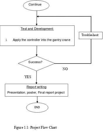
Figure 1.1: Project Flow Chart
Report writing
Presentation, poster, Final report project Test and Development:
i. Apply the controller into the gantry crane
END
Success? Continue
6 Figure 1.1 shows the flow chart of this project. The first step is to understand the project and do researches about gantry crane, DFS controller, vibrate sensor, sway angle sensor and the motor controller. The research is to identify the function of the gantry crane, the specification needed and the parameter that will be used to design the hardware. The DFS controller contain the mathematical method that require the deeply understand of the calculation.
Next step is to run the simulation of the gantry crane system in the MATLAB and try to add the DFS controller. The result of the simulation, with and without the DFS controller is then compared. If the result is not same as the expectation, the simulation is done again by redoing the calculation. After the result is obtained, this project is proceed to the hardware design. In this section, the focus is in the circuit design and construction, built of the gantry crane model and the motor controller circuit.
7 1.6 Thesis Outlines
This thesis consists of six chapters. The following chapters are the outline of the implementation of Delayed Feedback Signal to the gantry crane system.
Chapter I Will discuss briefly the overview of this project such as introduction, objectives, problem statement, scope of the project, methodology and thesis outlines.
Chapter II Contains the research and information about the project on several important concepts of the gantry cranes, the swing control, technology and tools used in the study. Every facts and information, which found through journals or other references, will be compared and the better methods have been chose for the project. This chapter will also include several types of crane.
Chapter III Includes the detail about designing and modeling the gantry crane system.
Chapter IV Includes the detail about simulation results, analysis, observation and discussion of the performance of the Delayed Feedback Signal technique that presented in. This includes the simulation part and the real part.
Chapter V Includes the detail about the hardware design involved schematic diagram, PCB layout, components required and working principle for each circuit. In this chapter also discuss about the components that required completing the gantry crane model, and the sensor circuit used.
CHAPTER II
LITERATURE REVIEW
Literature review in this chapter is to make a research on the several techniques and learn from the past to make the gantry crane project more successful. The whole effort of studying the gantry crane, the mathematical method and the DFS controller will leads to the result as expected.
2.1 Study of Gantry crane
Gantry cranes are designed for lifting and positioning loads. The various types of gantry cranes, including the aluminum gantry crane, the steel gantry crane and the portable gantry crane, are essential for the efficient operation of many industrial facilities, factories, shipyard, and high building constructions. These cranes are similar to overhead cranes except that they have a bridge for carrying the unit's trolley and are usually supported by two or more rigid legs. Additional related equipment that many industrial companies find indispensable include the lifting jib, the hoist trolley, the festoon system, the chain hoist and the portable lift. Study of the control system for the gantry crane is complicated since the different type of crane and it various applications on the industry. Some applications require traversal time, no swing motion of goods when loads moved, and optimization motion of trolley.
9 The crane should move the loads as fast as possible without causing any excessive movement at final position. However the gantry crane, mostly result in a swing motion when payloads suddenly stop after fast motion. The swing motion can be reduce but need the time consuming. Research on the control methods that will eliminate the sway angle of the gantry crane has found the great deal of interest for many years. Active sway angle control of gantry crane indirectly produces sources that absorb the energy caused by unnecessarily sway angle of string consequently to reduce the effect on the crane system.
Research on the control methods that will eliminate the vibration of the system found a great deal of interest for many years. To solve the problem arising due to the unwanted structural vibrations there are 2 methods used which passive and active control. The passive control methods consist of mounting passive material on the structure in order to change dynamic characteristics. The method is expensive and work at high frequencies. The active vibration control relate to generating unnaturally sources that absorb the energy caused by the unwanted vibrations to reduce the effect to the crane system. Leug in 1930 is among the first researcher who used the active vibration control to cancel the noise vibration[1].