i
“I hereby declare that I have read this report and in my opinion this report is sufficient in terms of the scope and quality for award of Bachelor of Engineering
Mechanical With Honours.”
Signature : ..………
Supervisor’s Name: MR. ZAIRULAZHA BIN ZAINAL
ii
GANTRY CRANE WITH ON –OFF MOTOR COMMAND : DESIGN AND IMPLEMENTATION
MOHAMMAD NASIRUDDIN BIN MAHFOZ
This report is submitted in partial fulfillment of requirements for the Bachelor Degree of Mechanical Engineering (Design And Innovation) With Honours
Faculty of Mechanical Engineering Universiti Teknikal Malaysia Melaka
iii
“I hereby declare that this report is the result of my own work except for quotes as cited in the references.”
Signature : ……….
Author : MOHAMMAD NASIRUDDIN BIN MAHFOZ
iv
ACKNOWLEDGEMENT
First and foremost, I would like to thank God for His blessing. He gave me physical and mental strength to carry on my final year project up to completion
I take this opportunity to express my profoundest gratitude and deepest regards to all those who gave me the possibility to successfully complete this PSM. I am deeply indebted to my Project Supervisor, Mr Zairul Azha Bin Zainal. I wishes to express a million thanks for his exemplary guidance, monitoring and constant encouragement through out the development of the project. In those moments of uncertainty and doubts when things used to turn dark without a clear understanding of the knowledge that he tried to share, his kind and patient way of explaining had indeed a soothing effect. The blessing, help and guidance given from time to time shall indeed carry me a long way in the journey of life on which I am about to embark in the near future.
I wish to express my sincere gratitude and appreciation to all my friends for their helpful suggestions in developing this project, for their support and encouragement to me.
v
ABSTRACT
.
vi
CONTENTS
CHAPTER TITLE PAGE
SUPERVISOR VERIFICATION i
PAGE TITLE ii
DECLARATION iii
ACKNOWLEDGEMENT iv
ABSTRACT v
CONTENTS vi
LIST OF TABLES xii
LIST OF FIGURES xiv
LIST OF SYMBOLS xvii
LIST ABBREVIATIONS xviii
LIST OF APPENDIXS xix
I PROJECT INTRODUCTION
1.1 Introduction 1
1.2 Objective 2
1.3 Problem Statement 2
1.4 Scope of Work 3
vii
II LITERATURE REVIEW
2.1 Background of a Gantry Crane 6
2.2 Motion Control System 19
2.2.1 Stepper Motor 19
2.2.1.1 Operation Principle of Stepper Motor 21
2.2.2 DC Motor 22
2.2.3 Comparison between the DC Motor
and Stepper Motor 25
2.3 Serial Port 27
2.3.1 Serial connection 28
2.3.2 Transmitting data 31
2.3.3 Receiving data 32
2.4 Potentiometer 33
2.4.1 Principle of potentiometer 34 2.4.2 Construction of potentiometer 35 2.4.2.1 Linear Taper Potentiometer 35 2.4.2.2 Logarithmic potentiometer 35
2.4.2.3 Rheostat 36
2.5 Application of potentiometer 37
2.5.1 Audio control 37
2.5.2 Television 38
2.5.3 Transducer 38
2.5.4 Computation 38
2.6 Microcontroller 39
viii
III MATHEMATICAL MODELING
3.1 Desired Motion 43
3.2 Modeling of the Gantry Crane 44 3.3 Derivation of the Equations of Motion 45
3.4 Linearization 48
IV RESEARCH METHODOLOGY
4.1 Introduction 49
4.2 Hardware Development 51
4.2.1 Crane design system 51
4.3 Design of Gantry crane 55
4.3.1 Part design 55
4.3.2 Body part 56
4.3.3 Trolley 57
4.3.4 Product assembly 58
4.4 Hardware system development 59
4.5 Prototyping 62
4.5.1 Manufacturing process of main body part 62 4.5.2 Manufacturing process of trolley part 67
4.5.3 Assembly process 68
4.6 Interface circuit 71
4.6.1 Microcontroller 71
4.6.1.1 Microcontroller schematic 73 4.6.2 MAX 232 CPE motor driver Ic 75
4.6.3 Power supply 76
ix
4.7 Software development
4.7.1 Visual basic 81
4.7.2 Visual basic programming 83 4.7.3 Software development for microcontroller 85
4.7.3.1 Flow Chart for Basic Programming
Language 85
4.7.3.2 MP Lab 86
4.7.3.3 Basic language 87 4.7.3.4 PIC programmer 87
V ANALYSIS AND RESULT
5.1 Analysis 91
5.1.1Structural analysis 91
5.1.2Scope of analysis 92
5.1.3 Procedure analysis of link shaft 93
5.2 Result 97
5.2.1 Stress 97
5.2.2 Displacement 98
5.2.3 Strain 99
5.2.4 Discussion For Link Shaft 100 5.3 Analysis of housing bearing 101 5.4 Result
5.4.1 Stress 101
5.4.2 Displacement 103
5.4.3 Strain 104
5.4.4 Discussion For Housing Bearing 105
x
VI CONCLUSION AND RECOMMENDATION
6.1 Conclusion 116
6.2 Recommendation 117
xi
LIST OF TABLES
NO TITLE PAGE
2.1 Comparison between servo motor and stepper motor 25 2.2 Difference types of microcontrollers 40
4.1 Dimension of lab scale crane 52
4.2 Dimension of trolley 54
4.3 Main function of the control panel 84 4.4 The description of debug icon 86
4.5 Micro pro icon 88
5.1 Analysis of link shaft 100
5.2 Analysis of housing bearing 105
5.3 Table of data obtained during experiment for crane position 108 5.4 Table of data obtained during experiment for crane sway angle 111
5.5 Crane’s position over time 113
xii
LIST OF FIGURES
NO TITLE PAGE
1.1 Project flow chart 4
2.1 Crane body frame 7
2.2 Monorail system 8
2.3 DC chain system 9
2.4 DR rope hoist 10
2.5 Air hoist 11
2.6 Electric wire rope hoist 12
2.7 Electric chain hoist 13
2.8 Ex – proof chain block 14
2.9 Fixed height steel gantry crane 15 2.10 Pillar and wall-mounted slewing jib crane 16 2.11 Super – post panama portainer crane 17
2.12 Double grider crane 18
2.13 Dc motor 22
2.14 Force in DC motor 23
2.15 Magnetic field in DC motor 23
2.16 Torque in DC motor 23
2.17 Current flow in DC motor 23
2.18 Pin connector 29
2.19 System of potentiometer 33
xiii
2.21 Micro controller based system 39 2.22 Some of the various PICs from Microchip 41
3.1 Model of gantry crane 44
4.1 Scope of methodology 50
4.2 Main body of lab scale crane 51
4.3 Trolley system of the lab scale crane. 52
4.4 Trolley system 53
4.5 Part in trolley system 53
4.6 Main body part 56
4.7 Trolley part 57
4.8 Part assembly 58
4.9 Lab scale gantry crane system 60 4.10 Basic concept of automatic gantry crane system 61
4.11 Disc saw 63
4.12 Drilling process 64
4.13 Welding process 65
4.14 Sample of part use bending process 65
4.15 Facing step using grinder 66
4.16 Part assembly of trolley part 67
4.17 Main part 68
4.18 Base part 68
4.19 Trolley assembly 69
4.20 Motor controller circuit 69
4.21 Block diagram for PIC 16F72 73
4.22 Microcontroller schematic 74
4.23 Block diagram of 12 V power supply to microcontroller 76 4.24 Block diagram of 5V power supply to the motor drive 77
4.25 Schematic circuit 78
4.26 PCB layout 80
xiv
4.28 Control panel of Automation system using visual basic 83 Programming
4.29 Flow chart for basic programming language 85 4.30 An icon for the debugging is added to the icon bar 86 4.31 The equipment used for program the IC 88
5.1 COSMOSWorks Manager tab 93
5.2 Define the static study 93
5.3 Material selection 94
5.4 apply fix restraint and force 95
5.5 Mesh the assembly 96
5.6 Run the analysis 96
5.7 Von misses stress analysis 97
5.8 Displacement analysis 98
5.9 Strain analysis 99
5.10 Von misses stress analysis 102
5.11 Displacement analysis 103
5.12 Strain analysis 104
5.13 Connect USB port to computer 106
5.14 Initial position of crane box 106
5.15 Crane system control box in Visual Basic 107
5.16 Measure position by using measuring tape 107
5.17 Graph of experimental result for crane position without 109 Controller
5.18 Graph of theoretical result for crane position without controller 109
xv
5.20 Crane System’s Control Box in Visual Basic 110 5.21 Graph of experimental result for crane angle without controller 112
xvi
LIST OF SYMBOLS
M - Trolley mass m - Payload mass
l - Length of the hoisting rope F
x - Input force
G - Gravitational acceleration = 9.81ms-2 G - Centre point
S - Point of suspension x - Trolley position x
- Velocity
x
- Acceleration - Sway angle - Angular velocity
xvii
LIST OF ABBREVIATIONS
A/D - Analog-to-digital CPU - Central Processing Unit D/A - Digital-to-Analog DAQ - Data Acquisition Board DC - Direct Current
EEPROM - Electrically Erasable Programmable Read Only Memory EIA - Electronic Industries Alliance
FFT - Fast Fourier Transform I/O - Input / Output
MCU - Microchip Microcontroller NI - National Instruments
PIC - Peripheral Interface Controller RAM - Random-Access Memory RTW - Real Time Workshop RS - Recommended Standard ROM - Read-only Memory
xviii
LIST OF APPENDIXS
NO TITLE
1
CHAPTER I
PROJECT INTRODUCTION
This chapter will be discussed about the design and implementation of lab scale gantry system with on-off motor commands mechanism. The project introduction, project objective, problem statement, and scopes of work and methodology will also be presented.
1.1 Introduction
Gantry cranes are widely used for transporting heavy loads and hazardous materials in building constructions. The crane should move the load as fast as possible without having any excessive payload motion at the final position. However, most of the common gantry cranes result in a swing motion when payload is suddenly stopped after a fast motion. The swing motion can be reduced however; it is often time consuming processes which eventually affect the productivity (operational efficiency) in building constructions.
2
component and study electronics and mechanical parts related as well as to do mechanical drawing for gantry crane also do in this project. The development of the system is about the arrangement of the lab scale gantry crane system also discuss in this project. So the whole project are to develop the lab scale gantry crane system that can be integrated with the software and make sure to be successful.
1.2 Objective
The objective of this project is to design a gantry crane system with on-off motor commands mechanism that can move as robustness, quickly, accurately and safely as possible without vibration from an initial position to target position and also do interfacing between hardware and software for the prototype.
1.3 Problem Statement
3
1.4 Scopes of Work
While doing the project, the scope of work plays a very important role. There is a guideline which student should attain to fulfill the requirement of project. The scopes of work are listed as below:
i. Study the basic concept and the dynamic behavior of gantry crane system, sensors, DC motors, and other electronic part.
ii. Fix the weight of the load and the length of the string for gantry crane. iii. Design the gantry crane layout by using the CATIA.
iv. Study the response of the system in term of structural analysis using COSMOSWORK.
v. Construct the gantry crane that can be use for automatic control.
4
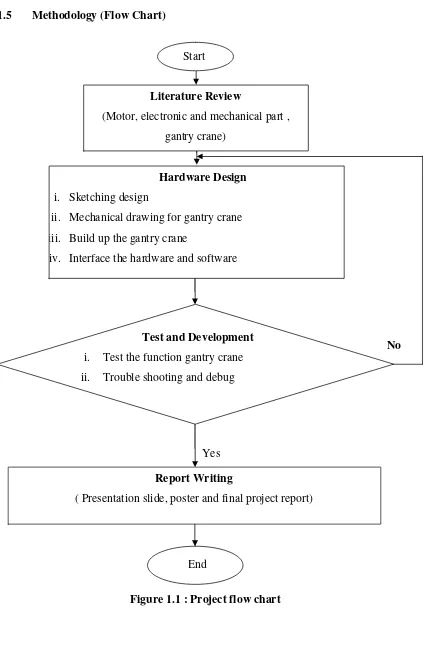
[image:22.595.113.537.97.751.2]1.5 Methodology (Flow Chart)
Figure 1.1 : Project flow chart
No Literature Review
(Motor, electronic and mechanical part , gantry crane)
Hardware Design i. Sketching design
ii. Mechanical drawing for gantry crane iii. Build up the gantry crane
iv. Interface the hardware and software
Report Writing
( Presentation slide, poster and final project report)
End
Test and Development i. Test the function gantry crane ii. Trouble shooting and debug
Start
5
CHAPTER II
LITERATURE REVIEW
6
2.1 Background of a Gantry Crane
Gantry cranes commonly used in numerous industrial applications, such as the loading and unloading of containers, nuclear waste handling facilities, factory automation and basically in any industry which requires heavy goods to be lifted and moved.
The study of the control of the crane is complex, as different industrial applications require different control systems. Some applications require a fact traversal time, and optimization motion of the cart is required. Others require very little or no swing of the goods as they are being moved. Some require that all three dynamics of the crane be optimally controlled likes load positioning swing cancellation and load height.
Gantry cranes are particularly suited to lift heavy objects in shipbuilding where the crane straddles the ship allowing massive objects like ship engines to be lifted and moved over the ship. Two famous gantry cranes built in 1974 and 1969 respectively are Samson and Goliath, which reside in the largest dry clock in the world in Belfast, Northern Ireland [ 1 ]. Each crane has a span of 140 meters and can lift loads of up to 840 tones to a height of 70 meters, making a combined lifting capacity of over 1,600 tones, one of the largest in the world [ 1 ].