DOI: 10.12928/TELKOMNIKA.v11i3.1157 441
Analysis Characteristics of On/Off Grid Tie Inverter and
Implementation in Microgrid
Rudy Setiabudy*1, Hartono BS2, Budiyanto3
Faculty of Engineering, University of Indonesia, Depok 16424
*Corresponding author, e-mail: [email protected], [email protected], [email protected]
Abstrak
Salah satu karakteristik Jaringan Listrik Mikro (JLM) adalah dimungkinkan untuk dapat diintegrasikan dengan jaringan listrik publik (PLN/grid) atau bekerja secara mandiri terlepas dari jaringan publik. Selain itu pada JLM juga dimungkinkan untuk mensuplai kelebihan listrik kejaringan dan tetap mampu menyalurkan daya ke beban lokal meskipun terputus dari jaringan. Tidak semua perangkat inverter dapat digunakan pada jaringan listrik mikro, berkaitan dengan beberapa kriteria yang harus dipenuhi tersebut. Bagaimana karakteristik dari on-off grid tie inverter (on-off GTI) serta bagaimana membangun JLM menggunakan on-off GTI menjadi topik kegiatan penelitian ini. Berdasarkan hasil pengujian on-off GTI dapat digunakan pada jaringan listrik mikro, dengan kemampuan mensuplai daya ke jaringan pada saat kelebihan daya ataupun disuplai jaringan pada saat kekurangan daya. Inverter on-off GTI mampu bekerja mandiri ketika tidak ada daya dari jaringan.
Kata kunci: Microgrid, On-off grid tie inverter, MPPT, Solar cell
Abstract
One characteristic of microgrid is possible to be integrated with the public electricity network (PLN/grid) or work independently of the public network. Additionally on microgrid is also possible to supply excess power to the grid and still be able to supply power to local load even when disconnected from grid. Not all inverter devices can be used on a microgrid, associated with some of the criteria that must be met. How do the characteristics of on-off grid tie inverter (GTI on-off) and how to build microgrid using on-off GTI became topic of this research activity. Based on results of testing, on-off GTI can be used on microgrid, with ability to supply power to network when excess power or supplied from network at the time of power shortage. As well as on-off GTI is able to work independently when there is no power from network.
Keywords: Microgrid, On-off grid tie inverter, MPPT, Solar cell
1. Introduction
The use of renewable energy sources (RES) as a solution to solve problem of increasing demand for electricity, more widely used. This is due to several reasons, in addition to depletion of energy reserves that's derived from fossil fuels, the use of renewable energy sources can also reduce impact of environmental pollution generated by fossil fuels. Besides that RES is also widely used as a solution to the problem of electricity in remote areas. The high costs for transmission and distribution of electric power to customers is also a reason to consider use of RES as an alternative solution to meet demand of electric power [1].
The development of distributed generation (DG) is to unite all distributed power into microgrid. In microgrid, in addition consists of several distributed power, called micro source, there are also several energy storage and certain types of connected load and it all controlled either centrally or decentralized at each generation [4]. From point of view of operation, each micro source, equipped with power electronics interface circuit and control circuit to meet flexibility factor, power quality and amount of energy output [5]. Power electronics circuits that are used in form of an inverter circuit which can change DC to AC power source. There are several types of inverters ranging from standalone inverters that can not be connected to a grid, grid tie inverter/GTI, inverter that can connect to grid and on-off GTI, the inverter that can work independently or can be connected to grid. One characteristic of microgrid is possible to be integrated with public electricity network (PLN/grid) or work independently disconnect from grid. Additionally on microgrid also possible to supply excess power to grid and still able to supplying power, even when disconnected from grid. Not all inverter devices can be used on a microgrid , associated with some of criteria that must be met. How do the characteristics of on-off GTI inverter as well as how to build a microgrid using on/off GTI inverter to be topic of this research project.
2. Research Method
2.1. Inverter Topology and MPPT a. On-off grid tie inverter (GTI)
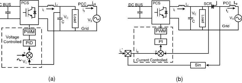
Inverter topology under off grid and on grid according to [6], can be seen in Figure 1. Seen when off grid conditions, reference of the PWM is based on input signal, that generated sine wave form and compared with output voltage conditions. At this condition on-off GTI works as a voltage source. The amount of power generated from sources not everything routed to the inverter output, the amount of power generated is proportional to the required power load.
(a) (b)
Figure 1. Topology of on grid and off grid inverter, (a) topology off - on grid Inverter, (b) topology on-off grid inverter
While at on grid conditions, reference of PWM refers to grid/network voltage. Inverter works as a current source, using MPPT mechanism, power that comes from the source utilized optimally. Where most of power supplied to the load and rest distributed to grid. Connection mechanism from off grid condition to on grid conditions and vice versa, based on several parameters as reference. At time transition from off grid conditions to on grid conditions, it's a necessary parameter settings on voltage, frequency, phase and grid currents references. While for transition from on grid to off grid conditions are affected by errors parameters on grid and setting of voltage references and current grid [7].
b. MPPT (Maximum Power Point Tracking)
observe (P & O) and incremental conductance (INC). MPPT method using P & O algorithm is widely used because it is easier implementation. However, this algorithm has drawbacks such as oscillations in steady conditions around the MPP point and a slow response in event of changes in solar radiation. This algorithm based on criteria, if the operating voltage of PV array disturbed, and if increased power obtained in a particular direction, this means that operating point has moved towards MPP and, therefore, operating voltage must be changed in the same direction [8].
There are three techniques that can be used to resolve P & O algorithm, reference voltage perturbation, reference current perturbation and direct duty ratio perturbation [9]. Meanwhile in INC method, the operating voltage at the terminals of PV array is always adjusted to the MPP voltage based on the addition of an additional conductance voltage on the PV array [10]. This method based on calculation of power gradient toward voltage at MPP point is 0, and the gradient will be worth positive if it on the left of MPP, and is worth negative if on the right of MPP [11].
Besides two methods above, there are several methods that can be used to obtain operating MPPT point of PV array among others, Parasitic Capacitance, Voltage Based Peak Power Tracking, and Current Based peak power Tracking [12].
2.2. Testing Methods
2.2.1.Testing On/off GTI on off grid and on grid condition
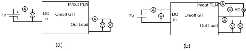
On/off GTI is the inverter that can operate independently (islanding) or can be connected to grid. On/off GTI has output connections to local load and connections to interconnect with grid. This test is intended to determine the characteristics of on/off GTI in delivering power to load both locally and to grid. Testing is done by connecting directly input of inverter to circuit of solar cells. Tests using energy source from 4x180Wp and 3x180Wp PV.
(a) (b)
Figure 2. On-off GTI circuit with PV input (a) off grid (b) on grid
In testing on off grid conditions, measured in solar radiation, voltage and output current of PV , and output of inverter such as current, voltage and power to local load (load out). In this configuration, not all radiation power is converted to electricity supplied everything to load, but according to amount of need to load to maintain value of voltage and frequency that must be met. From these measurements it can be seen the average power dissipation required by the inverter is given by Equation 1.
(1)
Where is :
Ppv : output power of solar panel (PV)
PL : Load power
Pdi : Dissipation power of inverter
Measurement of current, voltage and power performed on output of inverter. From measurement results can be calculated amount of electrical power is converted to AC magnitude is given by Equation 2.
(2)
Sign of in expressed direction of power flow, positive sign when inverter is supplying power to grid, and negative when inverter is supplied power from grid.
efficiency of Inverter is given by Equation 3.
%
(3)2.2.2. Testing of parallel On/off GTI connected to network (on grid)
In this testing will be measured characteristics of inverter when two inverters connected in parallel and connected to network, simulating the conditions of microgrid. One of activities that need to be observed is the mechanism for the power of each inverter and power of the network.
Figure 3. Testing circuit of parallel 2 On/off GTI and grid connected
Power flow equations in this circuit is given by Equation 3 and 4.
(4)
(5)
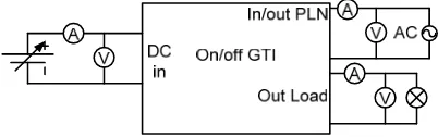
2.2.3. Testing the quality of power On/off GTI
In this testing will be tested imposition On/off GTI, to provide input voltage DC and AC loads are variable. In this activity was also measured quality of power generated by on/off GTI both conditions on grid or off grid. One of the advantages JLM is a better power quality as well more reliable.
3. Results and Discussion
Measurement results and discussion will be reviewed in any activity testing. Testing begins by measuring on/off GTI on off grid condition.
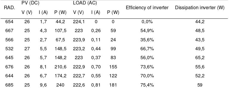
Testing characteristics On/off GTI when not connected to network/off grid conditions was performed using PV energy source for 4x180Wp and 3x180Wp. Measurement results show when conditions off grid, On/off GTI works well in supplying power to load. At no load generated power is used only for operation of inverter, a power dissipation of inverter which is average for PV source for 4x180Wp is 50.23 W. While PV source 3x180Wp average amount of inverter power dissipation of 52.21 W. In this event connection to battery is not connected, simply connected to local load then amount of power produced relatively similar for both configurations, although at different radiation conditions, as shown in data table 1 and table 2.
Table 1. Power flow of on/off GTI unconnected to grid with 4x180Wp PV
RAD.
PV (DC) LOAD (AC)
Efficiency of inverter Dissipation inverter (W) V (V) I (A) P (W) V (V) I (A) P (W)
Table 2. Power flow of on/off GTI unconnected to grid with 3x180Wp PV
RAD. PV (DC) LOAD (AC) Efficiency of inverter Dissipation inverter (W) V (V) I (A) P (W) V (V) I (A) P (W)
Table 3. Power flow of on/off GTI connected to grid with 4x180Wp PV
Table 4. Power flow of on/off GTI connected to grid with 3x180Wp PV
RAD.
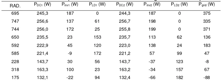
Table 5. Power flow of parallel 2 on/off GTI connected to grid with 4x180Wp PV
RAD. PDC1 (W) Pinv1 (W) PLD1 (W) PDC2 (W) Pinv2 (W) PLD2 (W) Pgrid (W)
(a) (b) (c)
(d) (e)
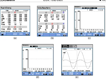
Figure 5. Measurement results of power quality On/off GTI in off grid condition, (a) rated power, (b) rated voltage, (c) current harmonics, (d) voltage harmonics, and (e) form of output voltage
(a) (b) (c)
(d) (e) (f)
Figure 6. Measurement results of power quality On/off GTI in on grid condition.
To test power quality of on/off GTI, the first test done to see characterization of on/off GTI when off grid conditions. In off grid conditions on/off GTI only local supply power to load is not to grid. In these tests measurements for 2-level load with results that are not so much different especially on power quality, so that here shown one measurement results only. Seen from measurement results, especially power quality, on/off the GTI have form of pure sine wave output with are not too many harmonic of currents and voltages.
(a) (b)
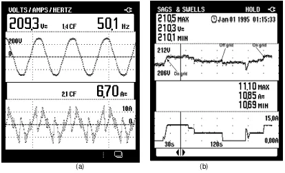
Figure 7 (a). Conditions of inverter output voltage and current on grid connected with PLN. (b). changes in value of voltage and current flows on grid connected
On test of connected to grid, where on/off GTI connected to a grid, measuring at local load output terminals (out load) and grid connected terminal (In/out PLN). In these tests measurements for 2-level load with results that are not so much different especially on quality of power, so that here only shown one measurement results. The measurement results show inverter output waveform follows voltage network (grid), it is not a pure sine. With the current THD values in particular, for higher network load than local output, this can be understood as network load more varied than local load. However, it also shows harmonics on network do not affect power quality of local load.
(a.)
(b.)
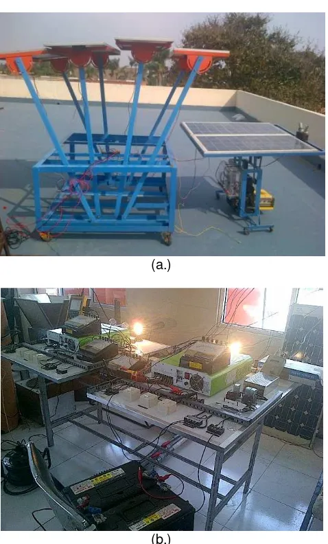
Figure 8. (a.) Solar panel circuit (b.) On-off GTI circuit
4. Conclusion
Based on results of tests performed, characteristics required for inverter to operate at microgrid found on On/off GTI. The ability to connect to network and to transfer power both supplying power to network when there is an excess of power or otherwise receiving power from network at the time of power shortages to distributed to load. Based on measurements of the average magnitude of the power dissipation of inverter on/off GTI of 51.22 W and the efficiency of the inverter is increasing in line with increase amount of power distributed, until 78.8%.
Based on power quality measurements seen quality of power generated on-off GTI is relatively good with the factor cos =0,99 when disconnected from the network (off grid) and cos =1 when connected to the network (on the grid) and THD=6 , 2% at off grid and THD=4.6% at the moment on the grid. Based on the test results it can be said device on-off GTI used can be used on microgrid.
References
[1] Jeremi Martin. Distributed vs. centralized electricity generation: are we witnessing a change of paradigm? An introduction to distributed generation. Energy Track at HEC Paris, may 2009.
[2] G Pepermans, J Driesen, D Haeseldonckx, R Belmans, W D’haeseleer. Distributed generation: definition, benefits and issues. Energy Policy Elsevier. 2005; 18: 787–798.
[4] Lasseter R, Robert H. MicroGrids. Power Engineering Society Winter Meeting IEEE. 2002; 1: 305-308.
[5] S Chowdhury, SP Chowdhury, P Crossley. Microgrids and Active Distribution Networks. IET Renewable Energy Series 6. The Institution of Engineering and Technology, 2009.
[6] Guoqiao Shen, Dehong Xu, dan Danji Xi. Novel Seamless Transfer Strategies for Fuel cell Inverters from Grid-tied Mode to Off-grid Mode. Applied Power Electronics Conference and Exposition, 2005; 1: 109-113.
[7] Zhilei Yao, Lan Xiao, dan Yangguang Yan. Seamless Transfer of Single-Phase Grid-Interactive Inverters between Grid-Connected and Stand-Alone Modes. IEEE Transactions on Power Electronics. 2010; 25(6): 1597-1603.
[8] Nicola Femia, Giovanni Petrone, Giovanni Spagnuolo, Massimo Vitelli. Optimization of Perturb and Observe Maximum Power Point Tracking Method. IEEE Transactions on Power Electronics. 2005; 20(4): 963 – 973.
[9] MA Elgendy, B Zahawi, DJ Atkinson. Assessment of Perturb and Observe MPPT Algorithm Implementation Techniques for PV Pumping Applications. IEEE Transactions on Sustainable Energy. 2012; 3(1):21-33.
[10] M Lokanadham dan, K Vijaya Bhaskar. Incremental Conductance Based Maximum Power Point Tracking (MPPT) for Photovoltaic System. International Journal of Engineering Research and Applications (IJERA), ISSN: 2248-9622. 2012; 2(2): 1420-1424.
[11] S Gomathy, S Saravanan, S Thangavel. Design and Implementation of Maximum Power Point Tracking (MPPT) Algorithm for a Standalone PV System. International Journal of Scientific & Engineering Research. 2012; 3(3): 1-7.
[12] Nazih Moubayed, Ali El-Ali, Rachid Outbib. A comparison of two MPPT techniques for PV system.