SMART COLOR SORTING ROBOT
SITI NADRAH BINTI SELAMAT
SMART COLOR SORTING ROBOT
SITI NADRAH BINTI SELAMAT
This report is submitted in partial fulfillment of the requirements for the award of the Bachelor of Electronic Engineering(Electronic Telecommunication) With Honours
Faculty of Electronic and Computer Engineering Universiti Teknikal Malaysia Melaka
UNIVERSTI TEKNIKAL MALAYSIA MELAKA
FAKULTI KEJURUTERAAN ELEKTRONIK DAN KEJURUTERAAN KOMPUTER
BORANG PENGESAHAN STATUS LAPORAN PROJEK SARJANA MUDA II
Tajuk Projek : ………
Sesi
Pengajian :
Saya ………..
(HURUF BESAR)
mengaku membenarkan Laporan Projek Sarjana Muda ini disimpan di Perpustakaan dengan syarat-syarat kegunaan seperti berikut:
1. Laporan adalah hakmilik Universiti Teknikal Malaysia Melaka.
2. Perpustakaan dibenarkan membuat salinan untuk tujuan pengajian sahaja.
3. Perpustakaan dibenarkan membuat salinan laporan ini sebagai bahan pertukaran antara institusi
pengajian tinggi.
4. Sila tandakan ( √ ) :
SULIT*
*(Mengandungi maklumat yang berdarjah keselamatan atau kepentingan Malaysia seperti yang termaktub di dalam AKTA RAHSIA RASMI 1972)
TERHAD** **(Mengandungi maklumat terhad yang telah ditentukan oleh
organisasi/badan di mana penyelidikan dijalankan)
TIDAK TERHAD
Disahkan oleh:
__________________________ ___________________________________
(TANDATANGAN PENULIS) (COP DAN TANDATANGAN PENYELIA)
“I hereby declare that this report is the result of my own except for quotes as cited in the
references”
Signature :
Author : Siti Nadrah Binti Selamat
“I hereby declare that I have read this report and in my opinionthis report is sufficient in terms of the scope and quality for the award of Bachelor of Electronic Engineering
(Telecommunication Electronics) With Honours.”
Signature :
Supervisor‟s Name : Madam Nurmala Irdawaty Bt Hassan
ACKNOWLEDGEMENT
All praise be too might ALLAH S.W.T Merciful and Beneficent for the strength and blessing throughout the entire research and completion of this PSM.
First and foremost, all praise is due to Allah, Lord of the worlds for giving us wellness, intellect and strength to do this project and also the following individuals. Without them, it would not be possible for us to complete this project. In particular, I owe a debt of gratitude to our project supervisor Miss Nurmala Irdawaty bt Hassan for guide, and giving advice and idea to us complete our project. Without her, this project cannot be done.
Next, I would like to say a million thanks to my parents for their support and understanding in allowing me to focus my attention to this project. They have always been the driving force in pushing us to excel in everything that I do. To our friends, all of you have been an inspiration to the both of us.
Finally, I would also like to extend our utmost gratitude to all the lecturers of University Technical Malaysia Malacca (UTeM) for their guidance and patience. Their teachings have thought me that education and knowledge are vital in life if we wish to succeed.
ABSTRACT
ABSTRAK
„Smart Color Sorting Robot‟ adalah sistem yang membolehkan sesebuah robot
TABLE OF CONTENTS
CHAPTER TITLE PAGE
TITLE OF PROJECT
STATUS CONFIRMATION FORM DECLARATION
ACKNOWLEDGEMENT ABSTRACT
ABSTRAK
TABLE OF CONTENTS LIST OF TABLES LIST OF FIGURES
LIST OF ABBREVIATION LIST OF APPENDICES
i ii iii v vi vii viii xi xii xiv xv
I INTRODUCTION 1.1 Project Background 1.2Objectives
1.3Scope Work 1.4Problem Statemant 1.5Significant of Project 1.6Report Structure
1 1 2 3 3 4 5
II LITERATURE REVIEW
2.1 Application Review
2.1.1 Line Follower 2.1.2 Color Sensor
2.1.2.1 Similarity Matching vs. Thresholding
2.1.2.2 Positioning of Photoresistor 2.2 Controller Review
2.2.1 Microcontroller (PIC16F876A) 2.3Sensor Review
2.3.1 Infra Red Sensor
2.3.1 Photoresistor (LDR) 2.4 Driver Review
2.4.1 L293D
2.5 Component Review 2.5.1 Servo Motor
2.5.2 Gearbox with DC Motor 2.6 Power Supply
2.7 Electrical Part 2.7.1 DC Motor
6 7 7 8 9 9 11 11 12 12 12 13 14 14 15 16 16
III METHODOLOGY
3.1 Project Methodology
3.2 Explanation of Project Planning 3.2.1 Searching For Project Title
3.2.2 Understanding The Circuit Operation And Circuit analysis
3.2.3 Preparing For Proposal 3.2.4 Searching For Components 3.2.5 Testing The Circuit Function 3.3 Flow Process of Project
3.3.1 Main Flowchart
3.3.1.1 Main Controller 3.3.1.2 Sensor Circuit 3.3.1.3 Driver Motor 3.3.2 Hardware Flowchart 3.3.3 Software Flowchart
3.4 Printed Circuit Board (PCB) Manufacturing 3.4.1 PCB
3.4.2 Classification of PCB‟s 3.4.3 Types Of The PCB‟s 3.5 PCB Design
3.5.1 Schematic Design 3.5.2 Schematic
3.5.3 Layout Design
3.5.4 The Printed Circuit Board Layout (PCB) 3.5.4.1 Method To Make The Layout 3.5.5 PCB Fabrication
3.5.6 Component Placement And Orientation 3.5.7 Etching Process
3.6 Prepare The PCB For Use And Drill The PCB 3.7 Drilling
3.8 Drilling process 3.9 Soldering Process 3.9.1 Solder onto a PCB
3.10 Testing and Troubleshooting The Circuit Function
3.11 Designing a Body Structure 3.11.1 Base Body Development 3.11.2 Tower Ball Development 3.11.3 Ejector Development
IV
V
RESULT AND DISCUSSION
4.1 Result
4.2 Data Analysis and Discussion
4.3 Similarity Matching and Thresholding
CONCLUSIONS AND RECOMMENDATIONS
5.1 Conclusions 5.2 Recommendations
REFERENCE
APPENDICES
45
45 48 51
52
52 53
54
TABLES OF TABLES
NO TITLE Page
Table 3.3.1.1 Table of I/O List 24
Table 3.3.1.2 The Operation of The Motor 2 Driver 27 Table 4.2.1
Table 4.2.2
Voltage Reading Decimal Reading
LIST OF FIGURES
NO TITLE PAGE
Figure 1.1 Overview of The project Sequence 2
Figure 2.1.1 (a) Simple Closed Loop System 6
Figure 2.1.1 (b) Block Diagram of Line Follower 6
Figure 2.1.2.2 Positioning of Photoresistor 8
Figure 2.2.1 PIC16F876A Pin Diagram 9
Figure 2.3.1 Infra Red Sensor 11
Figure 2.3.2 LDR 12
Figure 2.4.1 (a) L293D 13
Figure 2.4.1 (b) L293D Pin Diagram 13
Figure 2.5.1 Servo Motor 14
Figure 2.5.2 Double Gearbox with DC Motor 15
Figure 2.7 Motor Control Circuit 17
Figure 3.3.1 Flow of Main Process in This Project 22
Figure 3.3.1.1(a) Sequence to assemble These Circuit 23 Figure 3.3.1.1(b) Controller circuit Schematic Diagram 24
Figure 3.3.1.2(b) Voltage Decreases with Light 25
Figure 3.3.1.2(c) Schematic Diagram for LDR 26
Figure 3.3.1.3 Schematic Diagram for L239D 27
Figure 3.3.2 Process in Developing Hardware Part 28
Figure 3.3.3 Figure 3.5.7(a) Figure 3.5.7(b) Figure 3.5.7(c) Figure 3.5.7(d) Figure 3.5.7(e) Figure 3.6 Figure 3.8 Figure 3.9.1
Process in Developing Software Part Circuit on Plastic Transparent Circuit Printed Put onto PCB Board Exposure Units
PCB After Developing
PCB Circuit After Come Out from MEGA Drilled PCB Drilling Process Soldered PCB 29 36 36 37 37 38 39 40 42
Figure 3.11.1 Base Body with Controller Circuit 43
Figure 3.11.2 Figure 3.11.3 Tower Ball Ejector 43 44
Figure 4.1(a) Main Line Sensor 46
Figure 4.1(b) Station Sensor 46
Figure 4.1(c) Robot at Station 1 46
Figure 4.1(d) Press „Run‟ Button to Move 46
Figure 4.1(e) Orange Ball (Station 2) 47
Figure 4.1(f) Red Ball (Station 3) 47
LIST OF APPENDICES
NO TITLE PAGE
A B C D E F G
L293D Datasheet PIC16F876A Datasheet
Body Structure‟s Design
PCB Layout Design Technical Drawing Source Code Project Planning
CHAPTER I
INTRODUCTION
This chapter will briefly discuss on the project overview. The objective, scope, and thesis outline will be presented in this chapter.
1.1 Project Background
Smart Color Sorting Robot is based on the placing system with some capability to decide the object according to their color. The object will be defined by determining color of the ball while the system will figure which location the object should be located. With the PIC as a controller for the system, a manually feed object which is a coloring ball will be determined by the robot to take and eject them to their exact location or station.
In this project a line follower will brought the ball that will be sense by LDR sensor to right station. A main part in this project is an LDR sensor. Commonly this type of sensor used to detect light. Other applications are for color sensor, line detector, and switching element. Capability of this system to detect the type of this object and it will be chosen based on their color.
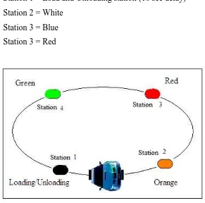
There are four stations in the Color Sorter system that we made. Each station had their own range of color except for the first station which is the load and unloading station.
The ball will be inserting manually by the user. Then the LDR sensor will detect what color is the object, after the detection been done, the decision will be made and the line follower will take the object to the station that been recognized for it.
In this system, there are 4 station;
Station 1 = Load and Unloading station (10 sec delay) Station 2 = White
Station 3 = Blue Station 3 = Red
Figure 1.1 Overview of the Project Sequence
1.2 OBJECTIVES
This project is developed with the purposed to optimizing the productivity, minimizing the cost of the project and make no human mistakes. The main thing of this
project is to study how to communicate the programming language with the color sensor. After that, the line follower system will make its own decision to the station that been programmed. The objective can be summarized as below:
i. To sort the object according to their color. ii. To sort the object to the station accordingly.
iii. To make the system run continuously with less rest.
iv. To make an interface between the programming of line follower and the sensors.
1.3 SCOPE OF PROJECT
This project is subjected to several scope and limitations that are narrowed down to the study.There are a few scopes and guidelines listed to unsure the project is conducted within its intended boundary. This is to ensure the project is heading in the right direction to achieve its intended objectives. The objectives are:
i. Research study on the Programmable Intelligence Computer, PIC16F876A microcontroller and the control system of the circuit.
ii. To acquire the each sensor that use in this project. iii. To design circuitry for the overall system
iv. To develop the program that can integrate and control the overall system. v. To construct the model and test either the robot is function or not.
1.4 PROBLEM STATEMENT
The problems which often occurred in the industrial that can be solve by this project are:
i. By using this project the company can optimize the productivity.
ii. Each company, have their own cost; this project can be minimizing the cost of the company by minimizing the workers.
iii. Usually, the worker maybe doing some mistakes while doing their job, by developing this project, the company can decrease the human mistakes.
1.5 SIGNIFICATION OF THE PROJECT
i. Manage to gain more idea and information about the sensor and valve. ii. Manage to work on the PIC programming
iii. Manage to apply knowledge about the robotic. iv. Manage to build up the robot.
1.6 REPORT STRUCTURE
Chapter one briefly introduces he overall of the project title Smart Color Sorting Robot. The introduction consists of overview, objective, problem statement, scope of work, methodology and structure report.
Meanwhile chapter two discuss about the background of study related to security system. Literature review will produce overall structure of the Smart Color Sorting Robot which shows the relationship between project research and theoretical concept.
Chapter three will explain about the project methodology. Project methodology give details about the method used to solve the problem to complete the project. The method used such as collecting data method, process and analysis data method, modelling and etc.
Chapter four consists of result and discussion of the project, finding and analysis throughout the research and project development.
Lastly, chapter five is the project conclusion. This chapter rounds up the attained achievement of the whole project and reserves suggestions for possible future researches.
CHAPTER II
LITERATURE REVIEW
This chapter is to discuss some fundamental ideas of line follower and color sensor. The features of this project are also including. All components using for this project will be explain as well.
2.1 Application Review
In this project, there is two application will be combine. This application is: 1. Line Follower.
2. Color Sensor.
Thus, the research on this application was revealed and a few references found in order to complete this project.
2.1.1 Line Follower
According to Priyank Patil [1], line follower is a mobile robot that can follow a path. It can follow path whether the path is straight, corner or at whatever direction. A
line follower will sense a line and maneuvering the line follower to stay right on the line
by using infra red sensor as its „nose‟.
If the line follower tries to move out of track, the infrared sensor will give a signal to the brain of the robot to stay on line. This situation is made based on the simple closed loop feedback.
Figure 2.1.1(a): Simple Closed Loop System [1]
R(s) represented as a power supply from 5V and C(s) represented as a direction of the line follower. A suitable program is needed in order to make this line follower
able to track a line and it‟s supposed to think like a „human‟. The overview of this line
follower is shown as Figure 2.1.1(b).
Figure 2.1.1(b): Block Diagram of Line Follower [1]
2.1.2 Color Sensor
According to Society of Robot‟s Article [2], photoresistor cannot see the color of
an object. It only can read the value gain from reflection of the object. The value gain from a various object is difference. Therefore, some research has been made and the result seems to be that photoresistor can be use as color detection element. There are two
methods in order to differentiate object‟s color.
1. Similarity Matching Method 2. Thresholding Method
2.1.2.1 Similarity Matching vs. Thresholding
In reality the sensor must be calibrate before the sensors before work. This means the sensor must sense the object, record the readings, and then make a chart using this data. That way when the robot is doing its thing and senses the same object, it can compare the similarity of the new reading vs. the calibrating reading.
For example, suppose the robot needs to follow a white line on a grey floor. The robot would use a microcontroller to sense the analog value from the sensor. During the calibration phase the robot measured an analog value of 95 for the grey floor, 112 for the white line, and then stored these values in memory. Now your robot is on the line, and a sensor reads 108.
Using the shareholding method, add both calibrated numbers and divide by two to find the average middle number. For example, (95+112)/2 = threshold. Anything above that threshold would be the white line, and anything under would be the grey floor. Similarity matching was used to threshold, if there is three or four colors. This process is to determine how similar each color of the object is to the calibrated value.
![Figure 2.1.1(a): Simple Closed Loop System [1]](https://thumb-ap.123doks.com/thumbv2/123dok/619473.74560/23.612.152.560.498.625/figure-a-simple-closed-loop-system.webp)
